Febco 860 Series Maintenance Manual
Reduced pressure zone assemblies
Hide thumbs
Also See for 860 Series:
- Installation operation & maintenance (4 pages) ,
- Installation instructions (4 pages)
Table of Contents
Advertisement
I N S T A L L A T I O N , O P E R A T I O N , M A I N T E N A N C E
WARNING
!
Read this Manual BEFORE using this equipment.
Failure to read and follow all safety and use information
can result in death, serious personal injury, property
damage, or damage to the equipment.
Keep this Manual for future reference.
NOTICE
If the unit is installed where a protective device is recommended may be
a problem, the assembly should be protected and secured . On
2" (15 - 50mm) units the handles of shutoff valves can be removed to
discourage tampering . A protective enclosure can be installed over the unit
to discourage vandals . If an enclosure is used, it should be installed so that
adequate clearance is available for maintenance and testing . Consult local
codes before installing any type of protective enclosure .
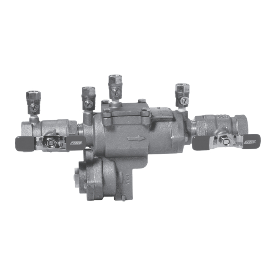
Series 860 Reduced Pressure Zone Assemblies
/
" through
1
2
Read and understand this manual prior to installing,
operating or servicing this equipment.
Maintenance Manual
Models 860, LF860, 860U & LF860U
Table of Contents
Feature and Operating Procedures . . . . . . . . . . . . . . . . . . . . . . . . . . . . . . . . 2
Vandalism . . . . . . . . . . . . . . . . . . . . . . . . . . . . . . . . . . . . . . . . . . . . . . . . . . . . 2
General Service Procedures . . . . . . . . . . . . . . . . . . . . . . . . . . . . . . . . . . . . . 3
Cut-A-Way Drawing . . . . . . . . . . . . . . . . . . . . . . . . . . . . . . . . . . . . . . . . . . . . 3
Troubleshooting Guide . . . . . . . . . . . . . . . . . . . . . . . . . . . . . . . . . . . . . . . . . 4
Check Module Disassembly . . . . . . . . . . . . . . . . . . . . . . . . . . . . . . . . . . . . . 6
Check Module Seal Replacement . . . . . . . . . . . . . . . . . . . . . . . . . . . . . . . . . 6
Check Module Re-Assembly . . . . . . . . . . . . . . . . . . . . . . . . . . . . . . . . . . . . . 7
Relief Valve Repair . . . . . . . . . . . . . . . . . . . . . . . . . . . . . . . . . . . . . . . . . . . . . 7
Testing . . . . . . . . . . . . . . . . . . . . . . . . . . . . . . . . . . . . . . . . . . . . . . . . . . . . . . 9
Air Gap Drain Installation Instructions . . . . . . . . . . . . . . . . . . . . . . . . . . . . . . 9
Exploded View . . . . . . . . . . . . . . . . . . . . . . . . . . . . . . . . . . . . . . . . . . . . . . . 10
Parts List . . . . . . . . . . . . . . . . . . . . . . . . . . . . . . . . . . . . . . . . . . . . . . . . . . . 10
Repair Kits . . . . . . . . . . . . . . . . . . . . . . . . . . . . . . . . . . . . . . . . . . . . . . . . . . 11
Freeze Protection . . . . . . . . . . . . . . . . . . . . . . . . . . . . . . . . . . . . . . . . . . . . . 11
Warranty . . . . . . . . . . . . . . . . . . . . . . . . . . . . . . . . . . . . . . . . . . . . . . . . . . . . 12
IOM-F -860_860U
/
"- 2" (15 - 50mm)
1
2
Series 860
/
" - 2") . . . . . . . . . . . . . . . . . . . . . . . . . . . 11
1
2
Advertisement
Table of Contents

Related Manuals for Febco 860 Series


Summary of Contents for Febco 860 Series
-
Page 1: Table Of Contents
IOM-F -860_860U I N S T A L L A T I O N , O P E R A T I O N , M A I N T E N A N C E Maintenance Manual Series 860 Reduced Pressure Zone Assemblies Models 860, LF860, 860U &... -
Page 2: Feature And Operating Procedures
WITH PROPER INSTALLATION AND MAINTENANCE INSTRUCTIONS COULD RESULT IN PRODUCT FAILURE WHICH CAN CAUSE PROPERTY DAMAGE, PERSONAL INJURY AND/OR DEATH. FEBCO is not responsible for dam- ages resulting from improper installation and/or maintenance . Local building or plumbing codes may require modifications to the information provided . -
Page 3: General Service Procedures
. • 1 crescent wrench 5 . Use caution to avoid damaging any guiding surfaces while handling • 1 medium standard screw driver parts . Do not force parts together . The O-ring seals used in FEBCO • Differential pressure test kit assemblies require only a small tightening force to ensure • 1 medium Phillips screw driver a positive seal . -
Page 4: Troubleshooting Guide
MAINTENANCE MANUAL: MODELS 860, LF860, 860U & LF860U "- 2" (15 – 50mm) Troubleshooting Guide With Differential Pressure Gauge SyMpTOM #1 ReadIng pRObleM: Check Differential Across 2 to 3 psid Leak in #1 or #2 check valve #1 Check Valve 6 to 8 psid and steady Malfunctioning pressure relief valve 2 to 7 psid and steady... - Page 5 MAINTENANCE MANUAL: MODELS 860, LF860, 860U & LF860U "- 2" (15 – 50mm) Troubleshooting Guide (Continued) SyMpTOM #3 CauSe: SOluTIOn: Continuous discharge from relief valve during A. Seat disc dislodged from cavity in Reposition disc in main stem cavity FLOW and NO FLOW conditions the main stem.
-
Page 6: Check Module Disassembly
. To service the checks, you may replace the check modules with opening #2, #3, and #4 test cocks . Allow the test cocks to remain new ones by using check module assembly kits available from FEBCO . open until the reassembling is completed . Test cock #1 should remain Or, you may also replace the rubber components in the check modules closed . -
Page 7: Check Module Re-Assembly
MAINTENANCE MANUAL: MODELS 860, LF860, 860U & LF860U "- 2" (15 – 50mm) Check Module Re-Assembly Relief Valve Repair Use reverse procedure for assembly with the following NOTICE special instructions . Discharge from the relief valve assembly may not indicate a relief valve 1 . - Page 8 MAINTENANCE MANUAL: MODELS 860, LF860, 860U & LF860U "- 2" (15 – 50mm) Relief Valve Repair - continued 7 . Replace O-ring (Item 20) in relief valve cover . Make sure the round bead on the large diaphragm is properly seated in the counterbore of 5 .
-
Page 9: Testing
MAINTENANCE MANUAL: MODELS 860, LF860, 860U & LF860U "- 2" (15 – 50mm) Testing Air Gap Drain Installation Instructions All mechanical devices should be inspected on a regular basis to ensure 1 . Before installation check local codes . This type of drain may not be they are working correctly . -
Page 10: Exploded View
MAINTENANCE MANUAL: MODELS 860, LF860, 860U & LF860U "- 2" (15 – 50mm) Exploded View ITeM deSCRIpTIOn quanTITy Body Tailpiece O-Ring Cover O-Ring Seat O-Ring Inlet Ring " & 1 ") Poppet Seat Disc Disc Retainer Round HD Screw Spring (1st Check Spring) Spring (2nd Check Spring) -
Page 11: Repair Kits
3 . Provide full model number located on I .D . plate . 4 . Give kit number . 5 . A serial number (located on the I .D . plate) will assist in ordering the proper kits . 6 . Contact your local FEBCO Parts Distributor . ORdeRIng COde STyle SIze... -
Page 12: Main Valve Draining Procedure ( 1 / 2 " - 2")
For more information: www.watts.com/prop65 Limited Warranty: FEBCO (the “Company”) warrants each product to be free from defects in material and workmanship under normal usage for a period of one year from the date of original shipment. In the event of such defects within the warranty period, the Company will, at its option, replace or recondition the product without charge.
Need help?
Do you have a question about the 860 Series and is the answer not in the manual?
Questions and answers