Febco 825YA Installation Operation & Maintenance

Febco 825YA Installation Operation & Maintenance

Reduced pressure backflow prevention assemblies

Advertisement

I N S T A L L A T I O N , O P E R A T I O N , M A I N T E N A N C E
Reduced Pressure Backflow Prevention Assemblies
Operation and Maintenance Manual
Models 825Y, 825YA, 825, 825D, 825YD & 826YD

TABLE OF CONTENTS

Features and Operating Procedures . . . . . . . . . . . . . . . . . . . . . . . . . . . . . . . . . 2
Installation Guidelines . . . . . . . . . . . . . . . . . . . . . . . . . . . . . . . . . . . . . . . . . . . . . 3
Freeze Protection Procedures . . . . . . . . . . . . . . . . . . . . . . . . . . . . . . . . . . . . . . 4
Vandalism Protection Procedures . . . . . . . . . . . . . . . . . . . . . . . . . . . . . . . . . . . 5
General Service Procedures . . . . . . . . . . . . . . . . . . . . . . . . . . . . . . . . . . . . . . . . 6
Troubleshooting Procedures and Guide . . . . . . . . . . . . . . . . . . . . . . . . . . . . 7, 8
Field Testing Procedures . . . . . . . . . . . . . . . . . . . . . . . . . . . . . . . . . . . . . . . 9, 10
Parts Lists and Part Numbers Models 825D and 825YD . . . . . . . . . . . . . . . . 22
Exploded View Models 825D and 825YD . . . . . . . . . . . . . . . . . . . . . . . . . . . . 23
Commercially Available Parts Lists . . . . . . . . . . . . . . . . . . . . . . . . . . . 31, 32, 33
How To Order Parts . . . . . . . . . . . . . . . . . . . . . . . . . . . . . . . . . . . . . . . . . . . . . 34
Read and understand this manual prior to installing,
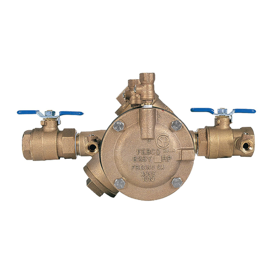
Series 825Y
operating or servicing this equipment.
Series 826YD
3
/
-2") . . . . . . . . . . . . . . . . . . . . . . . 11, 12, 13
4
3
/
-2") . . . . . . . . . . . . . . . . . . 14, 15
4
3
/
-2") . . . . . . . . . . . . . . . . . . . . . . . . . . . . . . . 15
4
1
/
-3") . . . . . . . . . . 16, 17
2
1
/
-10") . . . . . . . . . . . . . . . . . 20, 21
2
1
/
-10") . . . . . . . . . . . . . . . . . . . . . . . . . . . . . . 21
2
1
/
-10") . . . . . . . . . . . . . . . . . 30
2
IOM-F-825_826
Series 825YA
1
/
-10") 28, 29
2

Advertisement

Table of Contents
loading
Need help?

Need help?

Do you have a question about the 825YA and is the answer not in the manual?

Questions and answers

Ahdy
May 26, 2025

How can I buy a backflow preventer is a 3/4 inch Febco 825YA. It must be YA.

Bill Hansen
May 2, 2025

Can I purchase the rubber boots that cover the valves

Subscribe to Our Youtube Channel

Summary of Contents for Febco 825YA

  • Page 1: Table Of Contents

    I N S T A L L A T I O N , O P E R A T I O N , M A I N T E N A N C E Operation and Maintenance Manual Reduced Pressure Backflow Prevention Assemblies Models 825Y, 825YA, 825, 825D, 825YD & 826YD Series 825YA Series 825Y...
  • Page 2: Features And Operating Procedures

    The FEBCO Model 825 sizes 21/2–10" were manufactured with sure side is hydraulically connected to the reduced pressure zone, cast iron. The FEBCO Model 825 Type D and 825 Type YD sizes thus the relief valve remains closed during normal operation. The 21/2"–10"...
  • Page 3: Installation Guidelines

    MAINTENANCE MANUAL MODELS 825Y, 825YA, 825, 825D, 825YD & 826YD Installation Guidelines Proper installation of the assembly is essential to the protection of the water supply 1. The assembly should be installed in a horizontal position with a minimum clearance of 12" between the relief valve discharge port and floor or grade, and a minimum of 18"...
  • Page 4: Freeze Protection Procedures

    MAINTENANCE MANUAL MODELS 825Y, 825YA, 825, 825D, 825YD & 826YD Freeze Protection for the winter to prevent freeze damage. Procedure 5c. The ball valves must be fully closed before the system is repressurized. OPEN AND CLOSE BALL VALVES SLOWLY The reduced pressure backflow prevention assembly is subject to TO PREVENT DAMAGE TO THE SYSTEM CAUSED BY damage if the internal water is allowed to freeze.
  • Page 5: Vandalism Protection Procedures

    MAINTENANCE MANUAL MODELS 825Y, 825YA, 825, 825D, 825YD & 826YD Vandalism Protection Procedure 1. If the unit is installed where vandalism may be a problem, the 2. A protective cage can be installed over the unit to discourage assembly should be protected and secured. On 3/4–2" units vandals.
  • Page 6: General Service Procedures

    MAINTENANCE MANUAL MODELS 825Y, 825YA, 825, 825D, 825YD & 826YD General Service Procedures General Service Instructions applicable to all models and sizes. 1. FEBCO backflow prevention assemblies can be serviced with commonly available tools and are designed for ease of mainte- nance.
  • Page 7: Troubleshooting Procedures And Guide

    MAINTENANCE MANUAL MODELS 825Y, 825YA, 825, 825D, 825YD & 826YD Troubleshooting Procedure With Differential Pressure Gauge Without Differential Pressure Gauge SYMPTOM NO. 1: SYMPTOMS NO. 1 AND NO. 2: CHECK DIFFERENTIAL ACROSS NO. 1 CHECK VALVE A) Close Gate Valve No. 2...
  • Page 8 MAINTENANCE MANUAL MODELS 825Y, 825YA, 825, 825D, 825YD & 826YD Troubleshooting Guide (Continued) SYMPTOM: CAUSE: SOLUTION: 4. Relief valve does not open above 2.0 psid during a. Outlet gate valve not closed completely. a. Check for debris blocking gate. fi eld testing.
  • Page 9: Field Testing Procedures

    MAINTENANCE MANUAL MODELS 825Y, 825YA, 825, 825D, 825YD & 826YD Field Testing Procedures Purpose of Test To test the operation of the DIFFERENTIAL PRESSURE RELIEF Test Check Valve 1 VALVE and CHECK VALVE. The check valve must be at least 3 psi more than the relief valve Equipment Required for Test opening pressure.
  • Page 10 MAINTENANCE MANUAL MODELS 825Y, 825YA, 825, 825D, 825YD & 826YD Field Testing Procedures (Continued) Restore Operation Test for the 826YD After testing restore all valves to their original positions. This device is tested with the same procedure as the Model 825YD.
  • Page 11 MAINTENANCE MANUAL MODELS 825Y, 825YA, 825, 825D, 825YD & 826YD Service Procedure 825Y and YA ( –2") 1. Check Valve Inspection/Repair Model 825Y 2. Check Valve Seat Replacement Model 825Y (¾ –2") (See Figure No. 11) –2") (See Figure No. 11) a.
  • Page 12: Service Procedures Model 825Y ( 3 / 4 -2")

    MAINTENANCE MANUAL MODELS 825Y, 825YA, 825, 825D, 825YD & 826YD Service Procedure 825Y and YA ( –2") (Continued) d. Close the #4, #3, and #2 test cocks and slowly open first 5. Relief Valve Seat Removal Model 825Y the inlet and then outlet shutoff valves and return the –2")
  • Page 13 MAINTENANCE MANUAL MODELS 825Y, 825YA, 825, 825D, 825YD & 826YD Service Procedure 825Y and YA ( –2") (Cont.) 6. Relief Valve Reassembly Model 825Y ( –2") (See Figure No. 11) a. Lubricate the seat ring o-ring with FDA approved lubricant and thread seat ring into the valve body until seated.
  • Page 14: Parts Lists And Part Numbers Model 825Y ( 3 / 4 -2")

    MAINTENANCE MANUAL MODELS 825Y, 825YA, 825, 825D, 825YD & 826YD Model 825Y and YA ( –2") Parts Model 825Y & YA Part Numbers (Sizes ¾–2”) ITEM SIZE SIZE SIZE SIZE SIZE DESCRIPTION QTY.* ¾" 1" 1¼" 1½" 2" Bushing 500-290...
  • Page 15: Exploded View Of Model 825Y ( 3 / 4 -2")

    MAINTENANCE MANUAL MODELS 825Y, 825YA, 825, 825D, 825YD & 826YD Model 825Y, 825YR and YA ( –2") Parts (Cont.) Assemblies / Kits: Model 825Y & YA SIZE SIZE SIZE SIZE SIZE DESCRIPTION QT Y . * " 1" " "...
  • Page 16: Service Procedures Models 825, 825D And 825Yd (2 -3")

    MAINTENANCE MANUAL MODELS 825Y, 825YA, 825, 825D, 825YD & 826YD Service Procedures 825, 825D, 825YD and 826YD –3") 1. Check Valve Disassembly Models 825, 825D 3a. Valve Seat Removal (Sizes 2½ –3") and 825YD (Sizes 2 –3") (See Figure No. 13) Threaded-in Seat Ring Type Models Model 825 (See Figure No.
  • Page 17 MAINTENANCE MANUAL MODELS 825Y, 825YA, 825, 825D, 825YD & 826YD Service Procedures 825, 825D, 825YD and 826YD –3") (Continued) 3b. Valve Seat Removal (Sizes 2½ –3") Bolted in 5. Check Valve Reassembly (Sizes 2½ –3") Seat Ring Type Models 825D & 825YD (See Figures No.
  • Page 18: Service Procedures Models 825, 825D And 825Yd (4-10")

    MAINTENANCE MANUAL MODELS 825Y, 825YA, 825, 825D, 825YD & 826YD Service Procedures 825, 825D and 825YD (4–10") 1. Check Valve Disassembly (Sizes 4–10") (See Figures No. 15 & 16) a. Slowly close outlet gate valve then slowly close inlet gate valve.
  • Page 19 MAINTENANCE MANUAL MODELS 825Y, 825YA, 825, 825D, 825YD & 826YD Service Procedures 825, 825D and 825YD (4–10") (Continued) d. Un-thread capscrew (Item 7A) using " hex socket. 4b. Valve Seat Removal (Sizes 4–10") Bolted in Seat Ring Type Model 825D and 825YD (See Figure No.
  • Page 20: Parts Lists And Part Numbers Model 825 (2 -10")

    MAINTENANCE MANUAL MODELS 825Y, 825YA, 825, 825D, 825YD & 826YD Model 825 (2 –10") Parts Check Valve Body: Model 825 ITEM SIZE SIZE SIZE SIZE SIZE SIZE DESCRIPTION QT Y. * 2½" 3" 4" 6" 8" 10" 780-273 780-274 780-275...
  • Page 21: Exploded View Of Model 825 (2 -10")

    MAINTENANCE MANUAL MODELS 825Y, 825YA, 825, 825D, 825YD & 826YD Model 825 (2 –10") Parts (Continued) Assemblies / Kits: Model 825 SIZE SIZE SIZE SIZE SIZE SIZE DESCRIPTION " 3" 4" 6" 8" 10" 905-526 905-100 905-101 905-101 905-522 905-522...
  • Page 22: Parts Lists And Part Numbers Models 825D And 825Yd

    MAINTENANCE MANUAL MODELS 825Y, 825YA, 825, 825D, 825YD & 826YD Model 825 Type D and YD (2 –10") Parts Check Valve Body: Model 825D & 825YD ITEM SIZE SIZE SIZE SIZE SIZE SIZE DESCRIPTION QTY .* 2½" 3" 4" 6"...
  • Page 23: Exploded View Models 825D And 825Yd

    MAINTENANCE MANUAL MODELS 825Y, 825YA, 825, 825D, 825YD & 826YD Model 825D and 825YD (2 –10") Figure No. 14 42A* 1, 1A 43A* 41A* 41A* 41B* Relief Valve for Model 825YD (see Figure No.18 on page 26 for exploded view) * Denotes Commercial Parts Available (see page 31-33).
  • Page 24 MAINTENANCE MANUAL MODELS 825Y, 825YA, 825, 825D, 825YD & 826YD Model 825 Type D and YD (2 –10") Parts Assemblies / Kits: Model 825D Assemblies / Kits: Model 825YD SIZE SIZE SIZE SIZE SIZE SIZE DESCRIPTION " 3" 4" 6"...
  • Page 25: Parts List And Exploded View Of Model 825D And 825Yd Check Assembly 24 Parts List And Exploded View Of Model 825 And 825D Relief Valve

    MAINTENANCE MANUAL MODELS 825Y, 825YA, 825, 825D, 825YD & 826YD Model 825 and 825D (2 –10") Parts Relief Valve Body: Model 825 & 825D ITEM SIZE SIZE SIZE SIZE SIZE SIZE DESCRIPTION QTY.* 2½" 3" 4" 6" 8" 10" 780-372...
  • Page 26: Parts List And Exploded View Of Model 825Yd Relief Valve

    MAINTENANCE MANUAL MODELS 825Y, 825YA, 825, 825D, 825YD & 826YD Model 825 Type YD (2 –10") Parts Relief Valve Body: Model 825YD Relief Valve Model 825YD Figure No. 18 39** 905-104 Relief Valve Module * Denotes Commercial Parts Available (see page 31-33).
  • Page 27: Parts List And Exploded View Of Model 826Yd Relief Valve And Bypass

    MAINTENANCE MANUAL MODELS 825Y, 825YA, 825, 825D, 825YD & 826YD Model 826 Type YD (2 –10") Parts Relief Valve with Bypass: Model 826YD SIZE SIZE SIZE SIZE SIZE SIZE DESCRIPTION 2½" 3" 4" 6" 8" 10" 780-349 780-350 630-142 630-143...
  • Page 28 MAINTENANCE MANUAL MODELS 825Y, 825YA, 825, 825D, 825YD & 826YD Service Procedures Relief Valve 825, 825D and 825YD (2 –10") 1a. Relief Valve Disassembly Non-Modular Type 6. Reconnect copper tubing to relief valve. Relief Valve Models 825 and 825D 7. Slowly open inlet shut-off valve and bleed air by opening first test (See Figures No.
  • Page 29 MAINTENANCE MANUAL MODELS 825Y, 825YA, 825, 825D, 825YD & 826YD Service Procedures Relief Valve 825, 825D and 825YD (2 –10") (Cont.) the upper guide (Item 32). Remove the slip ring (Item 27a) and inner diaphragm (item 27). Inspect, clean and replace parts as required.
  • Page 30: Service Procedure Relief Valve Models 825, 825D And 825Yd (2 Spring Removal Tool Instructions Model 825 (2 -10")

    MAINTENANCE MANUAL MODELS 825Y, 825YA, 825, 825D, 825YD & 826YD Spring Removal Tool Figure No. 20 Dimensions (Inches) 1/2" Steel 1" DIA "C" DIA 2 PL "S Plate Valve (Min) S ize 4" - 13 6" - 1 1 8"...
  • Page 31 MAINTENANCE MANUAL MODELS 825Y, 825YA, 825, 825D, 825YD & 826YD MAINTENANCE MANUAL MODELS 825Y, 825YA, 825, 825D, 825YD & 826YD...
  • Page 32: Commercially Available Parts Lists

    MAINTENANCE MANUAL MODELS 825Y, 825YA, 825, 825D, 825YD & 826YD...
  • Page 33 MAINTENANCE MANUAL MODELS 825Y, 825YA, 825, 825D, 825YD & 826YD MAINTENANCE MANUAL MODELS 825Y, 825YA, 825, 825D, 825YD & 826YD...
  • Page 34: How To Order Parts

    MAINTENANCE MANUAL MODELS 825Y, 825YA, 825, 825D, 825YD & 826YD How to Order Repair Parts 1) Locate item number and kit number in this maintenance manual. 2) Verify the size of the valve the parts are to be used on.

This manual is also suitable for:

825y825d825826yd825yd

Table of Contents

Save PDF