Febco 825YA Series Installation Instructions
Reduced pressure zone assemblies
Hide thumbs
Also See for 825YA Series:
- Installation operation & maintenance (34 pages) ,
- Installation instructions (2 pages) ,
- Installation instructions (2 pages)
Advertisement
I N S T A L L A T I O N I N S T R U C T I O N S
Installation Instructions
1. Consult local codes for specific installation requirements and restrictions applicable to
your area. It is recommended that system supply pressure be at least 20psi (138 kPa).
2. These instructions apply to the Series 825YA, sizes
bly should be installed in the horizontal position with the relief valve on the side.
3. Approved flow directions indicated above may be achieved by removing the two bolts
at the inlet or outlet adapter flange and rotating the ball valve/adapter assembly into
the desired configuration shown.
4. THE VALVE ASSEMBLY MUST BE INSTALLED WHERE RELIEF VALVE DISCHARGE
WILL BE ACCEPTABLE, OR WHERE RELIEF VALVE DISCHARGE CAN BE COM-
PLETELY DRAINED. The valve assembly must be installed where it is accessible for
periodic testing and maintenance. Clearances shown in the installation views apply to
exterior, interior and pit/vault installations and are only recommendations. These mini-
mums do not apply to removable protective enclosures. Refer to local codes for actual
requirements in your area.
NOTE: The gap drain is not designed to catch the maximum discharge possible from
the relief valve. The installation of FEBCO air gap with the drain line terminating above
a floor drain will handle any normal discharge or nuisance spitting through the relief
valve. However, floor drain size may need to be designed to prevent water damage
caused by a catastrophic failure condition. Do not reduce the size of the drain line
from the air gap fitting.
5. PRIOR TO INSTALLING THE VALVE INTO THE LINE, FLUSH THE SUPPLY LINE OF
ALL FOREIGN MATERIAL. Failure to flush the supply line may cause the check
valves to become fouled and require disassembly and cleaning.
6. After installation SLOWLY fill the assembly with water and bleed air from the body
using the # 3 and # 4 test cocks. Test the valve assembly to ensure correct operation.
NOTE: All assemblies are tested at the factory for proper operation and leakage. If the
valve does not pass the field test, it is most likely due to a fouled check valve. This is
not covered by the factory warranty. The valve cover(s) must be removed and the
check seats inspected and cleaned. Any damage or improper operation caused by
pipeline debris or improper installation/start-up is not included in the factory warranty.
In case of a possible warranty claim, contact your local supplier or FEBCO
Representative. DO NOT REMOVE THE VALVE ASSEMBLY FROM THE PIPELINE.
7. The assembly must be protected from freezing and excessive pressure increases.
Thermal expansion or water hammer can cause pressure increases. These excessive
pressure situations must be eliminated to protect the valve and system from
possible damage.
8. Plastic test cock plugs and tethers are provided (loose in box) for areas that
require them.
Figure 2
Figure 1
Vertical Up Flow In
Horizontal Flow In
Vertical Down Flow Out
Vertical Down Flow Out
Reduced Pressure Zone Assemblies
3
⁄
"- 2" (20 - 50mm) only. The assem-
4
Figure 3
Vertical Up Flow In
Horizontal Flow Out
Horizontal Flow Out
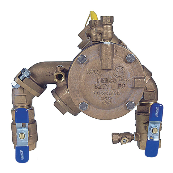
Series 825YA
Sizes:
18" (450mm) Min
12" (300mm) Min
12" (300mm) Min
(Refer to Local Codes)
Figure 4
Horizontal Flow In
IS-F-825YA/RP
3
⁄
" – 2" (20 – 50mm)
4
6" (150mm) Min
Advertisement
Table of Contents

Related Manuals for Febco 825YA Series


Summary of Contents for Febco 825YA Series
- Page 1 NOTE: The gap drain is not designed to catch the maximum discharge possible from the relief valve. The installation of FEBCO air gap with the drain line terminating above a floor drain will handle any normal discharge or nuisance spitting through the relief 18"...
- Page 2 Eliminate surges Limited Warranty: FEBCO warrants each product to be free from defects in material and workmanship under normal usage for a period of one year from the date of original shipment. In the event of such defects within the warranty period, the Company will, at its option, replace or recondition the product without charge. This shall constitute the sole and exclusive remedy for breach of warranty, and...
Need help?
Do you have a question about the 825YA Series and is the answer not in the manual?
Questions and answers