Triton 9600 Installation And Service Manual

Triton 9600 Installation And Service Manual

Single-cassette cash dispenser
Hide thumbs Also See for 9600:
Table of Contents

Advertisement

Quick Links

C
H
ORPORATE
EADQUARTERS
522 E. Railroad Street
Long Beach, MS 39560
PHONE: (228) 868-1317
FAX: (228) 868-0437
Copyright © 2000 Triton Systems , Inc. All rights reserved. No part of this publication may be
reproduced, transmitted, transcribed, stored in a retrieval system, or translated into any human or
computer language, in any form, by any means whatsoever, without the express written permission
of Triton Systems, Inc.
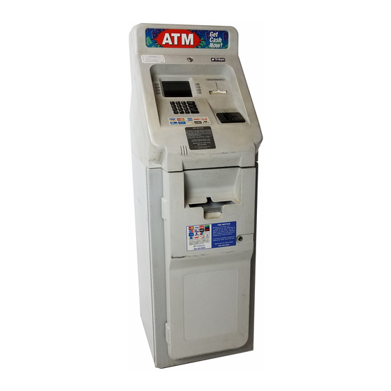
S
-C
INGLE
C
D
ASH
ISPENSER
(M
9600/9601/9620/9621)
ODELS
INSTALLATION AND SERVICE
MANUAL
Version 4.1
TDN 07103-00034 03/00
TRITON SYSTEMS, INC.
:
COPYRIGHT NOTICE
ASSETTE
RMA (R
M
ETURN
ATERIAL
R
A
:
ETURN
DDRESS
21405 B Street
Long Beach, MS 39560
A
)
UTHORIZATION

Advertisement

Table of Contents
loading
Need help?

Need help?

Do you have a question about the 9600 and is the answer not in the manual?

Questions and answers

Subscribe to Our Youtube Channel

Summary of Contents for Triton 9600

  • Page 1 FAX: (228) 868-0437 COPYRIGHT NOTICE Copyright © 2000 Triton Systems , Inc. All rights reserved. No part of this publication may be reproduced, transmitted, transcribed, stored in a retrieval system, or translated into any human or computer language, in any form, by any means whatsoever, without the express written permission...
  • Page 2 9600/9601/9620/9621 INGLE ASSETTE ISPENSER NSTALLATION AND ODELS ERVICE ANUAL FCC COMPLIANCE Warning: Changes or modifications to this unit not expressly approved by the party responsible for compliance could void the user’s authority to operate the equipment. Note: This equipment has been tested and found to comply with the limits for a Class A digital device, persuant to Part 15 of FCC Rules.
  • Page 3 9600/9601/9620/9621 INGLE ASSETTE ISPENSER NSTALLATION AND ODELS ERVICE ANUAL NOTICE: The Industry Canada label identifies certified equipment. This certification means that the equipment meets telecommunications network protective, operational and safety requirements as prescribed in the appropriate Terminal Equipment Technical Requirements document(s). The Department does not guarantee the equipment will operate to the user’s satisfaction.
  • Page 4 9600/9601/9620/9621 INGLE ASSETTE ISPENSER NSTALLATION AND ODELS ERVICE ANUAL AVIS: L’étiquette d’Industrie Canada identific le matériel homologué. Cette étiquette certifie que le matériel est conforme aux normes de protection, d’exploitation et de sécurité des réseaux de télécommunications, comme le prescrivent les documents concernant les exigences techniques relatives au matériel terminal.
  • Page 5: Table Of Contents

    9600/9601/9620/9621 INGLE ASSETTE ISPENSER NSTALLATION AND ODELS ERVICE ANUAL ONTENTS 1- I ......................1-2 ECTION NTRODUCTION ’ ......................1-2 ANUAL ....................1-2 ARNING AUTIONS AND OTES 2 - I ..................... 2-1 ECTION NSTALLATION AND ETUP ..................... 2-2 NPACKING ISPENSER ................ 2-3...
  • Page 6 9600/9601/9620/9621 INGLE ASSETTE ISPENSER NSTALLATION AND ODELS ERVICE ANUAL ONTENTS : JOURNAL ......................2-37 UNCTION : PRINT JOURNAL ..................2-38 UNCTION : CLEAR JOURNAL ..................2-39 UNCTION : PRINT LAST X ENTRIES ................2-40 UNCTION : PASSWORD MAINTENANCE ................. 2-41 UNCTION : MASTER PASSWORD ................
  • Page 7 : PRIMARY ALARM NUMBER ..........2-111 UNCTION : BACKUP ALARM NUMBER ..........2-112 UNCTION : ENABLE/DISABLE CALL BACK ..........2-113 UNCTION : ENABLE/DISABLE TRITON CONNECT ......... 2-114 UNCTION : ATM MONITORING ..............2-115 UNCTION : STATUS MONITORING ............2-116 UNCTION : HEARTBEAT MESSAGE ............
  • Page 8 9600/9601/9620/9621 INGLE ASSETTE ISPENSER NSTALLATION AND ODELS ERVICE ANUAL ONTENTS : DATE/TIME FUNCTIONS ................2-131 UNCTION : SET DATE FORMAT ................. 2-132 UNCTION : SET DATE / TIME ..................2-133 UNCTION : SET DATE ................... 2-134 UNCTION : SET TIME .................... 2-135 UNCTION : TRANSACTION TYPES ..................
  • Page 9 9600/9601/9620/9621 INGLE ASSETTE ISPENSER NSTALLATION AND ODELS ERVICE ANUAL ONTENTS 133 - ..........................3-14 134 - ..........................3-14 135 - ..........................3-14 136 - ..........................3-14 138 - ..........................3-15 139 - ..........................3-16 140 - ..........................3-16 141 - ..........................3-16 142 - ..........................
  • Page 10 9600/9601/9620/9621 INGLE ASSETTE ISPENSER NSTALLATION AND ODELS ERVICE ANUAL ONTENTS 203 - ..........................3-20 205 - ..........................3-20 206 - ..........................3-20 209 - ..........................3-20 210 - ..........................3-20 ..................3-21 RROR ODES ISPENSER 32 (20 ) - ........................3-22 33 (21 ) - ........................
  • Page 11 ............3-55 EMOVING NSTALLING LECTRONIC OURNAL LED O ................3-57 ISPENSING ECHANISM PERATION APPENDIX A - C ................A-1 ISPENSER PECIFICATIONS 9600 S ) ..........A-2 ODEL INGLE ASSETTE ISPENSER RONT CCESS 9601 S ) ..........A-5 ODEL INGLE ASSETTE ISPENSER...
  • Page 12 9600/9601/9620/9621 INGLE ASSETTE ISPENSER NSTALLATION AND ODELS ERVICE ANUAL ONTENTS ..................F-4 TARTING THE OFTWARE OWNLOAD TRICOMM ................F-4 OADING THE OFTWARE SING ..........F-5 REPARING THE ISPENSER FOR ROGRAM OWNLOADING APPENDIX G - W ............G-1 ARRANTY AND EPAIR...
  • Page 13: Section 1 Introduction

    ECTION NTRODUCTION...
  • Page 14: Hat His Anual

    NTRODUCTION ’ ANUAL This manual contains important information you will need to install and maintain your Triton Systems Cash Dispenser (Models 9600/9601/9620/9621). Additional information pertaining to the operation of your Cash Dispenser is included in the Single-Cassette Cash Dispenser Operation Manual (Models 9600/9601/9620/9621).
  • Page 15: Autions And

    9600/9601/9620/9621 ODELS INGLE ASSETTE ISPENSER NSTALLATION AND ERVICE ANUAL 1 - I ECTION NTRODUCTION ARNINGS AUTIONS AND OTES Warnings, cautions, and notes provide information which you need to consider. A WARNING indicates that a certain action can potentially give you an electrical shock.
  • Page 17: Section 2 - Installation And Setup

    ECTION NSTALLATION AND ETUP...
  • Page 18: Npacking The Cash Ispenser

    8. Turn the handle on the locking mechanism to open the front enclosure door. 9. Remove the accessory kit from inside the bottom enclosure and open and inspect the contents. Check the contents against the enclosed packing list. Report any missing parts to Triton immediately.
  • Page 19: Securing The Cash Dispenser T O The Floor

    9600/9601/9620/9621 ODELS INGLE ASSETTE ISPENSER NSTALLATION AND ERVICE ANUAL 2 - I ECTION NSTALLATION AND ETUP The unit was shipped with the combination lock unlocked. If it has become locked, a manual lock can be unlocked by turning the dial at least four complete revolutions counter-clockwise (to the left), stopping on 50 at the main (opening) index.
  • Page 20: Installing The Dispensing Mechanism

    Secure the DB25 cable to the dispenser with two screws attached to the connector. Insert the Molex power plug attached to cable 9600-0013 into the connector marked PL2. This plug is keyed so that it can only be inserted in one direction.
  • Page 21: Completing

    9600/9601/9620/9621 ODELS INGLE ASSETTE ISPENSER NSTALLATION AND ERVICE ANUAL 2 - I ECTION NSTALLATION AND ETUP OMPLETING HYSICAL NSTALLATION 1 . The Cash Dispenser is quite tolerant of power line variations, primarily because of its built- in surge suppressor. However, AC power for the terminal should come from a dedicated source with an isolated ground.
  • Page 22 9600/9601/9620/9621 INGLE ASSETTE ISPENSER NSTALLATION AND ODELS ERVICE ANUAL 2 - I ECTION NSTALLATION AND ETUP Connect the phone cord into the wall mounted modular phone jack. The phone line used for the Cash Dispenser should not be shared with any other device.
  • Page 23: Test Dispense

    9600/9601/9620/9621 ODELS INGLE ASSETTE ISPENSER NSTALLATION AND ERVICE ANUAL 2 - I ECTION NSTALLATION AND ETUP ISPENSE The test dispense command instructs the dispenser to dispense one note into the reject area of the cassette. This test exercises the dispenser except that no bills actually leave the mechanism. This command returns three data bytes.
  • Page 24 9600/9601/9620/9621 INGLE ASSETTE ISPENSER NSTALLATION AND ODELS ERVICE ANUAL 2 - I ECTION NSTALLATION AND ETUP S ’ RITON YSTEMS...
  • Page 25: Setting The Combination Lock

    The manual and electronic combination locks are set to “factory default values” that are well known to anyone that has ever installed a Triton Systems Cash Dispenser. For obvious security reasons, the combination must be changed to new numbers that are only known by persons requiring access to the Security Container.
  • Page 26: Ccessing The Management Functions Enu

    9600/9601/9620/9621 INGLE ASSETTE ISPENSER NSTALLATION AND ODELS ERVICE ANUAL 2 - I ECTION NSTALLATION AND ETUP B. When the screen “PLEASE ENTER THE SIX-DIGIT EPROM ACCESS CODE” is displayed, enter the factory default access code “123456”. Entering this code will display the “miniATM MAIN MENU.”...
  • Page 27: Function Availability

    9600/9601/9620/9621 ODELS INGLE ASSETTE ISPENSER NSTALLATION AND ERVICE ANUAL 2 - I ECTION NSTALLATION AND ETUP Figure 2-5. The TOP MENU Screen. Figure 2-4. The PASSWORD entry screen. The MASTER PASSWORD allows access to all functions performed with the ADMINISTRATION password plus access to the Cash Dispenser configuration functions.
  • Page 28: Management Functions Chart

    9600/9601/9620/9621 INGLE ASSETTE ISPENSER NSTALLATION AND ODELS ERVICE ANUAL 2 - I ECTION NSTALLATION AND ETUP Management Functions Chart RITON YSTEMS 2-12...
  • Page 29: Function : Management Functions

    9600/9601/9620/9621 INGLE ASSETTE ISPENSER NSTALLATION AND ODELS ERVICE ANUAL 2 - I ECTION NSTALLATION AND ETUP : MANAGEMENT FUNCTIONS UNCTION : N/A ACTORY EFAULT CCESS NSTRUCTIONS Select the MANAGEMENT FUNCTIONS option from the Top Menu. ESCRIPTION The MANAGEMENT FUNCTIONS menu allows the terminal operator to access the following functions: 1.) CLOSE...
  • Page 30: Function : Close

    9600/9601/9620/9621 ODELS INGLE ASSETTE ISPENSER NSTALLATION AND ERVICE ANUAL 2 - I ECTION NSTALLATION AND ETUP : CLOSE UNCTION : N/A ACTORY EFAULT CCESS NSTRUCTIONS Select the CLOSE option from the MANAGEMENT FUNCTIONS screen to view the options available from the SELECT CLOSE FUNCTION menu.
  • Page 31: Function : Schedule Close

    NOTE: The close information will be written to the Electronic Journal, allowing it to be printed out, or retrieved by a remote computer equipped with Triton Connect software (version 3.0 or later). Day Close reports initiated by this function will not be printed by the receipt printer.
  • Page 32: Function : Change Schedule

    9600/9601/9620/9621 ODELS INGLE ASSETTE ISPENSER NSTALLATION AND ERVICE ANUAL 2 - I ECTION NSTALLATION AND ETUP : CHANGE SCHEDULE UNCTION : N/A ACTORY EFAULT CCESS NSTRUCTIONS 1.) Select CLOSE from the MANAGEMENT FUNCTION screen. 2.) Select SCHEDULE CLOSE. 3.) Select CHANGE SCHEDULE.
  • Page 33: Function : Trial Cassette Balance

    9600/9601/9620/9621 INGLE ASSETTE ISPENSER NSTALLATION AND ODELS ERVICE ANUAL 2 - I ECTION NSTALLATION AND ETUP : TRIAL CASSETTE BALANCE UNCTION : N/A ACTORY EFAULT CCESS NSTRUCTIONS 1.) Select CLOSE from the MANAGEMENT FUNCTION screen. 2.) Select TRIAL CASSETTE BALANCE.
  • Page 34: Function : Trial Close

    9600/9601/9620/9621 ODELS INGLE ASSETTE ISPENSER NSTALLATION AND ERVICE ANUAL 2 - I ECTION NSTALLATION AND ETUP : TRIAL CLOSE UNCTION : N/A ACTORY EFAULT CCESS NSTRUCTIONS 1.) Select CLOSE from the MANAGEMENT FUNCTIONS screen. 2.) Select TRIAL CLOSE. ESCRIPTION The TRIAL CLOSE function is used during the daily close procedure.
  • Page 35: Function : Day Close

    9600/9601/9620/9621 INGLE ASSETTE ISPENSER NSTALLATION AND ODELS ERVICE ANUAL 2 - I ECTION NSTALLATION AND ETUP : DAY CLOSE UNCTION : N/A ACTORY EFAULT CCESS NSTRUCTIONS 1.) Select CLOSE from the MANAGEMENT FUNCTIONS screen. 2.) Select DAY CLOSE. ESCRIPTION The DAY CLOSE Function is used to complete daily balancing of the Cash Dispenser with the processor.
  • Page 36: Function : Send Terminal Totals

    9600/9601/9620/9621 ODELS INGLE ASSETTE ISPENSER NSTALLATION AND ERVICE ANUAL 2 - I ECTION NSTALLATION AND ETUP : SEND TERMINAL TOTALS UNCTION : OFF ACTORY EFAULT CCESS NSTRUCTIONS 1.) Select CLOSE from the MANAGEMENT FUNCTION screen. 2.) Select SEND TERMINAL TOTALS.
  • Page 37: Function : Enter Qty. In Cassette

    9600/9601/9620/9621 INGLE ASSETTE ISPENSER NSTALLATION AND ODELS ERVICE ANUAL 2 - I ECTION NSTALLATION AND ETUP : ENTER QTY. IN CASSETTE UNCTION : ‘0’ ACTORY EFAULT CCESS NSTRUCTIONS 1.) Select CLOSE from the MANAGEMENT FUNCTION screen. 2.) Select ENTER QTY. IN CASSETTE.
  • Page 38: Function : Cassette Close

    9600/9601/9620/9621 ODELS INGLE ASSETTE ISPENSER NSTALLATION AND ERVICE ANUAL 2 - I ECTION NSTALLATION AND ETUP : CASSETTE CLOSE UNCTION : N/A ACTORY EFAULT CCESS NSTRUCTIONS 1.) Select CLOSE from the MANAGEMENT FUNCTION screen. 2.) Select CASSETTE CLOSE. ESCRIPTION The CASSETTE CLOSE function is used to complete the balancing of a specific currency cassette of the Cash Dispenser.
  • Page 39: Function : Diagnostics

    9600/9601/9620/9621 INGLE ASSETTE ISPENSER NSTALLATION AND ODELS ERVICE ANUAL 2 - I ECTION NSTALLATION AND ETUP : DIAGNOSTICS UNCTION : N/A ACTORY EFAULT CCESS NSTRUCTIONS Select DIAGNOSTICS from the MANAGEMENT FUNCTIONS screen. ESCRIPTION Select one of the following to perform the appropriate DIAGNOSTICS test: •...
  • Page 40: Function : Status

    9600/9601/9620/9621 ODELS INGLE ASSETTE ISPENSER NSTALLATION AND ERVICE ANUAL 2 - I ECTION NSTALLATION AND ETUP : STATUS UNCTION : N/A ACTORY EFAULT CCESS NSTRUCTIONS 1.) Select DIAGNOSTICS from the MANAGE- MENT FUNCTIONS screen. 2.) Select the STATUS option. ESCRIPTION The STATUS command is used to check the status of four functional areas of the dispensing mechanism.
  • Page 41: Function : Purge

    9600/9601/9620/9621 INGLE ASSETTE ISPENSER NSTALLATION AND ODELS ERVICE ANUAL 2 - I ECTION NSTALLATION AND ETUP : PURGE UNCTION : N/A ACTORY EFAULT CCESS NSTRUCTIONS 1.) Select DIAGNOSTICS from the MANAGE- MENT FUNCTIONS screen. 2.) Select the PURGE option. ESCRIPTION The purge command instructs the dispenser to remove all documents from the feed path.
  • Page 42: Function : Test Dispense

    9600/9601/9620/9621 ODELS INGLE ASSETTE ISPENSER NSTALLATION AND ERVICE ANUAL 2 - I ECTION NSTALLATION AND ETUP : TEST DISPENSE UNCTION : N/A ACTORY EFAULT CCESS NSTRUCTIONS 1.) Select DIAGNOSTICS from the MANAGE- MENT FUNCTIONS screen. 2.) Select the TEST DISPENSE option.
  • Page 43 Memory Expansion Card, it can be accomplished from either the local terminal or through commands downloaded from a Triton Connect Host Computer. CAUTION: Formatting a Memory Expansion Card will erase all files stored on the card. Do not format a Memory Expansion Card unless you have the capability to download files to the terminal.
  • Page 44: Function : Test Receipt Printer

    9600/9601/9620/9621 ODELS INGLE ASSETTE ISPENSER NSTALLATION AND ERVICE ANUAL 2 - I ECTION NSTALLATION AND ETUP : TEST RECEIPT PRINTER UNCTION : N/A ACTORY EFAULT CCESS NSTRUCTIONS 1.) Select DIAGNOSTICS from the MANAGE- MENT FUNCTIONS screen. 2.) Select the TEST RECEIPT PRINTER option.
  • Page 45: Function : Version #'S

    9600/9601/9620/9621 INGLE ASSETTE ISPENSER NSTALLATION AND ODELS ERVICE ANUAL 2 - I ECTION NSTALLATION AND ETUP : VERSION #’S UNCTION : N/A ACTORY EFAULT CCESS NSTRUCTIONS 1.) Select DIAGNOSTICS from the MANAGE- MENT FUNCTIONS screen. 2.) Select the VERSION #’S option.
  • Page 46: Function : More Diagnostics

    9600/9601/9620/9621 ODELS INGLE ASSETTE ISPENSER NSTALLATION AND ERVICE ANUAL 2 - I ECTION NSTALLATION AND ETUP : MORE DIAGNOSTICS UNCTION : N/A ACTORY EFAULT CCESS NSTRUCTIONS 1.) Select DIAGNOSTICS from the MANAGE- MENT FUNCTIONS screen. 2.) Select the MORE DIAGNOSTICS option.
  • Page 47: Function : Reset/Test Modem

    9600/9601/9620/9621 INGLE ASSETTE ISPENSER NSTALLATION AND ODELS ERVICE ANUAL 2 - I ECTION NSTALLATION AND ETUP : RESET/TEST MODEM UNCTION : N/A ACTORY EFAULT CCESS NSTRUCTIONS 1.) Select DIAGNOSTICS from the MANAGE- MENT FUNCTIONS screen. 2.) Select MORE DIAGNOSTICS. 3.) Select the RESET/TEST MODEM option.
  • Page 48: Function : Scan Card

    9600/9601/9620/9621 ODELS INGLE ASSETTE ISPENSER NSTALLATION AND ERVICE ANUAL 2 - I ECTION NSTALLATION AND ETUP : SCAN CARD UNCTION : N/A ACTORY EFAULT CCESS NSTRUCTIONS 1.) Select DIAGNOSTICS from the MANAGE- MENT FUNCTIONS screen. 2.) Select MORE DIAGNOSTICS. 3.) Select the SCAN CARD option.
  • Page 49: Function : Language/Idioma

    9600/9601/9620/9621 INGLE ASSETTE ISPENSER NSTALLATION AND ODELS ERVICE ANUAL 2 - I ECTION NSTALLATION AND ETUP : LANGUAGE/IDIOMA UNCTION : Country-specific ACTORY EFAULT CCESS NSTRUCTIONS Select the LANGUAGE/IDIOMA option from the MANAGEMENT FUNCTIONS screen to view the additional options available.
  • Page 50: Function : English/Ingles

    9600/9601/9620/9621 ODELS INGLE ASSETTE ISPENSER NSTALLATION AND ERVICE ANUAL 2 - I ECTION NSTALLATION AND ETUP ENGLISH/INGLES UNCTION : N/A ACTORY EFAULT CCESS NSTRUCTIONS 1.) Select the LANGUAGE/IDIOMA option from the MANAGEMENT FUNCTIONS screen. 2.) Select the ENGLISH/INGLES option. ESCRIPTION Choosing this function when the DISABLE CUST.
  • Page 51: Function : Spanish/Espanol

    9600/9601/9620/9621 INGLE ASSETTE ISPENSER NSTALLATION AND ODELS ERVICE ANUAL 2 - I ECTION NSTALLATION AND ETUP : SPANISH/ESPANOL UNCTION : N/A ACTORY EFAULT CCESS NSTRUCTIONS 1.) Select the LANGUAGE/IDIOMA option from the MANAGEMENT FUNCTIONS screen. 2.) Select the SPANISH/ESPANOL option.
  • Page 52: Function : Enable/Disable Cust. Option

    9600/9601/9620/9621 ODELS INGLE ASSETTE ISPENSER NSTALLATION AND ERVICE ANUAL 2 - I ECTION NSTALLATION AND ETUP : ENABLE/DISABLE CUST. OPTION UNCTION : ‘OPTION IS: DISABLED’ ACTORY EFAULT CCESS NSTRUCTIONS 1.) Select the LANGUAGE/IDIOMA option from the MANAGEMENT FUNCTIONS screen. 2.) Select either option, as appropriate: •...
  • Page 53: Function : Journal

    9600/9601/9620/9621 INGLE ASSETTE ISPENSER NSTALLATION AND ODELS ERVICE ANUAL 2 - I ECTION NSTALLATION AND ETUP : JOURNAL UNCTION : N/A ACTORY EFAULT CCESS NSTRUCTIONS Select JOURNAL from the options available at the MANAGEMENT FUNCTIONS screen. ESCRIPTION Select the JOURNAL function from the MANAGEMENT FUNCTIONS screen to: 1.) PRINT THE JOURNAL...
  • Page 54: Function : Print Journal

    9600/9601/9620/9621 ODELS INGLE ASSETTE ISPENSER NSTALLATION AND ERVICE ANUAL 2 - I ECTION NSTALLATION AND ETUP : PRINT JOURNAL UNCTION : N/A ACTORY EFAULT CCESS NSTRUCTIONS 1.) Select JOURNAL from the options available at the MANAGEMENT FUNCTIONS screen. 2.) Select the PRINT JOURNAL option to print all unaudited records stored in the Electronic Journal.
  • Page 55: Function : Clear Journal

    9600/9601/9620/9621 INGLE ASSETTE ISPENSER NSTALLATION AND ODELS ERVICE ANUAL 2 - I ECTION NSTALLATION AND ETUP : CLEAR JOURNAL UNCTION : N/A ACTORY EFAULT CCESS NSTRUCTIONS 1.) Select JOURNAL from the options available at the MANAGEMENT FUNCTIONS screen. 2.) Select the CLEAR JOURNAL option to mark...
  • Page 56: Function : Print Last X Entries

    9600/9601/9620/9621 ODELS INGLE ASSETTE ISPENSER NSTALLATION AND ERVICE ANUAL 2 - I ECTION NSTALLATION AND ETUP : PRINT LAST X ENTRIES UNCTION : N/A ACTORY EFAULT CCESS NSTRUCTIONS 1.) Select JOURNAL from the options available at the MANAGEMENT FUNCTIONS screen.
  • Page 57: Function : Password Maintenance

    9600/9601/9620/9621 INGLE ASSETTE ISPENSER NSTALLATION AND ODELS ERVICE ANUAL 2 - I ECTION NSTALLATION AND ETUP : PASSWORD MAINTENANCE UNCTION : N/A ACTORY EFAULT CCESS NSTRUCTIONS Select the PASSWORD MAINTENANCE option from the MANAGEMENT FUNCTIONS screen. ESCRIPTION The PASSWORD MAINTENANCE Function of MANAGEMENT FUNCTIONS menu allows access to menus for viewing and changing the following: 1.) MASTER PASSWORD...
  • Page 58: Function : Master Password

    9600/9601/9620/9621 ODELS INGLE ASSETTE ISPENSER NSTALLATION AND ERVICE ANUAL 2 - I ECTION NSTALLATION AND ETUP : MASTER PASSWORD UNCTION : ‘123456’ ACTORY EFAULT CCESS NSTRUCTIONS 1.) Select the PASSWORD MAINTENANCE option from the MANAGEMENT FUNCTIONS screen. 2.) Select the MASTER PASSWORD option.
  • Page 59: Function : Administration Password

    9600/9601/9620/9621 INGLE ASSETTE ISPENSER NSTALLATION AND ODELS ERVICE ANUAL 2 - I ECTION NSTALLATION AND ETUP : ADMINISTRATION PASSWORD UNCTION : ‘987654’ ACTORY EFAULT CCESS NSTRUCTIONS 1.) Select the PASSWORD MAINTENANCE option from the MANAGEMENT FUNC- TIONS screen. 2.) Select the ADMINISTRATION PASSWORD option.
  • Page 60: Function : Terminal Configuration

    9600/9601/9620/9621 ODELS INGLE ASSETTE ISPENSER NSTALLATION AND ERVICE ANUAL 2 - I ECTION NSTALLATION AND ETUP : TERMINAL CONFIGURATION UNCTION : N/A ACTORY EFAULT CCESS NSTRUCTIONS Select the TERMINAL CONFIGURATION option from the MANAGEMENT FUNCTIONS screen. ESCRIPTION The TERMINAL CONFIGURATION option provides access to functions that allow the following parameters to be viewed and changed: 1.) PRINTER SETTINGS...
  • Page 61: Function : Printer Settings

    9600/9601/9620/9621 INGLE ASSETTE ISPENSER NSTALLATION AND ODELS ERVICE ANUAL 2 - I ECTION NSTALLATION AND ETUP : PRINTER SETTINGS UNCTION : N/A ACTORY EFAULT CCESS NSTRUCTIONS 1.) Select the TERMINAL CONFIGURATION option from the MANAGEMENT FUNC- TIONS screen. 2.) Select the PRINTER SETTINGS option.
  • Page 62: Function : Set Print Length

    9600/9601/9620/9621 ODELS INGLE ASSETTE ISPENSER NSTALLATION AND ERVICE ANUAL 2 - I ECTION NSTALLATION AND ETUP : SET PRINT LENGTH UNCTION : ‘35’ ACTORY EFAULT CCESS NSTRUCTIONS 1.) Select the TERMINAL CONFIGURATION option from the MANAGEMENT FUNCTIONS screen. 2.) Select the PRINTER SETTINGS option.
  • Page 63: Function : Low Receipt Paper

    9600/9601/9620/9621 INGLE ASSETTE ISPENSER NSTALLATION AND ODELS ERVICE ANUAL 2 - I ECTION NSTALLATION AND ETUP : LOW RECEIPT PAPER UNCTION : ‘OUT OF SERVICE’ ACTORY EFAULT CCESS NSTRUCTIONS 1.) Select TERMINAL CONFIGURATION from the MANAGEMENT FUNCTIONS menu. 2.) Select the PRINTER SETTINGS option.
  • Page 64: Function : Printer Graphics

    The Printed Graphics feature can only be used when an optional Memory Expansion Card is installed in the terminal. Triton Connect Software Release 1.8 (or above) allows bit mapped graphics (in ‘.bmp’ format) to be downloaded to the terminal. This graphic will be printed on the receipt when the PRINTER GRAPHICS option has been ENABLED.
  • Page 65: Function : Random/Level Prize Coupons

    9600/9601/9620/9621 INGLE ASSETTE ISPENSER NSTALLATION AND ODELS ERVICE ANUAL 2 - I ECTION NSTALLATION AND ETUP : RANDOM/LEVEL PRIZE COUPONS UNCTION : N/A ACTORY EFAULT CCESS NSTRUCTIONS 1.) Select TERMINAL CONFIGURATION from the MANAGEMENT FUNCTIONS menu. 2.) Select RANDOM/LEVEL PRIZE COUPONS from the TERMINAL CONFIGURATION menu.
  • Page 66: Function : Enter Prize Level Msg

    9600/9601/9620/9621 ODELS INGLE ASSETTE ISPENSER NSTALLATION AND ERVICE ANUAL 2 - I ECTION NSTALLATION AND ETUP : ENTER LEVEL PRIZE MSG. UNCTION : NONE ACTORY EFAULT CCESS NSTRUCTIONS 1.) Select TERMINAL CONFIGURATION from the MANAGEMENT FUNCTIONS menu. 2.) Select RANDOM/LEVEL PRIZE COUPONS from the TERMINAL CONFIGURATION menu.
  • Page 67: Function : Enter Random Prize Msg

    9600/9601/9620/9621 INGLE ASSETTE ISPENSER NSTALLATION AND ODELS ERVICE ANUAL 2 - I ECTION NSTALLATION AND ETUP : ENTER RANDOM PRIZE MSG. UNCTION : NONE ACTORY EFAULT CCESS NSTRUCTIONS 1.) Select TERMINAL CONFIGURATION from the MANAGEMENT FUNCTIONS menu. 2.) Select RANDOM/LEVEL PRIZE COUPONS from the TERMINAL CONFIGURATION menu.
  • Page 68: Function : Enable/Disable Coupon Awards

    9600/9601/9620/9621 ODELS INGLE ASSETTE ISPENSER NSTALLATION AND ERVICE ANUAL 2 - I ECTION NSTALLATION AND ETUP : ENABLE/DISABLE COUPON AWARDS UNCTION : DISABLED ACTORY EFAULT CCESS NSTRUCTIONS 1.) Select TERMINAL CONFIGURATION from the MANAGEMENT FUNCTIONS menu. 2.) Select RANDOM/LEVEL PRIZE COUPONS from the TERMINAL CONFIGURATION menu.
  • Page 69: Function : Set Level Prize Amount

    9600/9601/9620/9621 INGLE ASSETTE ISPENSER NSTALLATION AND ODELS ERVICE ANUAL 2 - I ECTION NSTALLATION AND ETUP : SET LEVEL PRIZE AMOUNT UNCTION : ‘$0.00’ ACTORY EFAULT CCESS NSTRUCTIONS 1.) Select TERMINAL CONFIGURATION from the MANAGEMENT FUNCTIONS menu. 2.) Select RANDOM/LEVEL PRIZE COUPONS from the TERMINAL CONFIGURATION menu.
  • Page 70: Function : Set Random Winning

    9600/9601/9620/9621 ODELS INGLE ASSETTE ISPENSER NSTALLATION AND ERVICE ANUAL 2 - I ECTION NSTALLATION AND ETUP : SET RANDOM WINNING % UNCTION : ‘0%’ ACTORY EFAULT CCESS NSTRUCTIONS 1.) Select TERMINAL CONFIGURATION from the MANAGEMENT FUNCTIONS menu. 2.) Select RANDOM/LEVEL PRIZE COUPONS from the TERMINAL CONFIGURATION menu.
  • Page 71: Function : Change Messages

    9600/9601/9620/9621 INGLE ASSETTE ISPENSER NSTALLATION AND ODELS ERVICE ANUAL 2 - I ECTION NSTALLATION AND ETUP : CHANGE MESSAGES UNCTION : N/A ACTORY EFAULT CCESS NSTRUCTIONS 1.) Select TERMINAL CONFIGURATION from the MANAGEMENT FUNCTIONS menu. 2.) Select CHANGE MESSAGES. ESCRIPTION...
  • Page 72: Function : Marketing Message

    9600/9601/9620/9621 ODELS INGLE ASSETTE ISPENSER NSTALLATION AND ERVICE ANUAL 2 - I ECTION NSTALLATION AND ETUP : MARKETING MESSAGE UNCTION : NONE ACTORY EFAULT CCESS NSTRUCTIONS 1.) Select TERMINAL CONFIGURATION from the MANAGEMENT FUNCTIONS menu. 2.) Select CHANGE MESSAGES. 3.) Select MARKETING MESSAGE.
  • Page 73: Function : Surcharge Messages

    9600/9601/9620/9621 INGLE ASSETTE ISPENSER NSTALLATION AND ODELS ERVICE ANUAL 2 - I ECTION NSTALLATION AND ETUP : SURCHARGE MESSAGES UNCTION : ‘STANDARD’ ACTORY EFAULT CCESS NSTRUCTIONS 1.) Select TERMINAL CONFIGURATION from the MANAGEMENT FUNCTIONS menu. 2.) Select CHANGE MESSAGES. 3.) Select SURCHARGE MESSAGES ESCRIPTION This function is used to select the surcharge message that will be displayed to the customer.
  • Page 74 9600/9601/9620/9621 INGLE ASSETTE ISPENSER NSTALLATION AND ODELS ERVICE ANUAL 2 - I ECTION NSTALLATION AND ETUP CUSTOM-D CUSTOM-C CUSTOM-E CUSTOM-F CUSTOM-H CUSTOM-G RROR ONDITIONS There are no error conditions directly associated with this function. RITON YSTEMS 2-58...
  • Page 75: Function : Welcome Message

    9600/9601/9620/9621 INGLE ASSETTE ISPENSER NSTALLATION AND ODELS ERVICE ANUAL 2 - I ECTION NSTALLATION AND ETUP : WELCOME MESSAGE UNCTION : ‘WELCOME TO miniATM’ ACTORY EFAULT CCESS NSTRUCTIONS 1.) Select TERMINAL CONFIGURATION from the MANAGEMENT FUNCTIONS menu. 2.) Select CHANGE MESSAGES.
  • Page 76: Function : Surcharge Owner

    9600/9601/9620/9621 ODELS INGLE ASSETTE ISPENSER NSTALLATION AND ERVICE ANUAL 2 - I ECTION NSTALLATION AND ETUP : SURCHARGE OWNER UNCTION : NONE ACTORY EFAULT CCESS NSTRUCTIONS 1.) Select TERMINAL CONFIGURATION from the MANAGEMENT FUNCTIONS menu. 2.) Select CHANGE MESSAGES. 3.) Select SURCHARGE OWNER.
  • Page 77: Function : Change Exit Message

    9600/9601/9620/9621 INGLE ASSETTE ISPENSER NSTALLATION AND ODELS ERVICE ANUAL 2 - I ECTION NSTALLATION AND ETUP : EXIT MESSAGE UNCTION : ‘Thank’s for Using miniATM’ ACTORY EFAULT CCESS NSTRUCTIONS 1.) Select TERMINAL CONFIGURATION from the MANAGEMENT FUNCTIONS menu. 2.) Select CHANGE MESSAGES.
  • Page 78: Function : Store Message

    9600/9601/9620/9621 ODELS INGLE ASSETTE ISPENSER NSTALLATION AND ERVICE ANUAL 2 - I ECTION NSTALLATION AND ETUP : STORE MESSAGE UNCTION : SEE NOTE ACTORY EFAULT CCESS NSTRUCTIONS 1.) Select TERMINAL CONFIGURATION from the MANAGEMENT FUNCTIONS menu. 2.) Select CHANGE MESSAGES.
  • Page 79: Function : Terminal Owner

    9600/9601/9620/9621 INGLE ASSETTE ISPENSER NSTALLATION AND ODELS ERVICE ANUAL 2 - I ECTION NSTALLATION AND ETUP : TERMINAL OWNER UNCTION : NONE ACTORY EFAULT CCESS NSTRUCTIONS 1.) Select TERMINAL CONFIGURATION from the MANAGEMENT FUNCTIONS menu. 2.) Select CHANGE MESSAGES. 3.) Select TERMINAL OWNER.
  • Page 80: Function : Terminal Parameters

    9600/9601/9620/9621 ODELS INGLE ASSETTE ISPENSER NSTALLATION AND ERVICE ANUAL 2 - I ECTION NSTALLATION AND ETUP : TERMINAL PARAMETERS UNCTION : N/A ACTORY EFAULT CCESS NSTRUCTIONS 1.) Select TERMINAL CONFIGURATION from the MANAGEMENT FUNCTIONS menu. 2.) Select SET TERMINAL PARAMETERS.
  • Page 81: Function : Set Terminal

    9600/9601/9620/9621 INGLE ASSETTE ISPENSER NSTALLATION AND ODELS ERVICE ANUAL 2 - I ECTION NSTALLATION AND ETUP : SET TERMINAL # UNCTION : NONE ACTORY EFAULT CCESS NSTRUCTIONS 1.) Select TERMINAL CONFIGURATION from the MANAGEMENT FUNCTIONS menu. 2.) Select SET TERMINAL PARAMETERS.
  • Page 82: Function : Reset Seq

    9600/9601/9620/9621 ODELS INGLE ASSETTE ISPENSER NSTALLATION AND ERVICE ANUAL 2 - I ECTION NSTALLATION AND ETUP : RESET SEQ # UNCTION : N/A ACTORY EFAULT CCESS NSTRUCTIONS 1.) Select TERMINAL CONFIGURATION from the MANAGEMENT FUNCTIONS menu. 2.) Select SET TERMINAL PARAMETERS.
  • Page 83: Function : Surcharge Mode

    9600/9601/9620/9621 INGLE ASSETTE ISPENSER NSTALLATION AND ODELS ERVICE ANUAL 2 - I ECTION NSTALLATION AND ETUP : SURCHARGE MODE UNCTION : N/A ACTORY EFAULT CCESS NSTRUCTIONS 1.) Select TERMINAL CONFIGURATION from the MANAGEMENT FUNCTIONS menu. 2.) Select SET TERMINAL PARAMETERS.
  • Page 84: Function : Surcharge Percent

    9600/9601/9620/9621 ODELS INGLE ASSETTE ISPENSER NSTALLATION AND ERVICE ANUAL 2 - I ECTION NSTALLATION AND ETUP : SURCHARGE PERCENT UNCTION : N/A ACTORY EFAULT CCESS NSTRUCTIONS 1.) Select TERMINAL CONFIGURATION from the MANAGEMENT FUNCTIONS menu. 2.) Select SET TERMINAL PARAMETERS.
  • Page 85: Function : Enable/Disable Surcharge Mode

    9600/9601/9620/9621 INGLE ASSETTE ISPENSER NSTALLATION AND ODELS ERVICE ANUAL 2 - I ECTION NSTALLATION AND ETUP : ENABLE/DISABLE SURCHARGE UNCTION : DISABLED ACTORY EFAULT CCESS NSTRUCTIONS 1.) Select TERMINAL CONFIGURATION from the MANAGEMENT FUNCTIONS menu. 2.) Select SET TERMINAL PARAMETERS.
  • Page 86: Function : Surcharge Location

    9600/9601/9620/9621 ODELS INGLE ASSETTE ISPENSER NSTALLATION AND ERVICE ANUAL 2 - I ECTION NSTALLATION AND ETUP : SURCHARGE LOCATION UNCTION : BEGINNING ACTORY EFAULT CCESS NSTRUCTIONS 1.) Select TERMINAL CONFIGURATION from the MANAGEMENT FUNCTIONS menu. 2.) Select SET TERMINAL PARAMETERS.
  • Page 87: Function : Block Iso's

    BLOCK ISO’s screen. Additional ISO numbers (up to the 100-number limit) must be downloaded to the terminal using Triton Connect management software. From 1 to 9 digits may be used. The terminal will compare the card number to all current ISO numbers to the length of each number.
  • Page 88 If more than one ISO must be entered repeat steps 1 through 3 until all ISO are entered (up to five ISO numbers may be entered). As noted previously, additional ISO numbers can be entered via Triton Connect, up to the 100-number limit. RROR ONDITIONS There are no error conditions directly associated with this function.
  • Page 89: Function : Surcharge Amount

    9600/9601/9620/9621 INGLE ASSETTE ISPENSER NSTALLATION AND ODELS ERVICE ANUAL 2 - I ECTION NSTALLATION AND ETUP : SURCHARGE AMOUNT UNCTION : ‘$0.00’ ACTORY EFAULT CCESS NSTRUCTIONS 1.) Select TERMINAL CONFIGURATION from the MANAGEMENT FUNCTIONS menu. 2.) Select SET TERMINAL PARAMETERS.
  • Page 90: Function : Cassette Setup

    9600/9601/9620/9621 ODELS INGLE ASSETTE ISPENSER NSTALLATION AND ERVICE ANUAL 2 - I ECTION NSTALLATION AND ETUP : CASSETTE SETUP UNCTION : N/A ACTORY EFAULT 1.) Select TERMINAL CONFIGURATION from the MANAGEMENT FUNCTIONS menu. 2.) Select SET TERMINAL PARAMETERS. 3.) Select CASSETTE SETUP.
  • Page 91: Function : Low Currency

    9600/9601/9620/9621 INGLE ASSETTE ISPENSER NSTALLATION AND ODELS ERVICE ANUAL 2 - I ECTION NSTALLATION AND ETUP : LOW CURRENCY UNCTION : ENABLED ACTORY EFAULT CCESS NSTRUCTIONS 1.) Select TERMINAL CONFIGURATION from the MANAGEMENT FUNCTIONS menu. 2.) Select SET TERMINAL PARAMETERS.
  • Page 92: Function : International Currency

    9600/9601/9620/9621 ODELS INGLE ASSETTE ISPENSER NSTALLATION AND ERVICE ANUAL 2 - I ECTION NSTALLATION AND ETUP : INTERNATIONAL CURRENCY UNCTION : COUNTRY-SPECIFIC ACTORY EFAULT CCESS NSTRUCTIONS 1.) Select TERMINAL CONFIGURATION from the MANAGEMENT FUNCTIONS menu. 2.) Select SET TERMINAL PARAMETERS.
  • Page 93: Function : Maximum Amount

    9600/9601/9620/9621 INGLE ASSETTE ISPENSER NSTALLATION AND ODELS ERVICE ANUAL 2 - I ECTION NSTALLATION AND ETUP : MAXIMUM AMOUNT UNCTION : ‘$500.00’ ACTORY EFAULT CCESS NSTRUCTIONS 1.) Select TERMINAL CONFIGURATION from the MANAGEMENT FUNCTIONS menu. 2.) Select SET TERMINAL PARAMETERS.
  • Page 94: Function : Multiple Amount

    9600/9601/9620/9621 ODELS INGLE ASSETTE ISPENSER NSTALLATION AND ERVICE ANUAL 2 - I ECTION NSTALLATION AND ETUP : MULTIPLE AMOUNT UNCTION : ‘$0.00’ ACTORY EFAULT CCESS NSTRUCTIONS 1.) Select TERMINAL CONFIGURATION from the MANAGEMENT FUNCTIONS menu. 2.) Select SET TERMINAL PARAMETERS.
  • Page 95 9600/9601/9620/9621 INGLE ASSETTE ISPENSER NSTALLATION AND ODELS ERVICE ANUAL 2 - I ECTION NSTALLATION AND ETUP : EXTENDED AMOUNT UNCTION : DISABLED ACTORY EFAULT CCESS NSTRUCTIONS 1.) Select TERMINAL CONFIGURATION from the MANAGEMENT FUNCTIONS menu. 2.) Select SET TERMINAL PARAMETERS.
  • Page 96: Function : Fast Cash Amount

    9600/9601/9620/9621 ODELS INGLE ASSETTE ISPENSER NSTALLATION AND ERVICE ANUAL 2 - I ECTION NSTALLATION AND ETUP : FAST CASH AMOUNT UNCTION : PROCESSOR-SPECIFIC ACTORY EFAULT CCESS NSTRUCTIONS 1.) Select TERMINAL CONFIGURATION from the MANAGEMENT FUNCTIONS menu. 2.) Select SET TERMINAL PARAMETERS.
  • Page 97: Function : Key Management

    9600/9601/9620/9621 INGLE ASSETTE ISPENSER NSTALLATION AND ODELS ERVICE ANUAL 2 - I ECTION NSTALLATION AND ETUP : KEY MANAGEMENT UNCTION : N/A ACTORY EFAULT CCESS NSTRUCTIONS 1.) Select TERMINAL CONFIGURATION from the MANAGEMENT FUNCTIONS menu. 2.) Select SET TERMINAL PARAMETERS.
  • Page 98: Function : Enter Mac Master Key

    4.) Choose the ENTER MAC MASTER KEY option. ESCRIPTION NOTE: The MAC MASTER KEY feature is applicable only to terminals using Triton Standard ATM software and a Secure Pin Entry Device (SPED) module. IMPORTANT: The MAC MASTER KEY must be entered before the MAC Working key.
  • Page 99 9600/9601/9620/9621 ODELS INGLE ASSETTE ISPENSER NSTALLATION AND ERVICE ANUAL 2 - I ECTION NSTALLATION AND ETUP Normally, the MAC MASTER KEY contains only one part. However, some keys may contain multiple parts. If this is the case, separate individuals will hold the parts. If your key has multiple parts you must answer the question “ANOTHER KEY PART?”, with a YES until all parts are...
  • Page 100: Function : Enter Pin Master Key

    9600/9601/9620/9621 ODELS INGLE ASSETTE ISPENSER NSTALLATION AND ERVICE ANUAL 2 - I ECTION NSTALLATION AND ETUP : ENTER PIN MASTER KEY UNCTION : PROCESSOR-SPECIFIC ACTORY EFAULT CCESS NSTRUCTIONS 1.) Select TERMINAL CONFIGURATION from the MANAGEMENT FUNCTIONS menu. 2.) Select SET TERMINAL PARAMETERS.
  • Page 101 9600/9601/9620/9621 ODELS INGLE ASSETTE ISPENSER NSTALLATION AND ERVICE ANUAL 2 - I ECTION NSTALLATION AND ETUP The CHECK DIGIT that appears after all parts of the PIN MASTER KEY have been entered is similar to the checksum that is used to verify that the data programmed into a memory device such as an EPROM is correct.
  • Page 102: Function : Inject Master Keys

    9600/9601/9620/9621 ODELS INGLE ASSETTE ISPENSER NSTALLATION AND ERVICE ANUAL 2 - I ECTION NSTALLATION AND ETUP : INJECT MASTER KEYS UNCTION : N/A ACTORY EFAULT CCESS NSTRUCTIONS 1.) Select TERMINAL CONFIGURATION from the MANAGEMENT FUNCTIONS menu. 2.) Select SET TERMINAL PARAMETERS.
  • Page 103: Function : Enter Mac Working Key

    9600/9601/9620/9621 INGLE ASSETTE ISPENSER NSTALLATION AND ODELS ERVICE ANUAL 2 - I ECTION NSTALLATION AND ETUP : ENTER MAC WORKING KEY UNCTION : PROCESSOR-SPECIFIC ACTORY EFAULT CCESS NSTRUCTIONS 1.) Select TERMINAL CONFIGURATION from the MANAGEMENT FUNCTIONS menu. 2.) Select SET TERMINAL PARAMETERS.
  • Page 104 9600/9601/9620/9621 INGLE ASSETTE ISPENSER NSTALLATION AND ODELS ERVICE ANUAL 2 - I ECTION NSTALLATION AND ETUP The CHECK DIGIT that appears after all parts of the MAC WORKING KEY have been entered is similar to the checksum that is used to verify that the data programmed into a memory device such as an EPROM is correct.
  • Page 105: Function : Enter Pin Working Key

    9600/9601/9620/9621 INGLE ASSETTE ISPENSER NSTALLATION AND ODELS ERVICE ANUAL 2 - I ECTION NSTALLATION AND ETUP : ENTER PIN WORKING KEY UNCTION : PROCESSOR-SPECIFIC ACTORY EFAULT CCESS NSTRUCTIONS 1.) Select TERMINAL CONFIGURATION from the MANAGEMENT FUNCTIONS menu. 2.) Select SET TERMINAL PARAMETERS.
  • Page 106 9600/9601/9620/9621 INGLE ASSETTE ISPENSER NSTALLATION AND ODELS ERVICE ANUAL 2 - I ECTION NSTALLATION AND ETUP The CHECK DIGIT that appears after all parts of the PIN WORKING KEY have been entered is similar to the checksum that is used to verify that the data programmed into a memory device such as an EPROM is correct.
  • Page 107: Function : Download Working Keys

    9600/9601/9620/9621 INGLE ASSETTE ISPENSER NSTALLATION AND ODELS ERVICE ANUAL 2 - I ECTION NSTALLATION AND ETUP : DOWNLOAD WORKING KEYS UNCTION : PROCESSOR-SPECIFIC ACTORY EFAULT CCESS NSTRUCTIONS 1.) Select TERMINAL CONFIGURATION from the MANAGEMENT FUNCTIONS menu. 2.) Select SET TERMINAL PARAMETERS.
  • Page 108: Function : Telephone

    9600/9601/9620/9621 ODELS INGLE ASSETTE ISPENSER NSTALLATION AND ERVICE ANUAL 2 - I ECTION NSTALLATION AND ETUP : TELEPHONE UNCTION : N/A ACTORY EFAULT CCESS NSTRUCTIONS 1.) Select TERMINAL CONFIGURATION from the MANAGEMENT FUNCTIONS menu. 2.) Select SET TERMINAL PARAMETERS. 3.) Select TELEPHONE.
  • Page 109: Function : Primary Number

    9600/9601/9620/9621 INGLE ASSETTE ISPENSER NSTALLATION AND ODELS ERVICE ANUAL 2 - I ECTION NSTALLATION AND ETUP : PRIMARY NUMBER UNCTION : NONE ACTORY EFAULT CCESS NSTRUCTIONS 1.) Select TERMINAL CONFIGURATION from the MANAGEMENT FUNCTIONS menu. 2.) Select SET TERMINAL PARAMETERS.
  • Page 110: Function : Backup Number

    9600/9601/9620/9621 ODELS INGLE ASSETTE ISPENSER NSTALLATION AND ERVICE ANUAL 2 - I ECTION NSTALLATION AND ETUP : BACKUP NUMBER UNCTION : NONE ACTORY EFAULT CCESS NSTRUCTIONS 1.) Select TERMINAL CONFIGURATION from the MANAGEMENT FUNCTIONS menu. 2.) Select SET TERMINAL PARAMETERS.
  • Page 111: Function : Datapak Access Code

    3.) Select TELEPHONE. 4.) Select DATAPAK ACCESS CODE. ESCRIPTION NOTE: This feature is only available for the Triton Standard Canadian version of ATM operating software. This function allows you to enter the DATAPAK ACCESS CODE, and to turn the DataPak feature On or OFF.
  • Page 112: Function : Predial On/Off

    9600/9601/9620/9621 ODELS INGLE ASSETTE ISPENSER NSTALLATION AND ERVICE ANUAL 2 - I ECTION NSTALLATION AND ETUP : PREDIAL ON/OFF UNCTION : OFF ACTORY EFAULT CCESS NSTRUCTIONS 1.) Select TERMINAL CONFIGURATION from the MANAGEMENT FUNCTIONS menu. 2.) Select SET TERMINAL PARAMETERS.
  • Page 113: Function : Compuserve Id

    9600/9601/9620/9621 INGLE ASSETTE ISPENSER NSTALLATION AND ODELS ERVICE ANUAL 2 - I ECTION NSTALLATION AND ETUP : COMPUSERVE ID UNCTION : NONE ACTORY EFAULT CCESS NSTRUCTIONS 1.) Select TERMINAL CONFIGURATION from the MANAGEMENT FUNCTIONS menu. 2.) Select SET TERMINAL PARAMETERS.
  • Page 114: Function : Modem Setup

    9600/9601/9620/9621 ODELS INGLE ASSETTE ISPENSER NSTALLATION AND ERVICE ANUAL 2 - I ECTION NSTALLATION AND ETUP : MODEM SETUP UNCTION : N/A ACTORY EFAULT CCESS NSTRUCTIONS 1.) Select TERMINAL CONFIGURATION from the MANAGEMENT FUNCTIONS menu. 2.) Select SET TERMINAL PARAMETERS.
  • Page 115: Function : Dial Mode

    9600/9601/9620/9621 INGLE ASSETTE ISPENSER NSTALLATION AND ODELS ERVICE ANUAL 2 - I ECTION NSTALLATION AND ETUP : DIAL MODE UNCTION : ‘DTMF’ ACTORY EFAULT CCESS NSTRUCTIONS 1.) Select TERMINAL CONFIGURATION from the MANAGEMENT FUNCTIONS menu. 2.) Select SET TERMINAL PARAMETERS.
  • Page 116: Function : Dial Rate

    9600/9601/9620/9621 ODELS INGLE ASSETTE ISPENSER NSTALLATION AND ERVICE ANUAL 2 - I ECTION NSTALLATION AND ETUP : DIAL RATE UNCTION : ‘FAST’ ACTORY EFAULT CCESS NSTRUCTIONS 1.) Select TERMINAL CONFIGURATION from the MANAGEMENT FUNCTIONS menu. 2.) Select SET TERMINAL PARAMETERS.
  • Page 117: Function : Baud Rate

    9600/9601/9620/9621 INGLE ASSETTE ISPENSER NSTALLATION AND ODELS ERVICE ANUAL 2 - I ECTION NSTALLATION AND ETUP : BAUD RATE UNCTION : ‘1200’ ACTORY EFAULT CCESS NSTRUCTIONS 1.) Select TERMINAL CONFIGURATION from the MANAGEMENT FUNCTIONS menu. 2.) Select SET TERMINAL PARAMETERS.
  • Page 118: Function : Modem Setup String

    If special circumstances require a nonstandard modem configuration, a Hayes-compatible setup string can be sent to the modem when it is initialized. RROR ONDITIONS Setting this value incorrectly will cause communication failure due to improper modem setup. Consult Triton’s Technical Service Department before changing this parameter. RITON YSTEMS 2-102...
  • Page 119: Function : Reset/Test Modem

    9600/9601/9620/9621 INGLE ASSETTE ISPENSER NSTALLATION AND ODELS ERVICE ANUAL 2 - I ECTION NSTALLATION AND ETUP : RESET/TEST MODEM UNCTION : N/A ACTORY EFAULT CCESS NSTRUCTIONS 1.) Select TERMINAL CONFIGURATION from the MANAGEMENT FUNCTIONS menu. 2.) Select SET TERMINAL PARAMETERS.
  • Page 120: Function : More

    Selecting the MORE TERMINAL PARAMETERS option from the TERMINAL PARAMETERS allows the terminal operator or a service technician to view or change the following: 1.) ADJUST VOLUME AND CONTRAST 2.) RECEIPT OPTION 3.) TRITON CONNECT 4.) ATM MONITORING 5.) AD SCREENS 6.) COMMUNICATION HEADER 7.) MORE...
  • Page 121: Function : Adjust Volume/Contr

    9600/9601/9620/9621 INGLE ASSETTE ISPENSER NSTALLATION AND ODELS ERVICE ANUAL 2 - I ECTION NSTALLATION AND ETUP : ADJUST VOLUME/CONTR UNCTION : VOL: Maximum ACTORY EFAULT CONTRAST: Mid-Range CCESS NSTRUCTIONS 1.) Select TERMINAL CONFIGURATION from the MANAGEMENT FUNCTIONS menu. 2.) Select SET TERMINAL PARAMETERS.
  • Page 122: Function : Receipt Option

    9600/9601/9620/9621 ODELS INGLE ASSETTE ISPENSER NSTALLATION AND ERVICE ANUAL 2 - I ECTION NSTALLATION AND ETUP : RECEIPT OPTION UNCTION : DISABLED ACTORY EFAULT CCESS NSTRUCTIONS 1.) Select TERMINAL CONFIGURATION from the MANAGEMENT FUNCTIONS menu. 2.) Select SET TERMINAL PARAMETERS.
  • Page 123: Function : Triton Connect

    2.) Select SET TERMINAL PARAMETERS. 3.) Choose MORE. 4.) Choose TRITON CONNECT. ESCRIPTION Selecting the TRITON CONNECT function allows the terminal operator to set up the following parameters associated with Triton Connect: 1.) PRIMARY NUMBER 2.) BACKUP NUMBER 3.) ALARM NUMBERS 4.) CALL BACK (ENABLE\DISABLE)
  • Page 124: Unction : Primary Number

    ESCRIPTION The PRIMARY NUMBER function is used to enter the number that the terminal can use for calling back the Triton Connect Host Computer. When this function is selected, the current phone number is displayed (if nothing appears on the screen, no number is set).
  • Page 125: Function : Backup Number

    ESCRIPTION The BACKUP NUMBER function is used to enter a backup number that the terminal can use for calling back the Triton Connect computer. When this function is selected, the current phone number is displayed (if nothing appears on the screen, no number is set).
  • Page 126: Function : Alarm Numbers

    Selecting the ALARM NUMBERS option brings up a menu that allows the terminal operator to select and configure the Primary and Backup Triton Connect Alarm Numbers. NOTE: Triton Connect is an option and may not be installed on your terminal. RROR ONDITIONS There are no error conditions directly associated with this function.
  • Page 127: Function : Primary Alarm Number

    The PRIMARY ALARM NUMBER function is used to enter the telephone number that the terminal can use for calling a Triton Connect Host Computer to report alarm conditions. NOTE: If no primary alarm number is entered, the terminal will default to the PRIMARY TRITON CONNECT NUMBER when placing alarm-initiated calls.
  • Page 128: Function : Backup Alarm Number

    The BACKUP ALARM NUMBER function is used to enter a backup telephone number that the terminal can use for calling a Triton Connect computer to report alarm conditions. When this function is selected, the current phone number is displayed (if nothing appears on the screen, no number is set).
  • Page 129: Function : Enable/Disable Call Back

    4.) Select TRITON CONNECT. ESCRIPTION Normally, when the Triton Connect Host Computer contacts a terminal, it will hang up and wait for the terminal to CALL BACK. This is done for security reasons. The CALL BACK option allows the terminal operator to enable and disable this feature.
  • Page 130: Function : Enable/Disable Triton Connect

    Once you’ve reached the TRITON CONNECT screen, the TRITON CONNECT button will present an option to reverse the current state of this feature. For example, if Triton Connect is currently ENABLED, the button will show the DISABLE TRITON CONNECT option. Conversely, if Triton Connect is currently DISABLED, the option button will show the ENABLE TRITON CONNECT option.
  • Page 131: Function : Atm Monitoring

    9600/9601/9620/9621 INGLE ASSETTE ISPENSER NSTALLATION AND ODELS ERVICE ANUAL 2 - I ECTION NSTALLATION AND ETUP : ATM MONITORING UNCTION : N/A ACTORY EFAULT CCESS NSTRUCTIONS 1.) Select TERMINAL CONFIGURATION from the MANAGEMENT FUNCTIONS menu. 2.) Select SET TERMINAL PARAMETERS.
  • Page 132: Function : Status Monitoring

    9600/9601/9620/9621 ODELS INGLE ASSETTE ISPENSER NSTALLATION AND ERVICE ANUAL 2 - I ECTION NSTALLATION AND ETUP : STATUS MONITORING UNCTION : DISABLED ACTORY EFAULT CCESS NSTRUCTIONS 1.) Select TERMINAL CONFIGURATION from the MANAGEMENT FUNCTIONS menu. 2.) Select SET TERMINAL PARAMETERS.
  • Page 133: Function : Heartbeat Message

    9600/9601/9620/9621 INGLE ASSETTE ISPENSER NSTALLATION AND ODELS ERVICE ANUAL 2 - I ECTION NSTALLATION AND ETUP : HEARTBEAT MESSAGE UNCTION : DISABLED ACTORY EFAULT CCESS NSTRUCTIONS 1.) Select TERMINAL CONFIGURATION from the MANAGEMENT FUNCTIONS menu. 2.) Select SET TERMINAL PARAMETERS.
  • Page 134 9600/9601/9620/9621 INGLE ASSETTE ISPENSER NSTALLATION AND ODELS ERVICE ANUAL 2 - I ECTION NSTALLATION AND ETUP Once the Heartbeat Message call feature is enabled at the terminal, an internal timer will be ini- tialized to the number of minutes set in the DELAY PERIOD parameter at system power-up and after a reset.
  • Page 135 9600/9601/9620/9621 ODELS INGLE ASSETTE ISPENSER NSTALLATION AND ERVICE ANUAL 2 - I ECTION NSTALLATION AND ETUP Terminal is Turned Off or Power Has Failed If the terminal is turned off, no calls will be made. While an obvious point, it means that for this feature to be of any value, the terminal must always remain on.
  • Page 136: Function : Ad Screens

    Then text can be added to the display and the graphic and text are saved in the proprietary ‘.TCG’ (Triton Connect Graphic) file format. TCG files can then be downloaded to the terminals’ Expansion Memory Card for display on the screen.
  • Page 137: Function : Communication Header

    9600/9601/9620/9621 INGLE ASSETTE ISPENSER NSTALLATION AND ODELS ERVICE ANUAL 2 - I ECTION NSTALLATION AND ETUP : COMMUNICATION HEADER UNCTION : PROCESSOR-SPECIFIC ACTORY EFAULT CCESS NSTRUCTIONS 1.) Select TERMINAL CONFIGURATION from the MANAGEMENT FUNCTIONS menu. 2.) Select SET TERMINAL PARAMETERS.
  • Page 138: Function : More

    This remote computer must be running Triton Connect monitoring software. The VIEW/MODIFY OPTIONS function is used to activate or deactivate special terminal features such as Triton Connect.
  • Page 139: Function : Alarm Thresholds

    1.) LOW CASH THRESHOLD. When this feature is turned ON, the terminal sends a notification message to a remote Triton Connect computer if the amount of cash in the cassette falls below the level specified using the SET LOW CASH THRESHOLD function. When this feature is turned OFF, no notification message will be sent.
  • Page 140: Function : Set Low Cash Threshold

    Triton Connect computer. To ensure the accuracy of the threshold, make sure to use the ENTER QTY. IN CASSETTE function after replenishing the cash in the cassette.
  • Page 141: Function : Set Journal Threshold

    This function allows you to enter the number of journal entries that will act as a threshold. When the number of journal entries rises above the value set in this function, and the Journal Threshold feature is ENABLED, the terminal will automatically contact the remote Triton Connect computer and initiate a transfer of the journal.
  • Page 142: Function : Set Scheduled Journal

    6.) Select SET SCHEDULED JOURNAL. ESCRIPTION This function allows you to enter the time at which the terminal will automatically contact a remote Triton Connect computer and initiate a transfer of the journal. RROR ONDITIONS There are no error conditions directly associated with this function.
  • Page 143: Function : View/Modify Options

    9600/9601/9620/9621 INGLE ASSETTE ISPENSER NSTALLATION AND ODELS ERVICE ANUAL 2 - I ECTION NSTALLATION AND ETUP : VIEW/MODIFY OPTIONS UNCTION : N/A ACTORY EFAULT CCESS NSTRUCTIONS 1.) Select TERMINAL CONFIGURATION from the MANAGEMENT FUNCTIONS menu. 2.) Select SET TERMINAL PARAMETERS.
  • Page 144: Function : Activate

    6.) Choose ACTIVATE. ESCRIPTION To activate a FEATURE an activation code must be obtained from the Triton Systems, Inc., Technical Support Department. When calling Triton Systems Inc., you will be asked to provide the serial number that is displayed on the FEATURE 00 SERIAL NUMBER screen.
  • Page 145: Function : Deactivate

    9600/9601/9620/9621 INGLE ASSETTE ISPENSER NSTALLATION AND ODELS ERVICE ANUAL 2 - I ECTION NSTALLATION AND ETUP : DEACTIVATE UNCTION : N/A ACTORY EFAULT CCESS NSTRUCTIONS 1.) Select TERMINAL CONFIGURATION from the MANAGEMENT FUNCTIONS menu. 2.) Select SET TERMINAL PARAMETERS. 3.) Choose MORE.
  • Page 146: Function : Select Feature Number

    Selects the feature number to examine or to activate/deactivate. For example, entering the numbers “00” selects the Triton Connect feature. The current status of the feature will be displayed. Use the ACTIVATE and DEACTIVATE functions as appropriate to change the status of the selected feature.
  • Page 147: Function : Date/Time Functions

    9600/9601/9620/9621 INGLE ASSETTE ISPENSER NSTALLATION AND ODELS ERVICE ANUAL 2 - I ECTION NSTALLATION AND ETUP : DATE / TIME FUNCTIONS UNCTION : N/A ACTORY EFAULT CCESS NSTRUCTIONS 1.) Select TERMINAL CONFIGURATION from the MANAGEMENT FUNCTIONS menu. 2.) Choose DATE / TIME FUNCTIONS.
  • Page 148: Function : Set Date Format

    9600/9601/9620/9621 ODELS INGLE ASSETTE ISPENSER NSTALLATION AND ERVICE ANUAL 2 - I ECTION NSTALLATION AND ETUP : SET DATE FORMAT UNCTION : MM/DD/YY ACTORY EFAULT CCESS NSTRUCTIONS 1.) Select TERMINAL CONFIGURATION from the MANAGEMENT FUNCTIONS menu. 2.) Choose DATE / TIME FUNCTIONS.
  • Page 149: Function : Set Date / Time

    9600/9601/9620/9621 INGLE ASSETTE ISPENSER NSTALLATION AND ODELS ERVICE ANUAL 2 - I ECTION NSTALLATION AND ETUP : SET DATE / TIME UNCTION : N/A ACTORY EFAULT CCESS NSTRUCTIONS 1.) Select TERMINAL CONFIGURATION from the MANAGEMENT FUNCTIONS menu. 2.) Choose DATE/TIME FUNCTIONS.
  • Page 150: Function : Set Date

    9600/9601/9620/9621 ODELS INGLE ASSETTE ISPENSER NSTALLATION AND ERVICE ANUAL 2 - I ECTION NSTALLATION AND ETUP : SET DATE UNCTION : N/A ACTORY EFAULT CCESS NSTRUCTIONS 1.) Select TERMINAL CONFIGURATION from the MANAGEMENT FUNCTIONS menu. 2.) Choose DATE/TIME FUNCTIONS. 3.) Select SET DATE / TIME.
  • Page 151: Function : Set Time

    9600/9601/9620/9621 INGLE ASSETTE ISPENSER NSTALLATION AND ODELS ERVICE ANUAL 2 - I ECTION NSTALLATION AND ETUP : SET TIME UNCTION : N/A ACTORY EFAULT CCESS NSTRUCTIONS 1.) Select TERMINAL CONFIGURATION from the MANAGEMENT FUNCTIONS menu. 2.) Choose DATE/TIME FUNCTIONS. 3.) Select SET DATE / TIME.
  • Page 152: Function : Transaction Types

    9600/9601/9620/9621 ODELS INGLE ASSETTE ISPENSER NSTALLATION AND ERVICE ANUAL 2 - I ECTION NSTALLATION AND ETUP : TRANSACTION TYPES UNCTION : ON ACTORY EFAULT CCESS NSTRUCTIONS 1.) Select the TERMINAL CONFIGURATION option from the MANAGEMENT FUNC- TIONS screen. 2.) Select TRANSACTION TYPES.
  • Page 153: Function : Account Types

    9600/9601/9620/9621 INGLE ASSETTE ISPENSER NSTALLATION AND ODELS ERVICE ANUAL 2 - I ECTION NSTALLATION AND ETUP : ACCOUNT TYPES UNCTION : ON ACTORY EFAULT CCESS NSTRUCTIONS 1.) Select the TERMINAL CONFIGURATION option from the MANAGEMENT FUNC- TIONS screen. 2.) Select ACCOUNT TYPES.
  • Page 155: Section 3 Troubleshooting And Repair

    ECTION ROUBLESHOOTING EPAIR...
  • Page 156: Cash Dispenser Module

    9600/9601/9620/9621 INGLE ASSETTE ISPENSER NSTALLATION AND ODELS ERVICE ANUAL 3 - T ECTION ROUBLESHOOTING AND EPAIR ISPENSER ODULE ESCRIPTION 09600-02001 CPU M ODULE Module location: SS-01 This module contains the CPU and most I/O circuitry. The keypad, load port, modem, electronic journal, speaker and printer are all controlled by the circuitry on this module.
  • Page 157: Emory Xpansion Odule

    9600/9601/9620/9621 ODELS INGLE ASSETTE ISPENSER NSTALLATION AND ERVICE ANUAL 3 - T ECTION ROUBLESHOOTING AND EPAIR 09600-02004 M EMORY XPANSION ODULE Module location: SS-04 or SS-05 Slot of the Card Cage. This optional module contains one mega- byte of Flash memory. This memory is used to store graphic images.
  • Page 158: Color

    9600/9601/9620/9621 INGLE ASSETTE ISPENSER NSTALLATION AND ODELS ERVICE ANUAL 3 - T ECTION ROUBLESHOOTING AND EPAIR RECEIPT PAPER LOW SENSOR RINTER LCD M ODULE COLOR RINTER ONTROLLER NVERTER MONO ODULE OWER 09600-00005 09600-00004 09600-00003 09600-00002 09600-00001 09600-00001 09600-00008 09600-00009 09600-00007...
  • Page 159 9600/9601/9620/9621 ODELS INGLE ASSETTE ISPENSER NSTALLATION AND ERVICE ANUAL 3 - T ECTION ROUBLESHOOTING AND EPAIR Screen Keys Light Housing Receipt Chute Card Reader Display Main Keypad Bill Tray Security Enclosure Fascia S e c u r i t y Enclosure Figure 3-2.
  • Page 160: Keypad

    9600/9601/9620/9621 INGLE ASSETTE ISPENSER NSTALLATION AND ODELS ERVICE ANUAL 3 - T ECTION ROUBLESHOOTING AND EPAIR Screen Keypad PCB’s Inverter Printer Printer Controller PCB LCD Display- mounting bracket Main Paper Roll Mounting Keypad Bracket Speaker Figure 3-4. Major components located on the inside of the Cash Dispenser Front Panel.
  • Page 161: Ower Upply With Urge Rotector

    AINTENANCE HILOSOPHY Triton’s philosophy for field repair of the Cash Dispenser is a modular approach. This manual reflects the modular approach in that it will assist you to quickly locate a defective subassembly and direct you to the simplest method of replacing it. Subassemblies are not repairable in the field and should be returned to the factory for maintenance.
  • Page 162: I F You Have N O Display

    9600/9601/9620/9621 INGLE ASSETTE ISPENSER NSTALLATION AND ODELS ERVICE ANUAL 3 - T ECTION ROUBLESHOOTING AND EPAIR **NOTE** The top enclosure access door is provided with a pneumatic piston to prevent the door from extending too far when opening and from being closed too quickly. In the un- likely event of the pneumatic piston not functioning properly, the door should be pre- vented from opening too far and from being slammed when closing.
  • Page 163: Diagnostic Mode

    9600/9601/9620/9621 ODELS INGLE ASSETTE ISPENSER NSTALLATION AND ERVICE ANUAL 3 - T ECTION ROUBLESHOOTING AND EPAIR The Display Cable 09600-00004 for the Color Display Cable 09600-00003 for the Monochrome Display SSP10 Main Keypad Board Cable 09600-00010 SSP03 Modem/LCD Board Check for the following voltages at the test points identified on the SSP12 board to ensure correct power is being supplied to the electronic assemblies located on the back side of the Cash Dispenser’s...
  • Page 164 9600/9601/9620/9621 INGLE ASSETTE ISPENSER NSTALLATION AND ODELS ERVICE ANUAL 3 - T ECTION ROUBLESHOOTING AND EPAIR t i x t i x 1 " . " 0 " . ’ y t i * . t y t i * . t y t i * .
  • Page 165: Purge

    9600/9601/9620/9621 ODELS INGLE ASSETTE ISPENSER NSTALLATION AND ERVICE ANUAL 3 - T ECTION ROUBLESHOOTING AND EPAIR URGE The purge command instructs the dispenser to remove all documents from the transport path. Most documents will go into the reject tray in the top of the cassette. When the purge command is used to clear the transport following a jam or failure of the dispenser, some or all of the notes may pass out of the exit slot depending on the fault condition.
  • Page 166: Test Journal Printer

    OURNAL RINTER The journal printer option is not available on the Model 9600-series Cash Dispensers. When this function is selected the terminal displays the following response: HARDWARE REQUIRED TO SUPPORT THIS FEATURE IS NOT INSTALLED.
  • Page 167 9600/9601/9620/9621 ODELS INGLE ASSETTE ISPENSER NSTALLATION AND ERVICE ANUAL 3 - T ECTION ROUBLESHOOTING AND EPAIR . y l y l r , e l . e l , s t . y l y f i a t l n i l .
  • Page 168 9600/9601/9620/9621 INGLE ASSETTE ISPENSER NSTALLATION AND ODELS ERVICE ANUAL 3 - T ECTION ROUBLESHOOTING AND EPAIR ..s t i t s c t i t i s , s t s t l i r r .
  • Page 169 9600/9601/9620/9621 ODELS INGLE ASSETTE ISPENSER NSTALLATION AND ERVICE ANUAL 3 - T ECTION ROUBLESHOOTING AND EPAIR t n i u l i e l i t n i l l a t n i l l o t n i...
  • Page 170 9600/9601/9620/9621 INGLE ASSETTE ISPENSER NSTALLATION AND ODELS ERVICE ANUAL 3 - T ECTION ROUBLESHOOTING AND EPAIR t n i f l e , l u t e l s i t t n i f l e t n i s t i .
  • Page 171 9600/9601/9620/9621 ODELS INGLE ASSETTE ISPENSER NSTALLATION AND ERVICE ANUAL 3 - T ECTION ROUBLESHOOTING AND EPAIR k i l y l r l l i y f i y t i , s t y t i f i r...
  • Page 172 9600/9601/9620/9621 INGLE ASSETTE ISPENSER NSTALLATION AND ODELS ERVICE ANUAL 3 - T ECTION ROUBLESHOOTING AND EPAIR . l a e l i e l i e l i , y l l y f i l l a . l l .
  • Page 173 9600/9601/9620/9621 ODELS INGLE ASSETTE ISPENSER NSTALLATION AND ERVICE ANUAL 3 - T ECTION ROUBLESHOOTING AND EPAIR e l i e l i e l i e l i i r T . e l . l l i r T .
  • Page 174 9600/9601/9620/9621 INGLE ASSETTE ISPENSER NSTALLATION AND ODELS ERVICE ANUAL 3 - T ECTION ROUBLESHOOTING AND EPAIR o l l l l i l l i . y l l l i t l u . ) t t l u...
  • Page 175 9600/9601/9620/9621 ODELS INGLE ASSETTE ISPENSER NSTALLATION AND ERVICE ANUAL 3 - T ECTION ROUBLESHOOTING AND EPAIR RROR ODES ISPENSER The following tables list the error codes generated by the dispenser mechanism inside the Cash Dispenser. Recommended actions to take to address each error code are provided. Note that for each error code, the hexadecimal equivalent is also listed in parentheses.
  • Page 176 9600/9601/9620/9621 INGLE ASSETTE ISPENSER NSTALLATION AND ODELS ERVICE ANUAL 3 - T ECTION ROUBLESHOOTING AND EPAIR . ) r y l l l i f f I . r i f f l l c i t , s t...
  • Page 177 9600/9601/9620/9621 ODELS INGLE ASSETTE ISPENSER NSTALLATION AND ERVICE ANUAL 3 - T ECTION ROUBLESHOOTING AND EPAIR y l i . t i . t i c i t , s t . t i . t i c i t...
  • Page 178 9600/9601/9620/9621 INGLE ASSETTE ISPENSER NSTALLATION AND ODELS ERVICE ANUAL 3 - T ECTION ROUBLESHOOTING AND EPAIR k i l y t i y l r c i t , s t . t i c i t , s t...
  • Page 179 ODES The following tables lists miscellaneous error codes not included in the Terminal and Dispenser error code listings. It is recommended that troubleshooting of these error conditions be coordinated through Triton Systems Technical Support. i r T . t r i r T .
  • Page 180 9600/9601/9620/9621 INGLE ASSETTE ISPENSER NSTALLATION AND ODELS ERVICE ANUAL 3 - T ECTION ROUBLESHOOTING AND EPAIR EPAIRS OWER UPPLY The function of the power supply is to provide all of the necessary operating voltages for the other components in the Cash Dispenser. The power supply has the following outputs:...
  • Page 181 9600/9601/9620/9621 ODELS INGLE ASSETTE ISPENSER NSTALLATION AND ERVICE ANUAL 3 - T ECTION ROUBLESHOOTING AND EPAIR Remove these screws Power Supply Mounting Plate Power to Light Housing Card Cage AC Input Cable 10 Amp. AC Line Fuse Figure 3-8. Electronics Enclosure.
  • Page 182 9600/9601/9620/9621 INGLE ASSETTE ISPENSER NSTALLATION AND ODELS ERVICE ANUAL 3 - T ECTION ROUBLESHOOTING AND EPAIR Cable 09600-00024 Cable 09600-00012 Surge Suppressor 5 Amp. Fuse Figure 3-10. The Cash Dispenser Power Supply. 3. Push the AC power switch to the OFF (0) position.
  • Page 183 9600/9601/9620/9621 ODELS INGLE ASSETTE ISPENSER NSTALLATION AND ERVICE ANUAL 3 - T ECTION ROUBLESHOOTING AND EPAIR Cable 09600-00012 Cable 09600-00024 Figure 3-11. Power Supply installation. 3. Connect Cable 09600-00024 to J2 on the Surge Suppressor. 4. Pick up the power supply and align the tabs located on the left side of the mounting plate with the slots on the card cage.
  • Page 184 9600/9601/9620/9621 INGLE ASSETTE ISPENSER NSTALLATION AND ODELS ERVICE ANUAL 3 - T ECTION ROUBLESHOOTING AND EPAIR 6. Secure the power supply in place with screws (2) located at the upper front and rear corner of the power supply mounting plate.
  • Page 185 9600/9601/9620/9621 ODELS INGLE ASSETTE ISPENSER NSTALLATION AND ERVICE ANUAL 3 - T ECTION ROUBLESHOOTING AND EPAIR **CAUTION** Failure to take precautions against possible ESD (Electro-static Discharge) may cause damage to the Printed Circuit Board Module when it is being physically handled.
  • Page 186 9600/9601/9620/9621 INGLE ASSETTE ISPENSER NSTALLATION AND ODELS ERVICE ANUAL 3 - T ECTION ROUBLESHOOTING AND EPAIR Figure 3-15. Removing a PC Module from the Card Cage. Anti-Static Bag Figure 3-16. Always store and transport PC Modules in an antistatic bag.
  • Page 187 9600/9601/9620/9621 ODELS INGLE ASSETTE ISPENSER NSTALLATION AND ERVICE ANUAL 3 - T ECTION ROUBLESHOOTING AND EPAIR NSTALLING A RINTED IRCUIT OARD ODULE Use this procedure to install any of the following Printed Circuit Board Modules in the card cage of...
  • Page 188 9600/9601/9620/9621 INGLE ASSETTE ISPENSER NSTALLATION AND ODELS ERVICE ANUAL 3 - T ECTION ROUBLESHOOTING AND EPAIR 4. Push the Printed Circuit Board Module into the card cage until is seated firmly in the con- nector on the Backplane. **CAUTION** Individual cards are designed for a particular slot.
  • Page 189 9600/9601/9620/9621 ODELS INGLE ASSETTE ISPENSER NSTALLATION AND ERVICE ANUAL 3 - T ECTION ROUBLESHOOTING AND EPAIR Remove all cables connected to the backplane Remove these 6 screws Figure 3-18. Removal of the card cage from the electronics enclosure. 10. Carefully pull the card cage out the front of the electronics enclosure (See Figure 3-19).
  • Page 190 9600/9601/9620/9621 INGLE ASSETTE ISPENSER NSTALLATION AND ODELS ERVICE ANUAL 3 - T ECTION ROUBLESHOOTING AND EPAIR Remove these 8 screws and star washers. Slide the backplane to the right to remove it from the card cage. Figure 3-20. Removing the backplane from the card cage.
  • Page 191 9600/9601/9620/9621 ODELS INGLE ASSETTE ISPENSER NSTALLATION AND ERVICE ANUAL 3 - T ECTION ROUBLESHOOTING AND EPAIR 22. Verify that the terminal is operating normally. 23. Close and secure the Top Enclosure and place the terminal back in operation to perform customer transactions.
  • Page 192 9600/9601/9620/9621 INGLE ASSETTE ISPENSER NSTALLATION AND ODELS ERVICE ANUAL 3 - T ECTION ROUBLESHOOTING AND EPAIR 3. Remove all connectors that attach to the Printer Controller Module from other modules. It may be necessary to label the connectors as they are removed to ensure it can be installed it the correct location on the new Printer Controller Module.
  • Page 193 9600/9601/9620/9621 ODELS INGLE ASSETTE ISPENSER NSTALLATION AND ERVICE ANUAL 3 - T ECTION ROUBLESHOOTING AND EPAIR 7. Place the new Printer Controller Module onto the printer bracket and secure in place with the 4 screws and washers removed in Step 4.
  • Page 194 9600/9601/9620/9621 INGLE ASSETTE ISPENSER NSTALLATION AND ODELS ERVICE ANUAL 3 - T ECTION ROUBLESHOOTING AND EPAIR 2. The Printer is located on the printer mounting bracket next to the Printer Controller Module (See Figure 3-23). It’s mounted directly to the bracket with 4 screws and star washers. The printer bracket must be removed to gain access to the screws that secure the printer in place.
  • Page 195 9600/9601/9620/9621 ODELS INGLE ASSETTE ISPENSER NSTALLATION AND ERVICE ANUAL 3 - T ECTION ROUBLESHOOTING AND EPAIR 10. Connect all wires coming from the Printer to its correct location on the Printer Controller Module. 11. Place the printer mounting bracket in its location on the rear of the front panel and secure it in place with the 4 screws and washers that were removed in Step 4.
  • Page 196 9600/9601/9620/9621 INGLE ASSETTE ISPENSER NSTALLATION AND ODELS ERVICE ANUAL 3 - T ECTION ROUBLESHOOTING AND EPAIR Cable 09600-00005 Output to Screws and other backlight mounting hardware Figure 3-25. The Inverter and its associated connectors and hardware. 3. Remove the two connectors from the Inverter.
  • Page 197 9600/9601/9620/9621 ODELS INGLE ASSETTE ISPENSER NSTALLATION AND ERVICE ANUAL 3 - T ECTION ROUBLESHOOTING AND EPAIR LCD D EPLACING THE ONOCHROME OLOR ISPLAY The monochrome and color displays are essentially non-repairable modules. When it is deter- mined a display is defective it will be exchanged with an operational display. In cases where the lamp is defective, the monochrome and color displays are handled differently.
  • Page 198 9600/9601/9620/9621 INGLE ASSETTE ISPENSER NSTALLATION AND ODELS ERVICE ANUAL 3 - T ECTION ROUBLESHOOTING AND EPAIR 5. Remove the 4 screws that attach the display mounting plate to the back of the Cash Dis- penser front panel. 6. Disconnect the lamp from the Inverter.
  • Page 199 9600/9601/9620/9621 ODELS INGLE ASSETTE ISPENSER NSTALLATION AND ERVICE ANUAL 3 - T ECTION ROUBLESHOOTING AND EPAIR Figure 3-28. The back side of the color LCD Display. Field Replaceable Backlight Figure 3-29. The Field Replaceable Backlight romoved from the Color LCD Dislplay.
  • Page 200 9600/9601/9620/9621 INGLE ASSETTE ISPENSER NSTALLATION AND ODELS ERVICE ANUAL 3 - T ECTION ROUBLESHOOTING AND EPAIR 10. Place the new display on the display mounting bracket and secure it in place with the 4 screws and lock washers that were removed in Step 8.
  • Page 201 9600/9601/9620/9621 ODELS INGLE ASSETTE ISPENSER NSTALLATION AND ERVICE ANUAL 3 - T ECTION ROUBLESHOOTING AND EPAIR 4 Screws and Washers Figure 3-30. Components associated with removing and installing the Main Keypad of the Cash Dispenser. 3. Remove the following connectors from the Main Keypad PCB: (Refer to the Block Dia- gram in Figure 3-1.)
  • Page 202 9600/9601/9620/9621 INGLE ASSETTE ISPENSER NSTALLATION AND ODELS ERVICE ANUAL 3 - T ECTION ROUBLESHOOTING AND EPAIR *NOTE* Make sure the Rubber Keys are oriented correctly for installation into the Front Panel. 7. Install the Main Keypad PCB and secure in place with the 4 screws removed in Step 5.
  • Page 203 9600/9601/9620/9621 ODELS INGLE ASSETTE ISPENSER NSTALLATION AND ERVICE ANUAL 3 - T ECTION ROUBLESHOOTING AND EPAIR 4-Key Keypad (EFGH) 4-Key Keypad (ABCD) Screws and Screws and Washers Washers (Hidden) Figure 3-31. Removing and replacing the 4-Key Keypads on the Cash Dispenser.
  • Page 204 9600/9601/9620/9621 INGLE ASSETTE ISPENSER NSTALLATION AND ODELS ERVICE ANUAL 3 - T ECTION ROUBLESHOOTING AND EPAIR 11. Close and secure the Top Enclosure. Place the terminal back in operation to perform cus- tomer transactions. (4-K EPLACING UBBER SSEMBLIES AIN AND...
  • Page 205 9600/9601/9620/9621 ODELS INGLE ASSETTE ISPENSER NSTALLATION AND ERVICE ANUAL 3 - T ECTION ROUBLESHOOTING AND EPAIR **CAUTION** The Card Reader may fall from the Front Panel if it not held in place while removing the four screws. Card Reader Remove these screws.
  • Page 206 9600/9601/9620/9621 INGLE ASSETTE ISPENSER NSTALLATION AND ODELS ERVICE ANUAL 3 - T ECTION ROUBLESHOOTING AND EPAIR 3. Open the security cabinet main door by entering the correct combination and releasing the lock mechanism. 4. Remove the Cassette from the Dispensing Mechanism.
  • Page 207 9600/9601/9620/9621 ODELS INGLE ASSETTE ISPENSER NSTALLATION AND ERVICE ANUAL 3 - T ECTION ROUBLESHOOTING AND EPAIR 7. Remove the power connector from PL2. Use a flat bladed screwdriver to loosen and re- move the DB25 communications connectors from the rear of the dispenser (See Figure 3- 35).
  • Page 208 9600/9601/9620/9621 INGLE ASSETTE ISPENSER NSTALLATION AND ODELS ERVICE ANUAL 3 - T ECTION ROUBLESHOOTING AND EPAIR *NOTE* The dispenser must be installed so that it is behind the front tabs. If it is not, the bill tray will not line up with the dispenser.
  • Page 209 9600/9601/9620/9621 ODELS INGLE ASSETTE ISPENSER NSTALLATION AND ERVICE ANUAL 3 - T ECTION ROUBLESHOOTING AND EPAIR EMOVING NSTALLING LECTRONIC OURNAL The Electronic Journal (EJ) is located in the Security Cabinet of the Cash Dispenser. The EJ is a non-repairable module and must be replace with a new module if it’s defective.
  • Page 210 9600/9601/9620/9621 INGLE ASSETTE ISPENSER NSTALLATION AND ODELS ERVICE ANUAL 3 - T ECTION ROUBLESHOOTING AND EPAIR 5. Remove the dispensing mechanism from the cash dispenser. 6. The EJ is secured to the top of the security cabinet by 2 bolts. For the remainder of this procedure, the bolt closest to the back wall of the security cabinet will be referred to as bolt #1.
  • Page 211 ECHANISM PERATION The dispensing mechanism for the Model 9600 Cash Dispenser has several LED indicators that can be helpful as troubleshooting aids. These LEDs are on the dispenser controller printed circuit board which is located on the rear of the dispensing mechanism.
  • Page 212 9600/9601/9620/9621 INGLE ASSETTE ISPENSER NSTALLATION AND ODELS ERVICE ANUAL 3 - T ECTION ROUBLESHOOTING AND EPAIR LED 3 - Exit Sensor Operation When the exit sensor is blocked by a note, LED 3 should be ON. When the exit sensor is not blocked by a note, LED 3 should be OFF.
  • Page 213 PPENDIX ISPENSER PECIFICATIONS...
  • Page 214 9600/9601/9620/9621 ODELS INGLE ASSETTE ISPENSER NSTALLATION AND ERVICE ANUAL APPENDIX A - CASH DISPENSER SPECIFICATIONS RITON YSTEMS...
  • Page 215 ISPENSER NSTALLATION AND ERVICE ANUAL APPENDIX A - CASH DISPENSER SPECIFICATIONS . T I SIGN PANEL CONTROL PANEL MENU LOCK KEYPADS RECEIPT DISPLAY PRINTER CARD MAIN KEYPAD READER SPEAKER BILL TRAY CABLING ACCESS OPENING Model 9600 Cash Dispenser RITON YSTEMS...
  • Page 216 9600/9601/9620/9621 ODELS INGLE ASSETTE ISPENSER NSTALLATION AND ERVICE ANUAL APPENDIX A - CASH DISPENSER SPECIFICATIONS Model 9600 Cash Dispenser Service Clearance Area and Mounting Bolt Pattern. RITON YSTEMS...
  • Page 217 9600/9601/9620/9621 ODELS INGLE ASSETTE ISPENSER NSTALLATION AND ERVICE ANUAL APPENDIX A - CASH DISPENSER SPECIFICATIONS RITON YSTEMS...
  • Page 218 9600/9601/9620/9621 ODELS INGLE ASSETTE ISPENSER NSTALLATION AND ERVICE ANUAL APPENDIX A - CASH DISPENSER SPECIFICATIONS . T I SIGN PANEL CONTROL PANEL MENU LOCK KEYPADS DISPLAY RECEIPT MAIN KEYPAD PRINTER CARD SPEAKER READER REAR ACCESS DOOR BILL TRAY DOOR LOCK COVER...
  • Page 219 9600/9601/9620/9621 ODELS INGLE ASSETTE ISPENSER NSTALLATION AND ERVICE ANUAL APPENDIX A - CASH DISPENSER SPECIFICATIONS Model 9601 Cash Dispenser Service Clearance Area and Mounting Bolt Pattern. RITON YSTEMS...
  • Page 220 9600/9601/9620/9621 ODELS INGLE ASSETTE ISPENSER NSTALLATION AND ERVICE ANUAL APPENDIX A - CASH DISPENSER SPECIFICATIONS RITON YSTEMS...
  • Page 221 9600/9601/9620/9621 ODELS INGLE ASSETTE ISPENSER NSTALLATION AND ERVICE ANUAL APPENDIX A - CASH DISPENSER SPECIFICATIONS . T I SIGN PANEL CONTROL PANEL MENU LOCK KEYPADS RECEIPT DISPLAY PRINTER CARD MAIN KEYPAD READER SPEAKER BILL TRAY CABLING ACCESS OPENING Model 9620 Cash Dispenser...
  • Page 222 9600/9601/9620/9621 ODELS INGLE ASSETTE ISPENSER NSTALLATION AND ERVICE ANUAL APPENDIX A - CASH DISPENSER SPECIFICATIONS 1 15 /1 6“ [49 M M ] 2 13 /1 6“ [72 M M ] 2 5 3 /8 “ [6 45 M M ]...
  • Page 223 9600/9601/9620/9621 ODELS INGLE ASSETTE ISPENSER NSTALLATION AND ERVICE ANUAL APPENDIX A - CASH DISPENSER SPECIFICATIONS RITON YSTEMS A-11...
  • Page 224 9600/9601/9620/9621 ODELS INGLE ASSETTE ISPENSER NSTALLATION AND ERVICE ANUAL APPENDIX A - CASH DISPENSER SPECIFICATIONS . T I SIGN PANEL CONTROL PANEL MENU LOCK KEYPADS DISPLAY RECEIPT MAIN KEYPAD PRINTER CARD SPEAKER READER REAR ACCESS DOOR BILL TRAY DOOR LOCK COVER...
  • Page 225 9600/9601/9620/9621 ODELS INGLE ASSETTE ISPENSER NSTALLATION AND ERVICE ANUAL APPENDIX A - CASH DISPENSER SPECIFICATIONS Model 9621 Cash Dispenser Service Clearance Area and Mounting Bolt Pattern. RITON YSTEMS A-13...
  • Page 227 PPENDIX IELD EPLACEABLE ARTS...
  • Page 228 9600/9601/9620/9621 ODELS INGLE ASSETTE ISPENSER NSTALLATION AND ERVICE ANUAL APPENDIX B - FIELD-REPLACEABLE PARTS y t i " " d / l a , y l RITON YSTEMS...
  • Page 229 9600/9601/9620/9621 ODELS INGLE ASSETTE ISPENSER NSTALLATION AND ERVICE ANUAL APPENDIX B - FIELD-REPLACEABLE PARTS & , y l , y l t n i t n i t n i l l o RITON YSTEMS...
  • Page 230 9600/9601/9620/9621 ODELS INGLE ASSETTE ISPENSER NSTALLATION AND ERVICE ANUAL APPENDIX B - FIELD-REPLACEABLE PARTS " " E " " E " " E f l a d i l d i l l l u RITON YSTEMS...
  • Page 231 9600/9601/9620/9621 ODELS INGLE ASSETTE ISPENSER NSTALLATION AND ERVICE ANUAL APPENDIX B - FIELD-REPLACEABLE PARTS i t l t n i t n i t n i . J . t - y i t l RITON YSTEMS...
  • Page 232 9600/9601/9620/9621 ODELS INGLE ASSETTE ISPENSER NSTALLATION AND ERVICE ANUAL APPENDIX B - FIELD-REPLACEABLE PARTS , r i & y t i & l l i t l o " ( " e , l a i r T l a i &...
  • Page 233 9600/9601/9620/9621 ODELS INGLE ASSETTE ISPENSER NSTALLATION AND ERVICE ANUAL APPENDIX B - FIELD-REPLACEABLE PARTS " i l l i l l i l l i l l RITON YSTEMS...
  • Page 235 PPENDIX ECHANICAL OMBINATION NSTRUCTIONS...
  • Page 236 9600/9601/9620/9621 ODELS INGLE ASSETTE ISPENSER NSTALLATION AND ERVICE ANUAL APPENDIX C - MECHANICAL COMBINATION LOCK INSTRUCTIONS ABOUT THE DIAL There are two marks on the dial ring (see drawing). The index at the top is used for opening the lock, The index 30 degrees to the left is used only when changing the combination.
  • Page 237 9600/9601/9620/9621 ODELS INGLE ASSETTE ISPENSER NSTALLATION AND ERVICE ANUAL APPENDIX C - MECHANICAL COMBINATION LOCK INSTRUCTIONS CHANGING THE COMBINATION Select three new numbers. DO NOT use any number between 1 and 20 for the last number. For maximum security, do not use numbers that end in 0 or 5, and do not use numbers in sequence: e.g., ’27-48-86' is not as good as ’27-86-48".
  • Page 239 PPENDIX LECTRONIC OMBINATION NSTRUCTIONS...
  • Page 240 9600/9601/9620/9621 ODELS INGLE ASSETTE ISPENSER NSTALLATION AND ERVICE ANUAL APPENDIX D - ELECTRONIC COMBINATION LOCK INSTRUCTIONS ENTERING THE COMBINATION The electronic lock combination consists of six digits. Upon arrival, the combination of the lock should already be set at 1-2-3-4-5-6. After installation on the safe has been completed, enter the preset combination and check for proper operation.
  • Page 241 PPENDIX ONFIGURABLE PROM CCESS...
  • Page 242 ONFIGURABLE CCESS A recent change to the 9500/9600 Family Cash Dispenser firmware introduces a new feature that will provide even greater security to the entire product line. The new feature will allow each distributor of our product line to select their own unique EPROM access code for each terminal they sell or service.
  • Page 243 9600/9601/9620/9621 ODELS INGLE ASSETTE ISPENSER NSTALLATION AND ERVICE ANUAL APPENDIX E - SETTING THE EPROM ACCESS CODE c. Select option number “4” - “CHANGE EPROM ACCESS CODE” from the “miniATM MAIN MENU.” The display will prompt you to “PLEASE ENTER THE SIX DIGIT EPROM ACCESS CODE.”...
  • Page 244 EPROM access code for that terminal. Authorized service personnel performing service on a terminal under these circumstances can get access to these functions with the assistance of the Triton Systems Tech- nical Service Group.
  • Page 245 ANUAL APPENDIX E - SETTING THE EPROM ACCESS CODE c. Enter the six digit code provided by the Triton Systems Technical Support Technician to respond to the challenge into the terminal keypad. If entered correctly, the terminal will respond by switching the display to the “miniATM MAIN MENU.”...
  • Page 247 PPENDIX OADING OFTWARE...
  • Page 248 SAT-1111.00 9615 Series TD111111.00 TAT-1111.00 The files that are found on Triton disks are defined above and their purpose shown below. • The file TRICOMM is reflected by file name TRICOMM.EXE. • The CD/DD/SD/TD files are the full load software files. When these files are downloaded to the cash dispenser, all screen information (e.g.
  • Page 249 9500-0007) to convert a 9-pin port on the PC to a 25-pin connector on the cable. This serial cable may also be obtained from Triton Systems (P.N. 9500-0018). At this point of the download operation your PC needs to be properly configured for the download.
  • Page 250 9600/9601/9620/9621 ODELS INGLE ASSETTE ISPENSER NSTALLATION AND ERVICE ANUAL APPENDIX F - LOADING SOFTWARE Starting the Software Download Loading the Software Using TRICOMM Insert the software diskette into the floppy drive (A:) on your computer. The software can be installed on your computers’ hard drive (C:) by copying all of the files on the diskette to a new subdirectory on the hard drive, although this is not required.
  • Page 251 After several seconds, the transfer will begin. You should not interrupt it unless instructed to do so by a Triton Technical Support Specialist. The transfer will take several minutes to complete. A message will appear that reads “% of file” while the transfer is taking place, indicating the percent- age of the download that has been accomplished up to that point.
  • Page 253 PPENDIX ARRANTY AND EPAIR OLICIES PROCEDURES...
  • Page 254 In the interest of continued product development, Triton Systems, Inc. reserves the right to make improvements in its documentation and the products it describes at any time, without notice or obligation.
  • Page 255 Triton shall not be responsible for labor or other costs associated with installing the component; and the failed component shall be returned to Triton at the purchaser’s expense. Triton shall not be responsible for misuse or abuse of a unit; and any attempts to remove or deface the serial number or date code on a unit or any component thereof, or any attempt to repair a unit or to repair or replace any component by anyone other than a service technician autho- rized by Triton shall void this warranty.
  • Page 256 The purchaser will be billed for the replacement unit. Triton’s Repair Technicians will. repair the damaged unit after it is returned to our facilities. We will credit the purchaser’s account for the full purchase price of the damaged unit, minus the cost of returning the unit to ‘like new”...
  • Page 257 By providing the information requested in the voice mail, the technician can be prepared when your call is returned. Triton asks you to be patient if you must leave voice mail, and assures you that your call is important to us and that we will respond promptly.
  • Page 258 AM delivery, or special carrier). 5. If the required components are in stock, Triton will ship them the next business day after the service call is received, and we will make our best effort to ship the components the same day of the service call. Out of stock components will be shipped as soon as they become available.
  • Page 259 Covered replacement components are warranted for the balance of the original unit warranty. While Triton cannot be responsible for the delivery of the components once they are released to the shipping agent, we will do everything we can to assist you in resolving shipping problems. Should it become necessary to track a components shipment, simply contact Technical Support with your RA # and we will provide you the information needed to trace an undelivered shipment.
  • Page 260 If the required components are in stock, Triton will ship them the next business day after the service call is re- ceived, and we will make our best effort to ship the components the same day of the service call. Out of stock components will be shipped as soon as they become available.
  • Page 261 ODELS INGLE ASSETTE ISPENSER NSTALLATION AND ERVICE ANUAL APPENDIX G - WARRANTY AND REPAIR POLICIES/PROCEDURES CONTACT INFORMATION TRITON SYSTEMS, INC. 21405 B STREET LONG BEACH, MS 39560 Sales: (800) 367-7191 (228) 868-1317 (228) 868-0437 FAX Service: (800) 259-6672 (228) 868-0859 FAX...
  • Page 263 INDEX...
  • Page 264 9600/9601/9620/9621 INGLE ASSETTE ISPENSER NSTALLATION AND ODELS ERVICE ANUAL INDEX Index Dispensing Mechanism 2-4 Lamp 2-6 Audit Trail 2-38 Leveling 2-3 Mounting 2-3 Phone 2-6 Receipt Paper 2-6 Buffer Memory 2-40 Security 2-3 Inverter Module 3-41 ISO 2-71 Card Reader, Removing and Installing 3-50...
  • Page 265 9600/9601/9620/9621 ODELS INGLE ASSETTE ISPENSER NSTALLATION AND ERVICE ANUAL INDEX Configuring 2-7 Phone Line 2-6 Checking 2-7 Receipts, Management Function 2-17 Cassette Close 2-22 Day Close 2-19 Receipt Printer 2-28 Trial Cassette Close 2-17 Trial Day Close 2-18 Return Code...

This manual is also suitable for:

960196209621

Table of Contents