Brainlab KICK 2 System And Technical User Manual
Hide thumbs
Also See for KICK 2:
- System and technical user manual (94 pages) ,
- System and technical user manual (104 pages)

Related Manuals for Brainlab KICK 2


Summary of Contents for Brainlab KICK 2
- Page 1 KICK 2 NAVIGATION STATION Version 1.1 System and Technical User Guide Revision 1.0 Date of issue: 2021-05-19 (ISO 8601) Copyright 2021, Brainlab AG Germany. All rights reserved.
-
Page 3: Table Of Contents
4.2 Camera Cart Setup ...........................40 4.2.1 Camera Cart Position ........................40 4.3 Adjusting the Camera Cart ......................41 4.4 Using the Camera ..........................43 4.5 LEDs and Acoustic Signals ......................44 System and Technical User Guide Rev. 1.0 Kick 2 Navigation Station Ver. 1.1... - Page 4 8.2.1 Overview ............................86 8.2.2 Test Steps ............................87 8.2.3 Safety Inspection Form – Recurrent Tests..................89 8.3 Performing Tests ..........................91 8.3.1 Protective Earth Resistance ......................91 8.3.2 Equipment Leakage Current......................92 System and Technical User Guide Rev. 1.0 Kick 2 Navigation Station Ver. 1.1...
- Page 5 10 MAINTENANCE ........................123 10.1 Inspections ............................123 10.2 Malfunctions and Return Instructions ..................124 10.2.1 Malfunctions ..........................124 10.2.2 Return Instructions ........................125 11 APPENDIX ..........................127 11.1 Firewall Settings ...........................127 INDEX ..............................133 System and Technical User Guide Rev. 1.0 Kick 2 Navigation Station Ver. 1.1...
- Page 6 TABLE OF CONTENTS System and Technical User Guide Rev. 1.0 Kick 2 Navigation Station Ver. 1.1...
-
Page 7: General Information
Despite careful review, this user guide may contain errors. Please contact us at user.guides@brainlab.com if you have improvement suggestions. Manufacturer Brainlab AG Olof-Palme-Str. 9 81829 Munich Germany System and Technical User Guide Rev. 1.0 Kick 2 Navigation Station Ver. 1.1... -
Page 8: Legal Information
The CE label indicates that the Brainlab product complies with the General Safety and Performance Requirements of European Regulation 2017/745, the Medical Device Regulation (“MDR”). Kick 2 Navigation Station is a Class IIb product according to the rules estab- lished by the MDR. Disposal Instructions When a medical device reaches the end of its functional life, clean the device of all biomaterial/ biohazards and safely dispose of the device in accordance with applicable laws and regulations. - Page 9 Brainlab, and if within Europe, to your corresponding national competent authority for medical devices. Sales in US US federal law restricts this device to sale by or on the order of a physician. System and Technical User Guide Rev. 1.0 Kick 2 Navigation Station Ver. 1.1...
-
Page 10: Symbols
U.S. federal law restricts this device to sale by or on order of a physician Switch to bring the device into standby mode Keep hands clear (pinch point hazard) Unique Device Identifier Refer to instruction manual or booklet System and Technical User Guide Rev. 1.0 Kick 2 Navigation Station Ver. 1.1... - Page 11 • Protection against foreign liquids (numbers 0 to 9, or letter X). NOTE: The letter X is listed if insufficient data has been gathered to assign a protec- tion level. WEEE (Waste Electrical and Electronic Equipment) Potential Equalization System and Technical User Guide Rev. 1.0 Kick 2 Navigation Station Ver. 1.1...
- Page 12 NOTE: User should consult the instructions for use for important cautionary informa- tion such as warnings and precautions that cannot, for a variety of reasons, be pre- sented on the medical device itself. System and Technical User Guide Rev. 1.0 Kick 2 Navigation Station Ver. 1.1...
-
Page 13: Using The System
The device enables image guided surgery. Intended Use and Indications for Use Kick 2 Navigation Station is a hardware device used for surgery. The hardware hosts one or more Brainlab Software Applications. It incorporates a computer and display unit to facilitate the display, exchange, processing and interaction with data and tracking for Imaged Guided Surgery (IGS) purposes. - Page 14 The Monitor Cart and Camera Cart provides an expected service life of eight years. The EM Tracking Unit provides an expected service life of five years. Careful Handling of Hardware The device is a highly sensitive medical device. Handle it with care. System and Technical User Guide Rev. 1.0 Kick 2 Navigation Station Ver. 1.1...
-
Page 15: Software Environment
- Windows Components/Windows Defender/Exclusions - Windows Components/Windows Update Common Firewall Settings To enhance system security the Windows Firewall is enabled on Kick Monitor Cart for all profiles: System and Technical User Guide Rev. 1.0 Kick 2 Navigation Station Ver. 1.1... - Page 16 If you want the data to be removed from the device, please contact Brainlab support. If the device needs to be shipped to Brainlab for repairs, delete patient data or the mass storage media will be removed by Brainlab support and returned.
- Page 17 To install Windows security updates a user must be a member of the group Administrators. Brainlab allows the installation of security patches only. Do not install service packs and optional updates. Verify your settings to ensure updates are downloaded and installed correctly and at a suitable time.
- Page 18 Enter the user name (does not have to match the screenshot below) and ensure all the checkboxes are unchecked. Enter a password and confirm the password. Click Create. System and Technical User Guide Rev. 1.0 Kick 2 Navigation Station Ver. 1.1...
- Page 19 In Properties, select the second tab Member Of, and add the iHelpManagers group by following the order presented below: How to Configure a Standard User Account Add user to the group (as described above). An Administrator must have a password. System and Technical User Guide Rev. 1.0 Kick 2 Navigation Station Ver. 1.1...
- Page 20 You must identify, analyze, evaluate and control the risks that may occur when connecting Kick 2 Navigation Station to a network or data coupling where other equipment is connected.
-
Page 21: Documentation
• Read this guide carefully before handling the equipment • Have access to this guide at all times Available User Guides and Leaflets Available user guides vary depending upon the Brainlab product. If you have questions regarding the user guides you received, please contact Brainlab support. Guide... - Page 22 Documentation System and Technical User Guide Rev. 1.0 Kick 2 Navigation Station Ver. 1.1...
-
Page 23: System Overview
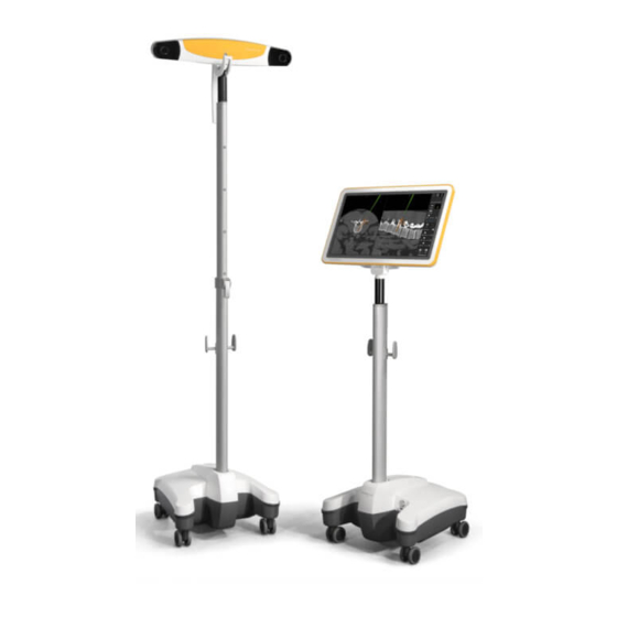
• Kick 2 Camera Cart • Kick 2 EM Tracking Unit The Kick 2 Monitor Cart must be used with either the Kick 2 Camera Cart or the Kick 2 EM Tracking Unit. All system components are suitable for continuous use during surgical procedures. - Page 24 WLAN Stick Edimax EW-7822ULC 18172 Kick 2 Navigation Camera Cart - Detachable Components Part Reference No. Camera Protection Cover 18174-01A Kick Vega Camera Telescopic Post Complete 18172-09 System and Technical User Guide Rev. 1.0 Kick 2 Navigation Station Ver. 1.1...
-
Page 25: System Setup
Move the equipment into the OR. Move the monitor into the desired position. Move the camera into the desired position. Lock all brakes on the Monitor Cart and Camera Cart. System and Technical User Guide Rev. 1.0 Kick 2 Navigation Station Ver. 1.1... - Page 26 Lock all brakes on the Monitor Cart. Unpack and set up the EM Tracking Unit. Move the monitor into the desired position. Connect all cables to the connection panel of the Monitor Cart. System and Technical User Guide Rev. 1.0 Kick 2 Navigation Station Ver. 1.1...
-
Page 27: Wlan Stick Assembly
How to Attach the WLAN Stick to the Monitor Cart Step Attach the WLAN Stick ① to the labeled port on the connection panel ②. ① ② System and Technical User Guide Rev. 1.0 Kick 2 Navigation Station Ver. 1.1... -
Page 28: Proper System Handling
System components are not suitable for use in the presence of flammable anesthetic mixtures containing air, oxygen or nitrous oxide. Tipping Hazard Warning Do not lean against the device. It may tip over. System and Technical User Guide Rev. 1.0 Kick 2 Navigation Station Ver. 1.1... -
Page 29: System Shutdown
When the LED turns off, unplug and secure all cables. Unplug the mains power cable from the Camera Cart and unplug and secure all cables. System and Technical User Guide Rev. 1.0 Kick 2 Navigation Station Ver. 1.1... - Page 30 System Shutdown System and Technical User Guide Rev. 1.0 Kick 2 Navigation Station Ver. 1.1...
-
Page 31: Monitor Cart
Monitor cable (not visible in image) ⑥ Monitor post with cable hooks ⑦ Power button Monitor Cart base, containing: ⑧ • Medical computer unit • Connection panel System and Technical User Guide Rev. 1.0 Kick 2 Navigation Station Ver. 1.1... - Page 32 For applications using life supporting or other critical signals, this information must be made available independent of the Kick 2 Navigation Station, for example by connecting the signal directly to a touch display (bypassing device).
- Page 33 Do not block or cover ventilation openings on the system, for example, with drapes. Air must be allowed to circulate through the vents to ensure proper operation and to avoid overheating. Do not place system near or over a radiator or heat register. System and Technical User Guide Rev. 1.0 Kick 2 Navigation Station Ver. 1.1...
-
Page 34: Air Filter Exchange
The Monitor Cart air filter must be exchanged annually. If you have a service contract, Brainlab automatically performs air filter exchange. If you do not have a service contract, contact Brainlab support to request a replacement air filter. Replacement Filters Only use replacement air filters that are provided by Brainlab. -
Page 35: Adjusting The Touchscreen
MONITOR CART Adjusting the Touchscreen Adjusting the Touchscreen Tilt The display can be tilted down by 10° (+2°) and up by 22° (+2°) relative to the vertical plane. System and Technical User Guide Rev. 1.0 Kick 2 Navigation Station Ver. 1.1... -
Page 36: Led Indications
Power On/Off LED Color Status Explanation Mains power is turned off. Safe to unplug system. Green Solid Mains power is on. Electronic components are booting or already on. System and Technical User Guide Rev. 1.0 Kick 2 Navigation Station Ver. 1.1... -
Page 37: Camera Cart
Cable hooks • Telescopic post ③ • Spiral camera cable (not visible) ④ Camera adjustment handle ⑤ Camera ⑥ Camera hinge ⑦ Camera handle ⑧ Clamping lever System and Technical User Guide Rev. 1.0 Kick 2 Navigation Station Ver. 1.1... - Page 38 In doubt, consult your local representative or the technical service department. Warning Do not lean against the device. It may tip over. System and Technical User Guide Rev. 1.0 Kick 2 Navigation Station Ver. 1.1...
- Page 39 ① ⑦ Figure 8 Component ① Camera release trigger ② Camera handle ③ Positioning laser ④ Illuminator filter ⑤ Lens ⑥ Camera adjustment handle ⑦ Laser trigger System and Technical User Guide Rev. 1.0 Kick 2 Navigation Station Ver. 1.1...
-
Page 40: Camera Cart Setup
IR-sensitive microscopes. If the camera’s infrared light interferes with other devices, reposition these devices and/or the camera so that the interference is resolved. System and Technical User Guide Rev. 1.0 Kick 2 Navigation Station Ver. 1.1... -
Page 41: Adjusting The Camera Cart
The positioning laser should also be monitored during the procedure. Reliance on data provided by an unclean or damaged positioning laser may lead to inaccurate conclusions. System and Technical User Guide Rev. 1.0 Kick 2 Navigation Station Ver. 1.1... - Page 42 Do not place any transparent or semi-transparent materials (such as drape foil or glass) between camera and tracked instruments as these can disturb the tracking functionality and accuracy of the camera. System and Technical User Guide Rev. 1.0 Kick 2 Navigation Station Ver. 1.1...
-
Page 43: Using The Camera
Every time the camera is turned on, it requires a warm-up time of two minutes. If the camera is stored at low temperatures, warm-up time may be longer. Compatible Devices Only use marker spheres and active Brainlab technology released for use with the camera. System and Technical User Guide Rev. 1.0 Kick 2 Navigation Station Ver. 1.1... -
Page 44: Leds And Acoustic Signals
When the position sensor is powered on, the power light flashes to indicate that the system is warming up. When the light stops flashing, the system is ready for use. System and Technical User Guide Rev. 1.0 Kick 2 Navigation Station Ver. 1.1... - Page 45 • Contact Brainlab support (even if navigation is still possi- ble). Acoustic Signals Camera emits two beeps when: • Reset is performed. • Power is applied to the Camera Cart. System and Technical User Guide Rev. 1.0 Kick 2 Navigation Station Ver. 1.1...
- Page 46 LEDs and Acoustic Signals System and Technical User Guide Rev. 1.0 Kick 2 Navigation Station Ver. 1.1...
-
Page 47: Em Tracking Unit
④ ① ⑤ Component ① EM Base Station ② EM Field Generator ③ EM Field Generator Positioning Arm ④ EM Power Supply ⑤ EM Power Data Cable System and Technical User Guide Rev. 1.0 Kick 2 Navigation Station Ver. 1.1... - Page 48 Power connection ② EM instrument LEDs ③ Power LED ④ EM instrument ports ⑤ Tool extension port (not used) ⑥ Navigation system port ⑦ EM Field Generator port System and Technical User Guide Rev. 1.0 Kick 2 Navigation Station Ver. 1.1...
- Page 49 EM TRACKING UNIT EM Power Supply (Class I) ③ ② ① ④ Figure 13 Component ① Mains power connector ② On/off switch ③ Power indicator ④ EM cable connector System and Technical User Guide Rev. 1.0 Kick 2 Navigation Station Ver. 1.1...
-
Page 50: Em Tracking Unit Setup
EM Field Generator fixation piece Mounting When attaching the EM Tracking Unit to operating table ensure that the mounting is designed to withstand the weight of the EM Tracking Unit. System and Technical User Guide Rev. 1.0 Kick 2 Navigation Station Ver. 1.1... - Page 51 Connect the power plug of the EM cable to power plug of the EM Power Supply. Connect mains power to Monitor Cart and the wall power outlet. Connect mains power to the EM Power Supply and wall power outlet. System and Technical User Guide Rev. 1.0 Kick 2 Navigation Station Ver. 1.1...
- Page 52 Hold the EM Base Station with one hand while connecting or disconnecting EM instruments with the other. In this way, no unintended movement of the EM Base Station on the OR table rail can occur. System and Technical User Guide Rev. 1.0 Kick 2 Navigation Station Ver. 1.1...
- Page 53 • Place the EM Field Generator within 10 m of another operating field generator as this might impact the tracking accuracy. Open connections by holding the connector. Never force connection or disconnection. Warning Please remove all metal jewelry including piercings before operating. System and Technical User Guide Rev. 1.0 Kick 2 Navigation Station Ver. 1.1...
- Page 54 Once the EM Tracking Unit is set up, if necessary, move the OR table carefully as it might pull on cables an move components. System and Technical User Guide Rev. 1.0 Kick 2 Navigation Station Ver. 1.1...
-
Page 55: Using The Em Tracking Unit
Do not block the ventilation openings of the EM Base Station. Component ① Left side of EM Base Station ② Air out ③ Back side of EM Base Station System and Technical User Guide Rev. 1.0 Kick 2 Navigation Station Ver. 1.1... - Page 56 Do not disconnect the EM Field Generator from the system while tracking. Disconnecting the EM Field Generator while in tracking mode may result in sparks being generated, and possible personal injury. System and Technical User Guide Rev. 1.0 Kick 2 Navigation Station Ver. 1.1...
- Page 57 Use an appropriate head rest ① for the patient in order to set the head on a level where the face of the EM Field Generator approximately covers the area of interest, including EM instruments. ① Figure 22 System and Technical User Guide Rev. 1.0 Kick 2 Navigation Station Ver. 1.1...
-
Page 58: Leds And Acoustic Signals
Acoustic Signals The EM Tracking Unit emits two beeps when: • Reset is performed. • Power is applied to system. • Connection is made to Brainlab software. System and Technical User Guide Rev. 1.0 Kick 2 Navigation Station Ver. 1.1... -
Page 59: Assembly, Transport And Storage
NOTE: The detailed descriptions of each step are provided in this section. How to Attach the Post ① ② ③ Figure 24 Step Push back the post fixation lever ③. System and Technical User Guide Rev. 1.0 Kick 2 Navigation Station Ver. 1.1... - Page 60 Run the monitor cable up the monitor post channel. Insert the cable clip into the corresponding notch in the post. How to Attach the Monitor ② ③ ① Figure 26 System and Technical User Guide Rev. 1.0 Kick 2 Navigation Station Ver. 1.1...
- Page 61 Attach the bottom section ③ of the Kick EM Holder . There should be enough friction be- tween the two parts to temporarily hold the lower end of the holder in place. ③ System and Technical User Guide Rev. 1.0 Kick 2 Navigation Station Ver. 1.1...
- Page 62 Assembling the Monitor Cart Step Secure the bottom section of the Kick EM Holder into position with the two thumbscrews ④ provided. ④ System and Technical User Guide Rev. 1.0 Kick 2 Navigation Station Ver. 1.1...
-
Page 63: Assembling The Camera Cart
ASSEMBLY, TRANSPORT AND STORAGE Assembling the Camera Cart General Information After assembly of Kick 2 Navigation Station carts verify that all mechanical connections are closed properly. Assembly Workflow Step Insert the telescopic camera post into the Camera Cart base. Clip spiral cable to the top of the telescopic camera post. - Page 64 Gently extend the spiral cable ① along the telescopic camera post, far enough that it nar- rows and can easily be inserted to the channel without applying force. Insert the cable clip into the corresponding notch ② in the post. System and Technical User Guide Rev. 1.0 Kick 2 Navigation Station Ver. 1.1...
- Page 65 Insert the camera cable into the corresponding port on the camera ②. Warning To prevent electrical shock only connect the spiral cable from the camera cart base to camera port. System and Technical User Guide Rev. 1.0 Kick 2 Navigation Station Ver. 1.1...
-
Page 66: Transport Outside The Hospital
Be extremely careful not to clamp fingers or other body parts in the moving parts of the transport cases. Joints that may clamp body parts include, but are not limited to: System and Technical User Guide Rev. 1.0 Kick 2 Navigation Station Ver. 1.1... - Page 67 • Pack the system components in the transport cases only as described in this user guide. Make sure that transport cases are secured when transporting (e.g., by car). System and Technical User Guide Rev. 1.0 Kick 2 Navigation Station Ver. 1.1...
-
Page 68: Disassembling And Transporting The Monitor Cart
Cover the metal connector of the monitor cable with the cloth bag ② provided. With the top foam insert flipped up, insert the Monitor Cart base into the case. System and Technical User Guide Rev. 1.0 Kick 2 Navigation Station Ver. 1.1... - Page 69 Place the post into the foam insert slot ① of the shoulder transport bag. NOTE: The second slot is intended for the Kick 2 Camera Cart post. System and Technical User Guide Rev. 1.0 Kick 2 Navigation Station Ver. 1.1...
- Page 70 Disassembling and Transporting the Monitor Cart Step Fully close the case zipper. System and Technical User Guide Rev. 1.0 Kick 2 Navigation Station Ver. 1.1...
-
Page 71: Disassembling The Camera Cart
Cover the metal connector of the spiral cable with the cloth bag ① provided. Place foam insert on top of the base, then insert camera ③. Fully close the zipper of the transport case. System and Technical User Guide Rev. 1.0 Kick 2 Navigation Station Ver. 1.1... -
Page 72: Parking And Storage
Parking and Storage General Information Each wheel on the Kick 2 Navigation Station has an individual foot brake so that it can be easily transported and securely parked. Fully lock all brakes when the cart is stored, parked or in operation. -
Page 73: Transporting The Monitor Cart Inside The Hospital
How to Attach the Monitor Protection Cover Step Shut down, turn off and unplug the system. After the monitor has cooled down, clean the touchscreen. Pull the monitor protection cover over the monitor. System and Technical User Guide Rev. 1.0 Kick 2 Navigation Station Ver. 1.1... - Page 74 Transporting the Monitor Cart Inside the Hospital Step Close the Velcro straps, ensuring that the cover sits properly on the monitor. System and Technical User Guide Rev. 1.0 Kick 2 Navigation Station Ver. 1.1...
-
Page 75: Transporting The Camera Cart Inside The Hospital
NOTE: The camera must be switched off for at least five minutes before it is covered. NOTE: The camera must not be protected or covered with methods not approved by Brainlab. Obstructing the normal air flow around the camera (e.g., by draping or bagging the camera) will affect the camera operational environment, possibly beyond its recommended thresholds. - Page 76 Transporting the Camera Cart Inside the Hospital Warning The Camera Cart may tilt if it is not put in the defined transport position. System and Technical User Guide Rev. 1.0 Kick 2 Navigation Station Ver. 1.1...
-
Page 77: Transporting The Em Tracking Unit
Unfasten the hook and loop straps on the Monitor Cart and remove the EM power sup- ply. Place the power supply in the designated position in the transport case ⑦. System and Technical User Guide Rev. 1.0 Kick 2 Navigation Station Ver. 1.1... - Page 78 Store the EM Field Generator Positioning Arm ⑨ in the top layer of the transport case. Put the unsterile instruments into the unsterile instrument case ⑪. Place the unsterile instrument case into the transport case ⑩. System and Technical User Guide Rev. 1.0 Kick 2 Navigation Station Ver. 1.1...
-
Page 79: Cleaning
No Liquids Ensure that liquids do not enter the system, as this could damage the component and/orthe electronics. System components are not protected against the ingress of liquids. System and Technical User Guide Rev. 1.0 Kick 2 Navigation Station Ver. 1.1... -
Page 80: Cleaning The Monitor Cart
NOTE: If a soiled cover cannot be sufficiently cleaned using the above steps, exchange the cover for a new one. NOTE: Do not wash, soak, iron or sterilize protection cover. System and Technical User Guide Rev. 1.0 Kick 2 Navigation Station Ver. 1.1... -
Page 81: Cleaning The Camera Cart
Allow the protection cover to fully dry before attaching it to the camera. NOTE: After drying, surface disinfectants may leave stains. System and Technical User Guide Rev. 1.0 Kick 2 Navigation Station Ver. 1.1... - Page 82 Continue cleaning the remainder of the camera. Take care not to wipe debris from the camera case onto the illuminators and sensors. Avoid prolonged contact between the wipes and the camera. System and Technical User Guide Rev. 1.0 Kick 2 Navigation Station Ver. 1.1...
-
Page 83: Cleaning The Em Tracking Unit
How to Clean EM Tracking Unit Step Unplug all cables from the EM Tracking Unit. Clean all housing surfaces using a surface disinfectant (see list of Brainlab approved dis- infectants). Follow disinfectant manufacturer's recommendations. Carefully clean interfaces, ensuring that no liquids enter the system. -
Page 84: Cleaning Transport Cases
Allow the transport cases to fully dry before inserting the system. NOTE: After drying, surface disinfectants may leave stains. System and Technical User Guide Rev. 1.0 Kick 2 Navigation Station Ver. 1.1... -
Page 85: Electrical Safety
F-Type Applied Part complying with the specified requirements of this stand- Type BF ard to provide a higher degree of protection against electric shock than that provided by Type B Applied Parts. System and Technical User Guide Rev. 1.0 Kick 2 Navigation Station Ver. 1.1... -
Page 86: Recurrent Test Requirements
If items of ME EQUIPMENT that are combined into an ME SYSTEM by functional connections cannot be tested separately for technical reasons, test the complete ME SYSTEM. In addition, Brainlab support or authorized partners shall regularly clean air intake filters and exchange the battery when necessary. -
Page 87: Test Steps
Refer to the corresponding manufacturer’s instructions for the measuring device you are using. NOTE: If you are unsure whether your measuring device is suitable, contact Brainlab support. Testing Precautions ME SYSTEM test steps must be performed as described below. The described test only covers the Brainlab Kick 2 Navigation Station equipment and not connected equipment. - Page 88 Test each piece of equipment of the ME SYSTEM individually, according to steps 1-4 for ME EQUIPMENT. Report and evaluate these results. Touch current Document results Evaluate results Check and prepare for normal use System and Technical User Guide Rev. 1.0 Kick 2 Navigation Station Ver. 1.1...
-
Page 89: Safety Inspection Form - Recurrent Tests
Check and prepare service. for normal use Remove all devices that have been connected (e.g., measurement lines). System and Technical User Guide Rev. 1.0 Kick 2 Navigation Station Ver. 1.1... - Page 90 Inspection Personnel Only trained and skilled hospital technicians are allowed to perform electrical safety tests. • If a suitably qualified person is not available at the customer site, Brainlab support will perform this inspection for a set fee. • If you require a Brainlab support specialist, contact Brainlab support.
-
Page 91: Performing Tests
Connect the measurement tip of your measuring device with the conductive parts shown in the table below and measure the resistance. If a test does not pass, device must be repaired by Brainlab support. After repair, repeat the entire electrical safety test from the beginning. -
Page 92: Equipment Leakage Current
Equipment Leakage Current Measurement Points (Monitor Cart) Point Tested Measured Value Test Passed? Potential equalization port Microscope fixation screw Screw on the back of the monitor (any screw under cover) Post fixation System and Technical User Guide Rev. 1.0 Kick 2 Navigation Station Ver. 1.1... - Page 93 The following equipment leakage test points are defined for the EM Tracking Unit in combination with the Monitor Cart. Point Tested Measured Value Test Passed? EM Field Generator at EM Base Station Power connector at EM Base Station System and Technical User Guide Rev. 1.0 Kick 2 Navigation Station Ver. 1.1...
- Page 94 Equipment Leakage Current Point Tested Measured Value Test Passed? Mounting suspension at EM Base Station EM instrument port at EM Base Station System and Technical User Guide Rev. 1.0 Kick 2 Navigation Station Ver. 1.1...
-
Page 95: Applied Part Leakage Current (Type Bf) (For Optional Em Tracking Unit)
For example: Figure 38 Measurement Point Point Tested Measured Value Test Passed? Adapter plug on EM con- necting unit (test the four ports) System and Technical User Guide Rev. 1.0 Kick 2 Navigation Station Ver. 1.1... -
Page 96: Electrical Safety Test - Medical Electrical System
Inspection Personnel Only trained and skilled hospital technicians are allowed to perform electrical safety tests. • If a suitably qualified person is not available at the customer site, Brainlab support will perform this inspection for a set fee. • If you require a Brainlab support specialist, contact Brainlab support. -
Page 97: Testing Medical Electrical Systems
• Keep it as a record of the inspection. Required Test Steps Step Perform visual inspection. Check touch current. Perform functional test. Report and evaluate results. Check and prepare system for normal use. System and Technical User Guide Rev. 1.0 Kick 2 Navigation Station Ver. 1.1... -
Page 98: Safety Inspection Form - Medical Electrical Systems (Monitor Cart)
Test Step Normal Condi- Single Fault Passed? tion Condition Touch current Serial number of measuring device: ________________________ Calibration valid through (date): ________________________ Test performed (date): _________________by: __________________________________ System and Technical User Guide Rev. 1.0 Kick 2 Navigation Station Ver. 1.1... -
Page 99: Touch Current For Medical Electrical Systems
Measuring Test Points (Camera Cart) Point Tested Measured Value Test Passed? Network port, connection panel Measuring Test Points (EM Tracking Unit) Point Tested Measured Value Test Passed? EM Base Station System and Technical User Guide Rev. 1.0 Kick 2 Navigation Station Ver. 1.1... - Page 100 Touch Current for Medical Electrical Systems System and Technical User Guide Rev. 1.0 Kick 2 Navigation Station Ver. 1.1...
-
Page 101: Compliances And Specifications
COMPLIANCES AND SPECIFICATIONS COMPLIANCES AND SPECIFICATIONS Electrical Standards Certificates and Approvals Certificate/Approval IEC 60601-1 Certificates ANSI/AAMI ES60601-1 System and Technical User Guide Rev. 1.0 Kick 2 Navigation Station Ver. 1.1... -
Page 102: Weight And Dimensions
1463 mm Camera Cart Specification Value Weight including safe working load 19 kg Width 591 mm Length 500 mm Minimum height 1450 mm Max. Height 2350 mm System and Technical User Guide Rev. 1.0 Kick 2 Navigation Station Ver. 1.1... - Page 103 200 mm Length 100 mm Weight 2.5 kg EM Field Generator Figure 40 Specification Value Height 200 mm Width 200 mm Length 71 mm Weight 2.8 kg System and Technical User Guide Rev. 1.0 Kick 2 Navigation Station Ver. 1.1...
- Page 104 Weight and Dimensions EM Field Generator Arm Figure 41 Specification Value Height 748 mm Width 110 mm Length 88 mm Weight 4 kg System and Technical User Guide Rev. 1.0 Kick 2 Navigation Station Ver. 1.1...
-
Page 105: Technical Specifications
1.6 A @ 100 VAC Power consumption 0.8 A @ 240 Vac • 1 x Ethernet Supported I/O • 1 x Power in • 1 x Potential Equalization port System and Technical User Guide Rev. 1.0 Kick 2 Navigation Station Ver. 1.1... - Page 106 ② IEEE Std. C95.6-2002, limb ③ IEEE Std. C95.6-2002, head & torso (controlled environment) ④ Planar FG (Field Generator) Field ⑤ EM Field Generator Magnetic Field Plots System and Technical User Guide Rev. 1.0 Kick 2 Navigation Station Ver. 1.1...
- Page 107 Human Exposure to Electromagnetic Fields, 0-3 kHz.”) NOTE: Information from text and graphic obtained from "Brainlab EM Aurora V3.1 Basestation User Guide (Revision 1 from October 2019)". System and Technical User Guide Rev. 1.0 Kick 2 Navigation Station Ver. 1.1...
-
Page 108: Environmental Requirements
For the malware protection of the platform, see the information under Software Environment in this user guide. • Ensure that prescribed maintenance is done as required, including installation of security patches. • Security awareness training of the users. System and Technical User Guide Rev. 1.0 Kick 2 Navigation Station Ver. 1.1... - Page 109 Using the device outside of the intended operating environment may lead to cybersecurity incidents that may affect safety and effectiveness of the device Related Links Software Environment on page 15 System and Technical User Guide Rev. 1.0 Kick 2 Navigation Station Ver. 1.1...
-
Page 110: Compliances
If such use is necessary, this equipment and the other equipment should be observed to verify that they are operating normally. System and Technical User Guide Rev. 1.0 Kick 2 Navigation Station Ver. 1.1... -
Page 111: Electromagnetic Immunity, Kick 2 Navigation Station System
TETRA 400 18 Hz GMRS 460, 430 - 470 ± 5 deviation FRS 460 1 kHz sine Pulse modula- LTE Band 13, tion 704 - 787 217 Hz System and Technical User Guide Rev. 1.0 Kick 2 Navigation Station Ver. 1.1... - Page 112 150 kHz to Recommended separation distance: 61000-4-6 80 MHz d = 1.17√P d = 1.17√P 80 MHz to 800 MHz d = 2.3√P 800 MHz to 2.5 GHz System and Technical User Guide Rev. 1.0 Kick 2 Navigation Station Ver. 1.1...
- Page 113 RF transmitters, an electromagnetic site survey should be considered. If the measured field strength in the location in which the Kick 2 Navigation Station system is used exceeds the applicable RF compliance level above, the Kick 2 Navigation Station system should be ob- served to verify normal operation.
-
Page 114: Rf Communications Equipment
Warning Portable RF communications equipment (including peripherals like antenna cables and external antennas) should not be used closer than 30 cm from any part of the Kick 2 Navigation Station including cables specified by Brainlab. Otherwise, degradation of the performance could result. -
Page 115: Tested Cables
Cable Specifications for Optical Tracking Kick 2 Navigation Station system cables that have been tested for emission and immunity conformity: Cable... - Page 116 Length (xx) customer specific Included in External Access Ethernet interface See note Point Cable Specifications for EM Tracking Kick 2 Navigation Station system cables that have been tested for emission and immunity conformity: Cable Type Note 16900-41 for USA, Canada...
- Page 117 Type Note Not included in device configu- TTL DP-AOC-20M DisplayPort ration; length customer-specif- TTL DP-AAOC-xxM Part of microscope integration/ See note footswitch/USB stick/included in External Access Point System and Technical User Guide Rev. 1.0 Kick 2 Navigation Station Ver. 1.1...
-
Page 118: Supported Resolutions
8Bit RGB DVI-I DVI-D 640x480@72Hz 640x480 Extron-26-651-35 max. 5m 8Bit RGB DVI-I DVI-D 640x480@60Hz 640x480 Extron-26-651-35 max. 5m 8Bit RGB DVI-I DVI-D 720x480@60Hz 720x480 Extron-26-651-35 max. 5m System and Technical User Guide Rev. 1.0 Kick 2 Navigation Station Ver. 1.1... - Page 119 720p50 1280x720 R2GR-1000-GN- 75 Ohm Sommer cable max. 10Bit YUV 4:2:2 480i60 720x480 R2GR-1000-GN- 75 Ohm Sommer cable 480i59,9 max. 10Bit YUV 4:2:2 720x480 R2GR-1000-GN- 75 Ohm System and Technical User Guide Rev. 1.0 Kick 2 Navigation Station Ver. 1.1...
- Page 120 7.5 m DVI-I Composite 625i 720x576 Brainlab 17752-08 7.5 m Supported Output Resolutions The table below specifies the supported output resolutions for display output available on Kick 2 Navigation Station. Displays Color Coding Connector Signal Type Refresh Resolution Required Cable...
-
Page 121: Hospital Network
• Minimum: ≤ 50 ms • Recommended: ≤ 25 ms Latency • Optimum: ≤ 2 ms Safety See Software Environment. Related Links Environmental Requirements on page 108 System and Technical User Guide Rev. 1.0 Kick 2 Navigation Station Ver. 1.1... - Page 122 Hospital Network System and Technical User Guide Rev. 1.0 Kick 2 Navigation Station Ver. 1.1...
-
Page 123: 10 Maintenance
The system should be maintained and inspected once a year to ensure functionality, EMC compliance and safety. Do not carry out inspections while Kick 2 Navigation Station is being used for patient treatment. Before Using the System If the system has not been used for an extended period of time, verify that everything operates normally before beginning patient treatment. -
Page 124: Malfunctions And Return Instructions
• System emits smoke. • The LEDs indicate an error. • Cybersecurity incident. If a error message appears on the touchscreens or if the error LEDs are lit, contact Brainlab support. Do not use the system. How to Respond to Damage or Failure Step Turn off system. -
Page 125: Return Instructions
Complete and return the form that was faxed to you or that accompanied replacement part. Securely tape the box shut. Ship the defective component to relevant return address or follow instructions given by Brainlab support. System and Technical User Guide Rev. 1.0 Kick 2 Navigation Station Ver. 1.1... - Page 126 Return Instructions System and Technical User Guide Rev. 1.0 Kick 2 Navigation Station Ver. 1.1...
-
Page 127: 11 Appendix
APPENDIX 11 APPENDIX 11.1 Firewall Settings Inbound Rules NOTE: This information available in machine readable format from Brainlab on request. System and Technical User Guide Rev. 1.0 Kick 2 Navigation Station Ver. 1.1... - Page 128 Firewall Settings System and Technical User Guide Rev. 1.0 Kick 2 Navigation Station Ver. 1.1...
- Page 129 APPENDIX System and Technical User Guide Rev. 1.0 Kick 2 Navigation Station Ver. 1.1...
- Page 130 Firewall Settings System and Technical User Guide Rev. 1.0 Kick 2 Navigation Station Ver. 1.1...
- Page 131 APPENDIX System and Technical User Guide Rev. 1.0 Kick 2 Navigation Station Ver. 1.1...
- Page 132 Firewall Settings System and Technical User Guide Rev. 1.0 Kick 2 Navigation Station Ver. 1.1...
-
Page 133: Index
51 set up.................50,54 transport cases............... 50 recurrent test ventilation................55 guidelines................87 emergency access..............17 requirements................86 returning equipment addresses................125 RF communications equipment..........114 field generator................50 System and Technical User Guide Rev. 1.0 Kick 2 Navigation Station Ver. 1.1... - Page 134 Camera Cart................37 system size................102 system ventilation..............33,55 technical specifications camera cart................105 EM tracking unit..............106 monitor cart................105 transport procedure..............66 ventilation................33,55 waste electrical and electronic equipment (WEEE)......8 System and Technical User Guide Rev. 1.0 Kick 2 Navigation Station Ver. 1.1...
- Page 136 Art-No. 60921-06EN * 60921-06EN*...
Need help?
Do you have a question about the KICK 2 and is the answer not in the manual?
Questions and answers