Brainlab KICK 2 System And Technical User Manual
Hide thumbs
Also See for KICK 2:
- System and technical user manual (94 pages) ,
- System and technical user manual (136 pages)

Related Manuals for Brainlab KICK 2


Summary of Contents for Brainlab KICK 2
- Page 1 KICK 2 NAVIGATION STATION System and Technical User Guide Revision 1.3 Copyright 2018, Brainlab AG Germany. All rights reserved.
-
Page 3: Table Of Contents
3.2.2 Moving Parts ............................32 3.3 Turning On Kick 2 ..........................33 3.4 Turning Off Kick 2 ..........................34 3.5 Sterile Use ............................35 3.5.1 Sterile Kick Monitor Drape.........................35 3.6 System Connections ........................37 System and Technical User Guide Rev. 1.3 Kick 2 Navigation Station... - Page 4 6.4 Electrical Safety Test – Medical Electrical System ..............74 6.4.1 Overview ............................74 6.4.2 Testing Medical Electrical Systems....................75 6.4.3 Safety Inspection Form – Medical Electrical Systems...............76 6.4.4 Touch Current for Medical Electrical Systems...................78 System and Technical User Guide Rev. 1.3 Kick 2 Navigation Station...
- Page 5 8.1.3 Annual Inspection by Brainlab ......................95 8.2 Air Filter Exchange ...........................96 8.3 Malfunctions and Return Instructions ..................97 8.3.1 Return Instructions ...........................98 9 TROUBLESHOOTING ......................99 9.1 Troubleshooting the Kick 2 ......................99 System and Technical User Guide Rev. 1.3 Kick 2 Navigation Station...
- Page 6 TABLE OF CONTENTS System and Technical User Guide Rev. 1.3 Kick 2 Navigation Station...
-
Page 7: General Information
Careful functional testing and inspection of the Kick 2 before use is the best method for determining the end of lifetime. The end of lifetime is normally determined by wear and tear damage due to use. As part of preventive service, follow the maintenance instructions. -
Page 8: Legal Information
Council Directive 93/42/EEC (the MDD). • According to the principles set out in the MDD, Kick 2 is a Class IIb product. NOTE: The validity of the CE label can only be confirmed for products manufactured by Brainlab. - Page 9 The WLAN module included in this product cannot be accessed by end users. The FCC ID of the WLAN module is listed on the WLAN label attached to the Kick 2. Contact Brainlab support for any related questions.
-
Page 10: Symbols
Cautions are indicated by circular caution symbols. They contain important information regarding potential device malfunctions, device failure, damage to device or damage to property. Notes NOTE: Notes are formatted in italic type and indicate additional useful hints. System and Technical User Guide Rev. 1.3 Kick 2 Navigation Station... -
Page 11: Hardware Symbols
Storage conditions for air pressure: The specified air pressure range is shown on each label. Radio device Class 2 wireless LAN Serial number Article number System and Technical User Guide Rev. 1.3 Kick 2 Navigation Station... - Page 12 Unique device identification Danger of tilting: Do not move when brakes are locked or if device is blocked by obstacles. Power switch to power on the device. Consult accompanying documentation System and Technical User Guide Rev. 1.3 Kick 2 Navigation Station...
-
Page 13: Intended Use
Intended Use Intended System Use Kick 2 is intended for use as a mobile computing platform hosting one or more software applications. Kick 2 facilitates the display and exchange of, as well as the interaction with data. Kick 2 also offers interaction with external/additional devices or components within the defined performance specification while used in the intended use environment. - Page 14 Before patient treatment, review the plausibility of all information input to and output from the system. Responsibility This system solely provides assistance to the surgeon and does not substitute or replace the surgeon’s experience and/or responsibility during its use. System and Technical User Guide Rev. 1.3 Kick 2 Navigation Station...
-
Page 15: Compatibility With Medical Devices
Compatible Brainlab Medical Components Kick 2 is compatible with Kick Monitor Drape. Compatible Optional Accessories Kick 2 is compatible with an optional Converter Kit DVI to S-Video. Other Brainlab Instruments Additional instrumentation may become available after release of this manual. Contact Brainlab support if you have any questions regarding instrument compatibility with Brainlab software. -
Page 16: Training
Training Training Brainlab Training Before using the system, Brainlab recommends that all users should participate in a training program held by a Brainlab representative to ensure safe and appropriate use. Supervised Support Before using the system for surgical procedures where computer-aided navigation is considered critical, perform a sufficient number of complete procedures together with a Brainlab representative. -
Page 17: Documentation
GENERAL INFORMATION Documentation Terminology Unless otherwise specified, the Kick 2 Navigation Station shall be referred to as “Kick 2” in this user guide. Intended Audience This user guide is intended for surgeons and hospital staff. Reading User Guides This guide describes complex medical software or medical devices that must be used with care. - Page 18 Documentation System and Technical User Guide Rev. 1.3 Kick 2 Navigation Station...
-
Page 19: Kick 2 Overview
Overview Kick 2 Kick 2 is a mobile Medical Electrical (ME) device. It consists of a Monitor Cart, including a medical computer unit (MCU) and a base display including touchscreen, with a suitable tracking unit. Moreover, it offers interfaces necessary for exchange of data with additional devices or components. -
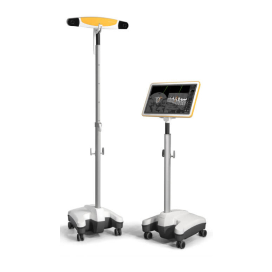
Page 20: Monitor Cart Components
Touchscreen ⑤ Monitor cable (not visible in image) ⑥ Monitor post with cable hooks ⑦ Power button Monitor Cart base, containing: ⑧ • Medical computer unit • Connection panel System and Technical User Guide Rev. 1.3 Kick 2 Navigation Station... - Page 21 USB 2.0 ⑧ USB 3.0 ⑨ Microscope/Video Out Tracking Unit The Kick 2 (article number 18170) can be used with either of the following components: Component Article Number Kick 2 Spectra Camera Cart 18178 Kick 2 Vega Camera Cart 18172...
- Page 22 Monitor Cart Components Component Article Number Adapter (USB to Ethernet) (optional) 18177 System and Technical User Guide Rev. 1.3 Kick 2 Navigation Station...
-
Page 23: Monitor
• Position monitor so as to not interfere with surgery or movement of the OR staff. Protecting Touchscreen Surface Do not use a damaged touchscreen. Always check the touchscreen condition before beginning a procedure. Do not use sharp tools on the touchscreen. System and Technical User Guide Rev. 1.3 Kick 2 Navigation Station... - Page 24 Monitor Proper Cart Use Do not attach or hang anything on the Monitor Cart unless specified by Brainlab and do not lean on the Monitor Cart. Doing so may cause the cart to tip over. System and Technical User Guide Rev. 1.3 Kick 2 Navigation Station...
-
Page 25: Range Of Motion
The monitor can be rotated via the monitor hinge on the horizontal plane: • 22° backward • 10° forward The viewing angle of the monitor is at least 80° in all four directions. System and Technical User Guide Rev. 1.3 Kick 2 Navigation Station... -
Page 26: Monitor Cart Ventilation
Do not place system near or over a radiator or heat register or in direct sunlight. System and Technical User Guide Rev. 1.3 Kick 2 Navigation Station... -
Page 27: Using Kick 2
All system components are suitable for continuous use during surgical procedures. Interference Kick 2 does not have an essential performance as defined by IEC 60601-1. However, the influence of electromagnetic disturbances might lower performance. Strong electromagnetic interferences may affect the touch technology and the loss of wireless network connection. - Page 28 Attach the mains power cable to the tracking unit ① and plug into wall outlet. Connect the Ethernet cable to the network port ② on the tracking unit. The system is now ready to be turned on. System and Technical User Guide Rev. 1.3 Kick 2 Navigation Station...
-
Page 29: Or Setup
The setup example below is only a suggestion. For detailed setup descriptions, see the relevant Software User Guide. Kick 2 Setup Example Figure 6 The following example shows the Kick 2 with a tracking unit (in this example, Kick 2 Spectra Camera Cart). System and Technical User Guide Rev. 1.3 Kick 2 Navigation Station... -
Page 30: Proper System Handling
Do not touch the electrical contacts of plugs. Appropriate Positioning To avoid damage to the Kick 2, other equipment or people, always move, park and operate in the respective appropriate position. The Kick 2 may only be used on level surfaces. - Page 31 Kick 2 or shielding the location. Portable and mobile radio frequency communication may affect the equipment. Other OR equipment may cause an interference with Kick 2, even if it is CISPR emission compliant. Restrictions to Environment...
-
Page 32: Moving Parts
Be extremely careful not to clamp fingers or other body parts when positioning the monitor. Monitor Cart joints that may clamp body parts include, but are not limited to: Post fixation lever Monitor handle (during assembly) Wheels System and Technical User Guide Rev. 1.3 Kick 2 Navigation Station... -
Page 33: Turning On Kick 2
Turning On Kick 2 Power Supply Operate Kick 2 using the power source indicated on type plate. If you are unsure of type of power available, consult Brainlab-authorized support or your local power company. Using the wrong power source could seriously damage the device. -
Page 34: Turning Off Kick 2
How to Reset Step To reset Kick 2 (if it has frozen or has not completely shut down) press the power button for four seconds, until it turns off. Wait 10 seconds, then press the power button again to restart. -
Page 35: Sterile Use
Sterile Kick Monitor Drape General Information Kick 2 is unsterile. The Monitor Cart may be used within the patient environment when using the Kick Monitor Drape provided by Brainlab. The drape allows you to intraoperatively access all software functions and position monitor during surgery without compromising the sterile field. - Page 36 Peel the adhesive liner off the adhesive strips ④ on the lower part of the drape and attach them to the monitor post. System and Technical User Guide Rev. 1.3 Kick 2 Navigation Station...
-
Page 37: System Connections
3.0 ports on the front of the cart base. Otherwise safety and effectiveness of the equipment cannot be guaranteed. Restrictions Connecting Equipment to Panels Warning Only connect equipment to the Kick 2 that is specified by Brainlab or for which Brainlab has declared compatibility. Warning Additional equipment connected to medical electrical equipment must comply with the respective IEC or ISO standards (e.g., IEC 60950 for data processing equipment and IEC... - Page 38 Display of 3D Content Kick 2 delivers a progressive single stream signal with a resolution of 1920 x 1080 at 60 Hz. To correctly display 3D content created by some Brainlab software, an external display must support 3D line-by-line technology.
-
Page 39: Back Panel Connections
For detailed information on microscope integration see the corresponding Instrument User Guide. Video out may also be used for the DVI connection. Video Out NOTE: Brainlab does not provide this cable. System and Technical User Guide Rev. 1.3 Kick 2 Navigation Station... -
Page 40: Tracking Unit
How to Connect a Tracking Unit Step Plug the Ethernet cable to the tracking unit port on the Monitor Cart. Connect the Ethernet cable to the tracking unit. Power devices on. System and Technical User Guide Rev. 1.3 Kick 2 Navigation Station... -
Page 41: Optional Components
① is on the lower side (closest to the base) and is pointing to- ward the back of the cart. Connect the cable to a USB 3.0 port on the connection panel. Press eject button to open the tray and insert/remove DVD. System and Technical User Guide Rev. 1.3 Kick 2 Navigation Station... - Page 42 Connect Ethernet cable to the Ethernet port of the adapter ①. NOTE: Do not use the USB-to-Ethernet adapter to connect a tracking unit. Always connect the tracking unit directly to the Ethernet port labeled Tracking Unit. System and Technical User Guide Rev. 1.3 Kick 2 Navigation Station...
-
Page 43: Cabling
Do not tug on or pull cables. Risk of electrical shock: Do not touch cable plugs when Kick 2 is turned on. Ensure that tracking unit cable is not used to connect any device other than the Monitor Cart and tracking unit. - Page 44 To disconnect the cable, press the yellow button to release it from the port (see arrow above). Always remove the mains power cable from the wall outlet first, before unplugging the cable from the system. System and Technical User Guide Rev. 1.3 Kick 2 Navigation Station...
-
Page 45: Cable Storage
The following cables typically remain connected to the cart: • Mains power cable • Tracking unit cable • Hospital network cable • Potential equalization cable Carefully bundle the cables together and hang them from the cable hooks. System and Technical User Guide Rev. 1.3 Kick 2 Navigation Station... - Page 46 Cable Storage System and Technical User Guide Rev. 1.3 Kick 2 Navigation Station...
-
Page 47: Assembly, Transport And Storage
Shut down, turn off and unplug the system. After the monitor has cooled down, pull the monitor protection cover over the monitor. Close the Velcro straps, ensuring that the cover sits properly on the monitor. System and Technical User Guide Rev. 1.3 Kick 2 Navigation Station... -
Page 48: Transport Outside Of The Hospital
(e.g., not by pregnant women). Transport Cases Figure 16 Three transport cases are needed for transporting the Kick 2 outside of the hospital: • Transport case for the monitor • Transport case for the Monitor Cart base • Shoulder bag for cart post and cables In order to pack the system into the cases, it must be disassembled. - Page 49 Make sure that transport cases are secured when transporting (e.g., by car). Post-Transport After transporting, wait until the system has adjusted to room temperature before operating. Related Links 7.3 System Specifications on page 81 System and Technical User Guide Rev. 1.3 Kick 2 Navigation Station...
-
Page 50: Assembling The Kick 2
Push back the post fixation lever ③. While holding monitor cable out of the way ②, slide bottom end of the monitor post into the Monitor Cart base ①. Close post fixation lever securely. System and Technical User Guide Rev. 1.3 Kick 2 Navigation Station... - Page 51 The release trigger clicks when the monitor is securely attached. Open the flap on the back of the monitor ②. Attach monitor cable to the monitor and secure latching pins ③. System and Technical User Guide Rev. 1.3 Kick 2 Navigation Station...
- Page 52 Assembling the Kick 2 Step Once attached, close the flap on the back of the monitor ②. System and Technical User Guide Rev. 1.3 Kick 2 Navigation Station...
-
Page 53: Disassembling And Transporting The Kick 2
Cover the metal connector of the monitor cable with the cloth bag provided. Fully close the zipper of the transport case. How to Transport the Monitor Cart Base ① ② Figure 20 System and Technical User Guide Rev. 1.3 Kick 2 Navigation Station... - Page 54 ②. Attach the Velcro strap of the monitor case to the corresponding handle on the Monitor Cart base case. How to Transport the Monitor Cart Post ① Figure 22 System and Technical User Guide Rev. 1.3 Kick 2 Navigation Station...
- Page 55 Step Place the post into the foam insert slot ① of the shoulder transport bag. NOTE: The second slot is intended for the Kick 2 Camera Cart post. Fully close the case zipper. System and Technical User Guide Rev. 1.3 Kick 2 Navigation Station...
-
Page 56: Proper Transport Inside The Hospital
Use the monitor handle ① to transport the Monitor Cart. Warning Never move the cart on a surface with >10° tilt as transport speed increases on inclined surfaces, increasing the risk of the cart tipping over System and Technical User Guide Rev. 1.3 Kick 2 Navigation Station... - Page 57 Pull the Monitor Cart to the point of depth variation, then carefully tilt the cart slightly and move one wheel at a time over the step. NOTE: Do not lift the entire cart. Be careful not to tilt the cart so much that it tips over. System and Technical User Guide Rev. 1.3 Kick 2 Navigation Station...
-
Page 58: Parking And Storage
To lock, push the brake pedal ③ down with your foot until it snaps into locked position ①. To unlock, push brake pedal ③ up with your foot until it snaps into unlocked position ②. System and Technical User Guide Rev. 1.3 Kick 2 Navigation Station... -
Page 59: Parking Kick 2
When the system is not in use, always keep the cart in the secure transport and parking position. Warning Never park the cart or take the cart out of transport position on a surface with >10° tilt. System and Technical User Guide Rev. 1.3 Kick 2 Navigation Station... -
Page 60: Storage
Storage 4.4.3 Storage Safe Storage When storing the system, always use the protection cover. Related Links 7.2 Environmental Requirements on page 80 System and Technical User Guide Rev. 1.3 Kick 2 Navigation Station... -
Page 61: Long Term Storage
Before using equipment that has been stored for six months or longer: • Clean the equipment. • Perform a recurrent test to verify safety and effectiveness of equipment (offered by Brainlab). • Start system and verify correct function before using it for surgery. - Page 62 Long Term Storage System and Technical User Guide Rev. 1.3 Kick 2 Navigation Station...
-
Page 63: Cleaning
No Liquids Ensure that liquids do not enter the Kick 2 components, as this could damage the component and/or the electronics. System components are not protected against the ingress of liquids. Use only a moist cloth for cleaning. Other methods could allow liquids to enter the system and cause damage. - Page 64 Clean all housing surfaces using a surface disinfectant, following the disinfectant manu- facturer’s recommendations. Carefully clean the interfaces, ensuring that no liquids enter the system. Clean the touchscreen with a lint-free wipe using a streak-free surface disinfectant. System and Technical User Guide Rev. 1.3 Kick 2 Navigation Station...
-
Page 65: Cleaning The Monitor Protection Cover
NOTE: If a soiled cover cannot be sufficiently cleaned using the above steps, exchange the cover for a new one. Do not wash, soak, iron or sterilize protection cover. System and Technical User Guide Rev. 1.3 Kick 2 Navigation Station... -
Page 66: Cleaning Transport Cases
Clean and disinfect only the outside surfaces of the transport cases. Do not clean or disin- fect surfaces on the inside of the cases. Allow the transport cases to fully dry before inserting the system. NOTE: After drying, surface disinfectants may leave stains. System and Technical User Guide Rev. 1.3 Kick 2 Navigation Station... -
Page 67: Electrical Safety
PE (protective earth). Safety Requirements To avoid the risk of electrical shock, the Monitor Cart must only be connected to a mains power supply with protective earth. System and Technical User Guide Rev. 1.3 Kick 2 Navigation Station... -
Page 68: Recurrent Test Requirements
• Informs Brainlab immediately in writing if the equipment is deemed unsafe. Inspections by Brainlab Support • If a suitably qualified person is not available at the customer site, Brainlab support will perform this inspection for a set fee. • If you require a Brainlab support specialist, contact Brainlab support. -
Page 69: Test Steps
If a test does not pass, device must be repaired by Brainlab support. After repair, repeat the entire electrical safety test from the beginning. -
Page 70: Safety Inspection Form - Recurrent Tests
If any damages are detected, place the device out of operation, mark as such and contact Brainlab support. Plug the Monitor Cart into mains power supply using the original Brainlab mains power cable. If you have multiple mains power cables for your de- vice, repeat this test with each cable. - Page 71 Serial number of measuring device: ________________________ Calibration valid through (date): ________________________ Test performed (date): _________________by: __________________________________ Related Links 6.4.3 Safety Inspection Form – Medical Electrical Systems on page 76 System and Technical User Guide Rev. 1.3 Kick 2 Navigation Station...
-
Page 72: Performing Tests
Connect the measurement tip of your measuring device with the conductive parts shown in the table below and measure the resistance. If a test does not pass, device must be repaired by Brainlab support. After repair, repeat the entire electrical safety test from the beginning. -
Page 73: Equipment Leakage Current
Equipment Leakage Current Measurement Points Point Tested Measured Value Test Passed? Potential equalization port Microscope fixation screw Screw on the back of the monitor (any screw under flap) Post fixation System and Technical User Guide Rev. 1.3 Kick 2 Navigation Station... -
Page 74: Electrical Safety Test - Medical Electrical System
• Informs Brainlab immediately in writing if the equipment is deemed unsafe. Inspections by Brainlab Personnel • If a suitably qualified person is not available at the customer site, Brainlab support will perform this inspection for a set fee. • If you require a Brainlab support specialist, contact Brainlab support. -
Page 75: Testing Medical Electrical Systems
If a test does not pass, Kick 2 must be repaired by Brainlab support. After repair, repeat the entire electrical safety test from the beginning. -
Page 76: Safety Inspection Form - Medical Electrical Systems
• Ensure that Kick 2 is correctly assembled. • If any damages are detected, place Kick 2 out of operation, mark as such and contact Brainlab support. • Connect the Monitor Cart and tracking unit and plug devices into mains power supply using the original Brainlab mains power cable. - Page 77 ELECTRICAL SAFETY Test performed (date): _________________by: __________________________________ Related Links 6.2.3 Safety Inspection Form – Recurrent Tests on page 70 System and Technical User Guide Rev. 1.3 Kick 2 Navigation Station...
-
Page 78: Touch Current For Medical Electrical Systems
Connect the measurement tip of your measuring device with the conductive part and measure the leakage current. Measuring Test Points Point Tested Measured Value Test Passed? Microscope fixation screw Related Links 6.3.2 Equipment Leakage Current on page 73 System and Technical User Guide Rev. 1.3 Kick 2 Navigation Station... -
Page 79: Compliances And Specifications
IP20 Power Specifications – North America In North America: if the unit is connected to 240 V, connect it only to a center-tapped outlet labeled 240 V power supply. System and Technical User Guide Rev. 1.3 Kick 2 Navigation Station... -
Page 80: Environmental Requirements
-10°C (14°F) to 45°C (113°F) (for a period of time not exceeding 15 Temperature weeks) Humidity 10% to 90% non-condensing Pressure 500 hPa to 1060 hPa NOTE: Transport/storage values are valid for the system when contained in the transport cases. System and Technical User Guide Rev. 1.3 Kick 2 Navigation Station... -
Page 81: System Specifications
Weight 1.32 kg Complete Monitor Cart Specification Value Height 1470 mm Footprint 500 x 500 mm Weight 25.8 kg Related Links 5.1 Cleaning the Monitor Cart on page 63 System and Technical User Guide Rev. 1.3 Kick 2 Navigation Station... -
Page 82: Technical Specifications
21.5”, FHD resolution Touchscreen Projected capacitive touchscreen 5 x 20 mm Fuse 6.3 A / 250 V DVI Converter Please refer to the Brainlab instruction leaflet, Converter Kit DVI to S-Video. System and Technical User Guide Rev. 1.3 Kick 2 Navigation Station... -
Page 83: Compliances
7.4.1 Electromagnetic Emissions Electromagnetic Environment The Kick 2 is intended for use in the electromagnetic environment specified in the table below. The user is responsible for ensuring that the systems are used in such an environment. Portable RF Communications Equipment... -
Page 84: General Electromagnetic Immunity
7.4.2 General Electromagnetic Immunity Electromagnetic Environment The Kick 2 is intended for use in the electromagnetic environment specified in the following sections. The user is responsible for ensuring that the systems are used in such an environment. Electromagnetic Immunity Declaration The tables in the following sections provide guidance according to the manufacturer’s... -
Page 85: Electromagnetic Immunity
COMPLIANCES AND SPECIFICATIONS 7.4.3 Electromagnetic Immunity Electromagnetic Immunity Tests The Kick 2 is intended for use in professional healthcare facilities only. The following lists all applicable immunity tests and standards, as well as the used compliance levels: Immunity Test Standard... - Page 86 RF transmitters, an electromagnetic site survey should be considered. If the measured field strength in the location in which the Kick 2 is used exceeds the applicable RF compliance level above, the Kick 2 should be observed to verify normal operation. If abnormal performance is observed, additional measures may be necessary, such as re-orienting or relocating the Kick Over the frequency range 150 kHz to 80 MHz, field strengths should be less than 3 V/m.
-
Page 87: Rf Communications Equipment
Electromagnetic Environment Portable and mobile RF communications equipment can affect the systems. The Kick 2 is intended for use in an electromagnetic environment in which radiated RF disturbances are controlled. The Kick 2 user can help prevent electromagnetic interference by maintaining a minimum... -
Page 88: Tested Cables
Warning The use of accessories, transducers and cables other than those specified (with the exception of cables sold by Brainlab as replacement parts), may result in increased emissions or decreased immunity of the equipment, resulting in improper operation. Cable Specifications... -
Page 89: Hospital Network
• Internet Protocol Suite (TCP/IP) Network Precautions Streaming the display content of the Kick 2 or using session sharing may create high traffic load on the hospital network. When integrating the Kick 2 to a wireless hospital network, select an adequate encryption (WPA2 or better) to protect patient data from unauthorized access. - Page 90 - Network failure during patient data transfer - Malware (e.g., viruses) causing PC to miscalculate data • Unwanted exposure of the patient to anesthetics or radiation due to network failure during patient data transfer System and Technical User Guide Rev. 1.3 Kick 2 Navigation Station...
-
Page 91: Power Plugs
COMPLIANCES AND SPECIFICATIONS Power Plugs General Information The Kick 2 comes equipped with a specific power plug suitable for the region of use. Use of Specified Power Cords Warning Reliable grounding can only be achieved when the system is connected to an equivalent receptacle marked “Hospital Only”... - Page 92 Power Plugs System and Technical User Guide Rev. 1.3 Kick 2 Navigation Station...
-
Page 93: Maintenance
Overview Expected Service Life Brainlab provides a minimum of eight years of service for platforms. During this period of time, spare parts as well as field support are offered. The Monitor Cart lifetime is dependent on factors such as method and duration of each use, and handling between uses. -
Page 94: Inspection Periods
• Function of connection to third-party equipment (e.g., microscope) • Check that there are no loose or missing screws Wheels and brakes Functionality Related Links 5.1 Cleaning the Monitor Cart on page 63 System and Technical User Guide Rev. 1.3 Kick 2 Navigation Station... -
Page 95: Annual Inspection By Brainlab
Arrangement • If you have a service contract, Brainlab automatically performs the annual inspection. • If you do not have a service contract, contact Brainlab support to arrange the inspection. Scope This inspection covers all components and functions as well as the items specified on the safety inspection form. -
Page 96: Air Filter Exchange
The Monitor Cart air filter must be exchanged annually. If you have a service contract, Brainlab automatically performs air filter exchange. If you do not have a service contract, contact Brainlab support to request a replacement air filter. Replacement Filters Only use replacement air filters that are provided by Brainlab. -
Page 97: Malfunctions And Return Instructions
• System components exhibit a distinct decrease in performance, indicating need for servicing • Liquids leak from system • System emits smoke If an error message appears on the touchscreen, contact Brainlab support. Do not use the system. How to Respond to Damage or Failure Step Turn off system. -
Page 98: Return Instructions
Complete and return the form that was faxed to you or that accompanied replacement part. Securely tape the box shut. Ship the defective component to relevant return address or follow instructions given by Brainlab support. System and Technical User Guide Rev. 1.3 Kick 2 Navigation Station... -
Page 99: Troubleshooting
TROUBLESHOOTING TROUBLESHOOTING Troubleshooting the Kick 2 Repair and Service Do not attempt to service your system. Contact Brainlab support for questions regarding repair and service. Power to the Monitor Cart Occurrence Possible Cause Check that the mains power cabling is correctly No power to the Monitor Cart connected to power supply. - Page 100 Troubleshooting the Kick 2 System and Technical User Guide Rev. 1.3 Kick 2 Navigation Station...
- Page 101 69 requirements................68 registration, evaluation and authorization of chemicals inspections REACH..................8 annual..................95 reset system................34 authorization................93 returning equipment interval..................93 addresses................98 monthly................... 94 RF communications equipment..........87 System and Technical User Guide Rev. 1.3 Kick 2 Navigation Station...
- Page 102 37 touchscreen use..............23,35 transport procedure............... 48,56 troubleshooting................99 turning device on................ 33 turning system off............... 34 V-lock..................44 ventilation................... 26 waste electrical and electronic equipment (WEEE)......8 weekly inspection............... 94 System and Technical User Guide Rev. 1.3 Kick 2 Navigation Station...
- Page 104 Art-No. 60919-30EN *60919-30EN*...
Need help?
Do you have a question about the KICK 2 and is the answer not in the manual?
Questions and answers