Table of Contents
Advertisement
Quick Links
Advertisement
Table of Contents

Related Manuals for NRG Systems LOGR-S


Summary of Contents for NRG Systems LOGR-S
- Page 1 LOGR-S Manual | 11/5/2021| 1...
-
Page 2: Table Of Contents
NRG Product Manual LOGR-S Data Logger TABLE OF CONTENTS SECTION 1 | INTRODUCTION ..............................4 About This Manual ..............................4 Typographic Conventions............................. 4 Quick Start ................................... 5 Getting Help ................................6 Product Overview ................................ 7 Data ....................................8 Communications ................................8 Concept of Operation .............................. - Page 3 NRG Product Manual LOGR-S Data Logger Wiring Map ...................................43 Logger Data Acquisition .............................. 45 Data File Transfer ................................45 File Types ..................................47 File Transfer Schedule ..............................47 File Export ..................................48 SECTION 5 | COMMUNICATION & DATA ..........................49 Modbus ..................................49 Network & Data Flow ..............................49 Demo Client ..................................50...
-
Page 4: Section 1 | Introduction
NRG Product Manual LOGR-S Data Logger SECTION 1 | INTRODUCTION About This Manual This manual is organized to provide a system overview followed by more detailed configuration and installation instructions. Typographic Conventions This type style is used for the general body of this manual. -
Page 5: Quick Start
NRG Product Manual LOGR-S Data Logger Quick Start The basic steps necessary to start receiving data from your LOGR system are as follows: 1. Connect • 16 to 28 V DC power supply (4 A max) to power terminals •... -
Page 6: Getting Help
LOGR-S Data Logger Getting Help NRG Systems offers a variety of support options to help you get the most from your NRG product. If you have questions about your NRG product, first look in the product documentation on the NRG website (https://www.nrgsystems.com/products/solar-data-loggers/detail/logr-s-data-logger/). -
Page 7: Product Overview
NRG Product Manual LOGR-S Data Logger Product Overview Designed specifically for the renewable energy industry, the NRG LOGR Data Logger (introduced September 2021) is a versatile, high-utility data logger and real-time sensor interface designed for post- construction solar resource monitoring applications (e.g., performance monitoring and forecasting). -
Page 8: Data
NRG Product Manual LOGR-S Data Logger Data LOGR data acquisition provides for: • 1 Hz sampling rate • Statistical data, processed at 1-minute intervals • Data storage via internal 8 GB microSD card • FTP Client Communications • Ethernet port to access built-in webserver and Modbus data retrieval... -
Page 9: Channels
NRG Product Manual LOGR-S Data Logger Channels Below is a summary of available measurement channels on LOGR Data Logger | PV: Channel Type Channel Count (Capacity) Channel Number Range Analog* 1 to 14 Serial 101 to 124 PV Soiling Ratio... -
Page 10: Section 2 | System Overview
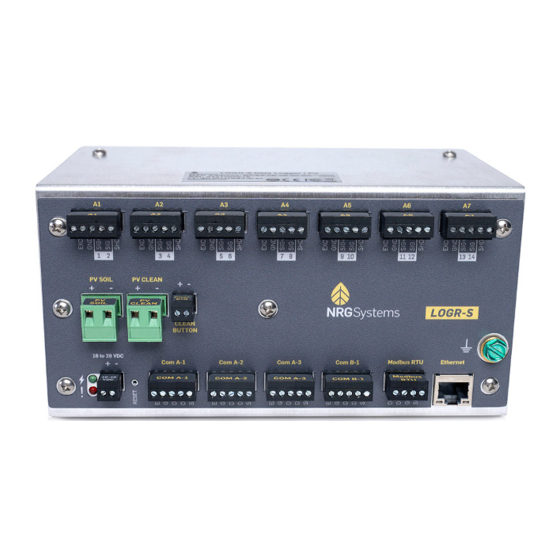
Interface, and Error! Reference source not found. for physical installation & wiring. Unpacking LOGR Confirm that you have received all components by comparing your order to the packing list included with your shipment. Immediately contact NRG Systems if any of the components are missing. Components Map NRG_LOGR-S_Manual support@nrgsystems.com | Page 10... - Page 11 NRG Product Manual LOGR-S Data Logger Each LOGR can be identified by the label on the top of the case, which contains the “NRG LOGR” model name, serial number (9431XXXXXX) and MAC Address. Serial Number & Logger Identification label Seven ports can support up to fourteen (14) single ended sensors, or Analog Channel Ports up to seven (7) differential sensors.
-
Page 12: Power Source
NRG Product Manual LOGR-S Data Logger Power Source LOGR requires a DC power supply of 16 to 28 V DC and consumes up to 4 A of current at 16 V when supplying power to attached smart sensors. Nominal supply voltage is 16 V, and the unit contains no boost regulators. -
Page 13: Section 3 | Pre-Installation Preparation
NRG Product Manual LOGR-S Data Logger SECTION 3 | PRE-INSTALLATION PREPARATION While LOGR is easy to set up, it is a good idea to get familiar with the system before going to the installation site. The following sections provide an overview of the software you will use to prepare your LOGR system for field installation. -
Page 14: Network Settings Configuration
NRG Product Manual LOGR-S Data Logger Network Settings Configuration Configuring the IP Address To secure your LOGR unit, it can be set to use DHCP for use on a network containing a DHCP server or use a static IP address (default option). To set the IP address, navigate to the Logger Menu at the top of the window and select Network Settings from the drop-down options. - Page 15 NRG Product Manual LOGR-S Data Logger When completed select the yellow Apply button, then confirm values are correct and select the Confirm button on the resulting Network Address Confirmation screen. LOGR takes about 10 seconds to confirm the settings change and will emit a beep when complete.
-
Page 16: Modbus Rtu
NRG Product Manual LOGR-S Data Logger Modbus RTU LOGR has an available Modbus RTU Client Port which enables the logger to be used with a Modbus server to query the registers in the SCADA map. To configure this port: Navigate to the Logger menu at the top of the page and select Network Settings from the drop- down options. -
Page 17: Ntp Server
NRG Product Manual LOGR-S Data Logger NTP Server For improved time accuracy, an NTP server can be configured for daily time updates. To configure: Navigate to the Logger menu at the top of the page and select Time Synchronization from the drop- down options. -
Page 18: System Configuration
NRG Product Manual LOGR-S Data Logger System Configuration Navigate to the Logger menu at the top of the page and select System Configuration from the drop- down options. Site Properties This field contains the name for the site. A site description of up to 32 characters can be entered. -
Page 19: Date And Time
NRG Product Manual LOGR-S Data Logger Date and Time The LOGR clock’s current time is displayed. Verify that this is the Device Time (Local Logger) current time in the local time zone in standard time (not “daylight- saving” time). Reference Time is the PC clock’s current time, displayed in UTC. -
Page 20: Channel Configuration & Data Collection
NRG Product Manual LOGR-S Data Logger Channel Configuration & Data Collection Analog Sensors LOGR provides seven ports for a total of fourteen analog channel options. These are used for measuring parameters including solar radiation, PV temperature, ambient temperature, barometric pressure, relative humidity, and more. The LOGR analog sensor ports have 12 V excitation with a limit of 50 mA per port. -
Page 21: Analog Channel Configuration
NRG Product Manual LOGR-S Data Logger Analog Channel Configuration Navigate to the Sensor menu at the top of the page and select Analog Channels from the drop-down options. Select Configure next to the channel of your choice. Selecting Configure for a specific channel will send you to the Analog Channel Configuration page for the specified channel. - Page 22 NRG Product Manual LOGR-S Data Logger Enter sensor height in meters. Enter the elevation angle & azimuth angle. Select Done when all relevant values have been entered to return to the Analog Channels page. Repeat with the remaining occupied analog sensor channels.
- Page 23 NRG Product Manual LOGR-S Data Logger To confirm the newly configured channels, scroll to the bottom of the page and click the yellow Save button in the bottom right corner. NRG_LOGR-S_Manual support@nrgsystems.com | Page 23 Rev. 1.0 5 November 2021...
-
Page 24: Modbus Rtu Serial Sensor Configuration
NRG Product Manual LOGR-S Data Logger Modbus RTU Serial Sensor Configuration LOGR supports up to 12 Modbus RTU sensors (6 on COM-A and 6 on COM-B) and 24 measurands in total. Do not connect more than 6 RTU sensors and gather 12 measurands per COM port. Both one second and statistical (average, max, min, and standard deviation) are available via Modbus registers. -
Page 25: Serial Channel Configuration
NRG Product Manual LOGR-S Data Logger Serial Channel Configuration To configure LOGR with your serial sensors: Navigate to the Sensor menu at the top of the page and select Serial Sensor Setup from the drop- down options. Check the “Configured” checkbox. - Page 26 NRG Product Manual LOGR-S Data Logger Saving the Serial Sensor Setup page will automatically send you to the Serial Channels page to specify the desired Measurands for the sensor. To configure serial channels: Select the desired previously configured sensor from the Sensor drop-down menu. This will automatically check the Enabled checkbox in the first column for the channel.
- Page 27 NRG Product Manual LOGR-S Data Logger After saving the channel configurations, the Web Interface will automatically route to the Sensor Outputs home page where Active channels report live data. The drop-down menu at the top right corner of the table allows alternative views of All, Active, Inactive, and Unconfigured channels.
-
Page 28: Pv Soiling Configuration
NRG Product Manual LOGR-S Data Logger PV Soiling Configuration LOGR uses the NREL Soiling Method to measure and provide a Daily Soiling Ratio, which requires a plane-of-array (POA) irradiance sensor in addition to the two PV panels. Terminal ports on the front panel of LOGR are provided for landing wires from “PV Soil”... -
Page 29: Sensor Configuration Reset
NRG Product Manual LOGR-S Data Logger Navigating to the Sensor menu at the top of the page and selecting Soiling Ratio Setup from the drop- down options also displays the date and time of the last panel cleaning. That cleaning timestamp is collected on this page and in the corresponding Modbus Register either when the yellow Clean Panel (virtual) button is clicked on the page, or when the physical “Clean Panel”... -
Page 30: Data Storage
NRG Product Manual LOGR-S Data Logger Data Storage To retrieve real-time data via Modbus TCP the logger should be connected to a SCADA network. The Modbus registers are pre-defined, allowing repeatable and streamlined data acquisition configuration. There is a backup of data contained on a non-removeable 8 GB microSD card embedded within the LOGR. - Page 31 NRG Product Manual LOGR-S Data Logger To update LOGR firmware using the web server, click the Browse button, navigate to and open a valid .bfw firmware file. Click the yellow Upload button. The LOGR will beep to confirm the action has been accepted by resetting and returning the web server to the Sensor Outputs home page.
-
Page 32: Ftp
NRG Product Manual LOGR-S Data Logger LOGR has a built in FTP client capable of picking up a command.ini file from a local FTP server. Command files can be used to save sensor configurations, unit configurations, update the device firmware (which can also be completed using the web server), and rebooting the logger. -
Page 33: Command File Options
NRG Product Manual LOGR-S Data Logger Command File Options Command Type Description Contents Reboot This file commands the LOGR to reboot. Note that this command [command] retains ethernet settings and command = reboot does not return the unit to the default IP Address. - Page 34 NRG Product Manual LOGR-S Data Logger Import Unit Configuration To import a formerly exported [command] unit configuration file to a LOGR, command = import unit this command file can be placed config on the FTP server. Ensure that [file parameters]...
- Page 35 NRG Product Manual LOGR-S Data Logger Hukseflux SR30 Heater Control This file can be placed on the FTP server to control the heater of the Hukseflux SR30 pyranometer. As a default, the sensor fan is always on. The ambient temperature used for thee SR30...
-
Page 36: Diagnostics
NRG Product Manual LOGR-S Data Logger Diagnostics LOGR tracks all major voltages and currents in the system for diagnostic purposes and real time values can be viewed in the webserver. Navigate to the Status menu at the top of the page and select Diagnostics from the dropdown options. -
Page 37: Analog Diagnostics
NRG Product Manual LOGR-S Data Logger Analog Diagnostics This section contains voltage and current information from the analog board of LOGR; these values are constantly monitored. Measurements within normal limits display a corresponding green status circle, while measurements not within tolerance show a red status circle to indicate an error condition. -
Page 38: Status Registers
NRG Product Manual LOGR-S Data Logger Status Registers LOGR constantly monitors various parameters and functions. Navigating to the Status menu at the top of the page and selecting Status Registers from the dropdown menu will display several status registers. All registers are available via SCADA; however, the critical parameters (Modbus Registers 32 and 34) are displayed on this page and can be reviewed for major function faults. -
Page 39: Section 4 | Field Installation
NRG Product Manual LOGR-S Data Logger SECTION 4 | FIELD INSTALLATION Grounding & Lightning Considerations Properly grounding your system helps protect your logger, sensors, and data. It is your responsibility to provide proper earth grounding for the tower, logger, and sensors. All warranties on NRG instruments and sensors are voided if your system is not properly grounded. -
Page 40: Mounting
NRG Product Manual LOGR-S Data Logger Mounting Within a shelter box, LOGR mounts onto a 35mm DIN Rail with a pair of removeable insulating clips (included). To install LOGR onto 35 mm DIN Rail: 1. Anchor the bottom of the black attachment clips on the back of the LOGR onto the bottom edge of the DIN rail by angling the unit. -
Page 41: Required Tools
The table below contains types of strain reliefs offered by NRG Systems, although other types may be sourced elsewhere. -
Page 42: Connecting Sensor Wires To Logr
NRG Product Manual LOGR-S Data Logger Connecting Sensor Wires to LOGR Two single ended sensors can be connected to each analog port, or one differential sensor. Connect the individual sensor wires to the supplied terminal plugs. Note that these terminal plugs are removeable and directional. -
Page 43: Wiring Map
NRG Product Manual LOGR-S Data Logger Wiring Map Refer to this diagram to connect standard sensors to the LOGR or refer to the manufacturer’s instructions for each sensor. NRG_LOGR-S_Manual support@nrgsystems.com | Page 43 Rev. 1.0 5 November 2021... - Page 44 NRG Product Manual LOGR-S Data Logger NRG_LOGR-S_Manual support@nrgsystems.com | Page 44 Rev. 1.0 5 November 2021...
-
Page 45: Logger Data Acquisition
NRG Product Manual LOGR-S Data Logger Logger Data Acquisition LOGR starts recording data and delivering it to the SCADA system as soon as it is powered up. A backup of all SCADA data is stored on an embedded microSD card installed inside the logger. If this data is needed as a backup or to send to NRG Technical Services for troubleshooting, it can be exported to the FTP server either with a command file or via the webserver. - Page 46 NRG Product Manual LOGR-S Data Logger The logger is now configured to transfer to/from the local FTP server. NRG_LOGR-S_Manual support@nrgsystems.com | Page 46 Rev. 1.0 5 November 2021...
-
Page 47: File Types
NRG Product Manual LOGR-S Data Logger File Types The files stored on the internal microSD card are a backup which can be used to backfill a SCADA database or for troubleshooting purposes. Much of the information stored in these files is available on the SCADA registers. -
Page 48: File Export
NRG Product Manual LOGR-S Data Logger File Export Alternatively, data files can be sent on demand, when needed, to the FTP server. In the File Export box, select a Start Date and End Date for a range to retrieve data files. The Start Date must precede or equal the End Date. -
Page 49: Section 5 | Communication & Data
NRG Product Manual LOGR-S Data Logger SECTION 5 | COMMUNICATION & DATA Modbus Network & Data Flow NRG_LOGR-S_Manual support@nrgsystems.com | Page 49 Rev. 1.0 5 November 2021... -
Page 50: Demo Client
NRG Product Manual LOGR-S Data Logger Demo Client The Modbus Demo Client is a free desktop software utility that facilitates installation where configuration of the LOGR Modbus server is required. The utility allows the user to read real-time values from the LOGR registers. -
Page 51: Export File Format
NRG Product Manual LOGR-S Data Logger Export File Format Data collected and stored by the LOGR system is comprised of a sensor sample data file, a diagnostic data file, and an event log. These data are exported in a human-readable format as plain ASCII text. - Page 52 NRG Product Manual LOGR-S Data Logger Example exported data file: NRG_LOGR-S_Manual support@nrgsystems.com | Page 52 Rev. 1.0 5 November 2021...
- Page 53 NRG Product Manual LOGR-S Data Logger Samples Only data file: Stats Only data file: NRG_LOGR-S_Manual support@nrgsystems.com | Page 53 Rev. 1.0 5 November 2021...
- Page 54 NRG Product Manual LOGR-S Data Logger Stats and Samples data file: Diagnostic data file format is also provided in plain text and consists of statistical data for MCU and analog sensor boards. Diagnostic data for the MCU board: • Raw power in •...
- Page 55 NRG Product Manual LOGR-S Data Logger Event log file format is also provided in plain text and consists of information, activity, and fault events that could be useful to users and NRG technicians. A healthy LOGR unit will generate very small event files.
-
Page 56: Section 6 | Power Systems
NRG Product Manual LOGR-S Data Logger SECTION 6 | POWER SYSTEMS Powering the LOGR Logger The LOGR data logger requires 16 to 36 V DC power. The logger typically draws 75 mA at 16 V (1.2 W) when unloaded. Powering Sensors LOGR also provides regulated 12 V DC power outputs at each serial sensor port and up to 50 mA per analog sensor port. -
Page 57: Appendix A | Technical Specifications
NRG Product Manual LOGR-S Data Logger APPENDIX A | TECHNICAL SPECIFICATIONS Please see nrgsystems.com for up-to-date product specifications. Description Instrument type High utility data logger and real-time sensor interface Applications Solar resource monitoring Data Collection Sampling interval 1 Hz (IEC 61724-1 compliant) - Page 58 NRG Product Manual LOGR-S Data Logger • Web-based user interface via Ethernet connected computing device with web browser Configuration User interface • Recessed reset button on front panel • Audible beeper for user feedback Integrated wiring panel featuring removable terminal blocks: •...
-
Page 59: Appendix B | Modbus Map
NRG Product Manual LOGR-S Data Logger APPENDIX B | MODBUS MAP Address Offset Description Type 0 Map Version UnsignedInteger32BitL 2 Float Format 12345678 FloatingPoint32BitL 4 UInt32 Format 123456789 UnsignedInteger32BitL 6 UInt16 Format 12345 UnsignedInteger32BitL 8 posix Time UnsignedInteger32BitL 10 SD Card Free Space (KB) - Page 60 NRG Product Manual LOGR-S Data Logger 10000 0 Year UTC UnsignedInteger32BitL 10002 2 Month UTC UnsignedInteger32BitL 10004 4 Day UTC UnsignedInteger32BitL 10006 6 Hour UTC UnsignedInteger32BitL 10008 8 Minute UTC UnsignedInteger32BitL 10010 10 Second UTC UnsignedInteger32BitL 10012 12 iShortCircuitClean FloatingPoint32BitL...
- Page 61 NRG Product Manual LOGR-S Data Logger 10164 24 Serial Scaled Channel 113 FloatingPoint32BitL 10166 26 Serial Scaled Channel 114 FloatingPoint32BitL 10168 28 Serial Scaled Channel 115 FloatingPoint32BitL 10170 30 Serial Scaled Channel 116 FloatingPoint32BitL 10172 32 Serial Scaled Channel 117...
- Page 62 NRG Product Manual LOGR-S Data Logger 15036 36 Analog Stats Channel 4 Average FloatingPoint32BitL 15038 38 Analog Stats Channel 4 Min FloatingPoint32BitL 15040 40 Analog Stats Channel 4 Max FloatingPoint32BitL 15042 42 Analog Stats Channel 4 SD FloatingPoint32BitL 15044 44 Analog Stats Channel 5 Average...
- Page 63 NRG Product Manual LOGR-S Data Logger 15116 116 Analog Stats Channel 14 Average FloatingPoint32BitL 15118 118 Analog Stats Channel 14 Min FloatingPoint32BitL 15120 120 Analog Stats Channel 14 Max FloatingPoint32BitL 15122 122 Analog Stats Channel 14 SD FloatingPoint32BitL 15460 0 Serial Stats Channel 101 Average...
- Page 64 NRG Product Manual LOGR-S Data Logger 15532 72 Serial Stats Channel 110 Average FloatingPoint32BitL 15534 74 Serial Stats Channel 110 Min FloatingPoint32BitL 15536 76 Serial Stats Channel 110 Max FloatingPoint32BitL 15538 78 Serial Stats Channel 110 SD FloatingPoint32BitL 15540 80 Serial Stats Channel 111 Average...
- Page 65 NRG Product Manual LOGR-S Data Logger 15612 32 Serial Stats Channel 120 Average FloatingPoint32BitL 15614 34 Serial Stats Channel 120 Min FloatingPoint32BitL 15616 36 Serial Stats Channel 120 Max FloatingPoint32BitL 15618 38 Serial Stats Channel 120 SD FloatingPoint32BitL 15620 40 Serial Stats Channel 121 Average...
- Page 66 NRG Product Manual LOGR-S Data Logger 15884 40 Calculated Stats Channel 306 Average FloatingPoint32BitL 15886 42 Calculated Stats Channel 306 Min FloatingPoint32BitL 15888 44 Calculated Stats Channel 306 Max FloatingPoint32BitL 15890 46 Calculated Stats Channel 306 SD FloatingPoint32BitL 15892 48 Calculated Stats Channel 307 Average...
- Page 67 NRG Product Manual LOGR-S Data Logger 16060 40 MCU Diag VSense COM-A EXC Average FloatingPoint32BitL 16062 42 MCU Diag VSense COM-A EXC Min FloatingPoint32BitL 16064 44 MCU Diag VSense COM-A EXC Max FloatingPoint32BitL 16066 46 MCU Diag VSense COM-A EXC SD...
- Page 68 NRG Product Manual LOGR-S Data Logger 16244 48 Analog Diag VSense-15V Average FloatingPoint32BitL 16246 50 Analog Diag VSense-15V Min FloatingPoint32BitL 16248 52 Analog Diag VSense-15V Max FloatingPoint32BitL 16250 54 Analog Diag VSense-15V SD FloatingPoint32BitL 16252 56 Analog Diag ISense 12V Average...
-
Page 69: Appendix C | Declaration Of Conformity
NRG Product Manual LOGR-S Data Logger APPENDIX C | DECLARATION OF CONFORMITY NRG_LOGR-S_Manual support@nrgsystems.com | Page 69 Rev. 1.0 5 November 2021... - Page 70 NRG Product Manual LOGR-S Data Logger NRG_LOGR-S_Manual support@nrgsystems.com | Page 70 Rev. 1.0 5 November 2021...
-
Page 71: Appendix D | Warranty
LOGR-S Data Logger APPENDIX D | WARRANTY NRG Systems (NRG) warrants its products for a period of two years from date of original purchase solely for the benefit of the original consumer purchaser. If this product is determined to be defective in materials or workmanship, NRG will, at NRG’s option, repair or replace this product without charge. - Page 72 Send your item to NRG Systems "Delivery Duty Paid" (see address below) using a door-to-door courier service such as UPS, FedEx, or DHL. If the repair is not urgent, please send your package by Airmail.
-
Page 73: Appendix E | References
NRG Systems will send you a shipment advisement when the repaired item is shipped. US Customers Please see items 1, 4, and 5 above. Send your item(s) to NRG Systems “Freight Prepaid and Insured.” Shipments sent freight collect will not be accepted by NRG Systems. APPENDIX E | REFERENCES Deceglie, M.
Need help?
Do you have a question about the LOGR-S and is the answer not in the manual?
Questions and answers