
Related Manuals for Orisec CK-60


Summary of Contents for Orisec CK-60
- Page 1 Master User Guide CK-10, CT-10, CP-10, CK-20, CT-20, CP-20, CP-30, CP-50, CK-60, CT-60, CP-60, CP-100 & CP-200 Designed and Manufactured in the United Kingdom...
-
Page 2: Table Of Contents
Contents About your Security System ....................4 Introduction ............................. 4 About this Manual ..........................4 Alarm Transmission System ........................ 4 Zones and Areas ............................ 4 Access code ............................. 4 NFC Tags ..............................5 Keypads ..............................5 Emergency Keys ............................. 8 Operating your Security System .................. - Page 3 Print Log ..............................25 System Tests ............................31 Test Bell & Strobe ..........................32 Walk Test Zones ...........................33 View Inactive Zones ..........................34 View Zone Status ..........................35 View Module Status ..........................36 Do a Test Call ............................37 Review Voice Messages ........................37 Send SMS Message ..........................38 Change Settings ...........................39 Set Time &...
-
Page 4: About Your Security System
1. About your Security System Introduction Your security system is made up of several component parts comprising of a control panel, one or more remote keypads, external sounder and various detection devices that are connected to either the control panel or zone expansion modules. The control panel houses the system’s electronics and stand-by battery and is normally installed out of sight in a utility room or under stairs cupboard etc. -
Page 5: Nfc Tags
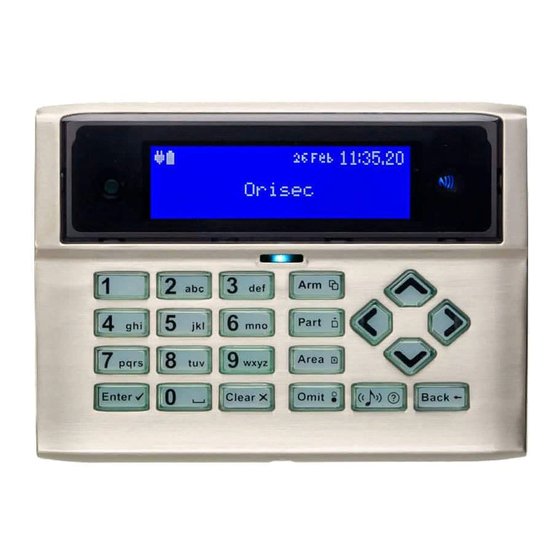
Your access code may not allow you to access certain system functions. For instance, if your code is only allowed to arm the system you will not be able to disarm the system, once the system is armed. NFC Tags NFC tags can be assigned to users of the system. - Page 6 Keypad Layout: CK-10, CK-20, CK-60, RK-500, RK-550, MK-700 & RK-700 LCD display NFC reader – present your NFC tag in this area (not on CK-10 or CT-10) Status Icons System status LED Ambient light sensor – used automatically adjusts the keyboard and LCD backlight level Keyboard –...
- Page 7 Touchscreen Keypad Layout: CT-10, CT-20, CT-60, TK-650 Full colour touch display NFC Reader – present your NFC tag in this area (not on CK-10 or CT-10) Status Icons System status LED Touch Keypad buttons Function Arm system Part arm system Area arm system Selection button Chime tone selection...
-
Page 8: Emergency Keys
Status Icons The system status area on the display is used to show the following information: Status Icon Indicates Battery is charging / is charged #$%K Mains power is connected Mains power is disconnected & External strobe is flashing External bell is sounding Chime is enabled Wi-Fi module connected GSM module connected... - Page 9 Emergency Alarm Keys Fire Press & Panic Alarm (PA) Press & Medical Press & Touch Keypad Emergency Keys To activate the emergency keys on your touch screen keypad you will need to be on the Home screen: From the top part of the screen select one of the emergency functions, for example ‘Fire’: You will then be prompted to press the Fire Alarm icon, and then select the icon again to confirm the activation.
- Page 10 Press the ‘CONFIRM’ icon to generate the selected emergency or press the ‘Back’ icon to cancel.
-
Page 11: Operating Your Security System
2. Operating your Security System Introduction Before attempting to operate your security system, please ensure that you have familiarised yourself with the procedures covered in this section of the manual. User Menu On entering a valid access code or presentation of a tag, the keypad will display the ‘User Menu’. -
Page 12: Full Arming Your Security System
Full Arming Your Security System The full arming mode is used for protecting all detection zones within your allocated areas and is normally used when leaving the premises or area unoccupied. Before attempting to full arm, check that your areas are ready for arming. To full arm your area(s), please proceed as follows: Enter code or present tag to select the user menu. -
Page 13: Part Arming Your Security System
Part Arming your Security System The part arming mode only protects predefined detection zones. The system has 3 ‘Part arm’ modes which allows for flexible arming configurations, e.g., ‘Part arm 1’ could be configured to arm only downstairs zones, whereas ‘Part arm 2’ could be configured to arm only perimeter zones. -
Page 14: Disarming Your Security System
Disarming your security system When the system or area is armed, you must enter the protected area via the designated entry route. Upon entering the premises, the entry timer and entry tone will start. To successfully disarm the alarm, a valid access code or tag must be entered before the entry timer expires. To disarm your area(s), please proceed as follows: Enter the protected area by the designated entry point, the entry tone will sound and the keypad will show the following screen:... -
Page 15: Area Full Arming
Area full arming Zones can be grouped together to make ‘area sets’. Area sets are often used in multi tenanted buildings where there is a communal entrance and separate living spaces/areas of work. Users can arm individual or multiple area sets. To full arm selected areas, please proceed as follows: Enter code or present tag to select the user menu. -
Page 16: Area Part Arming
Area part arming Zones can be grouped together to make ‘Area Sets’. Area Sets are often used in multi tenanted houses where there is a communal entrance and separate living spaces. Users can arm individual or multiple area sets. To part arm selected areas, please proceed as follows: Enter your code or present tag to select the user menu. -
Page 17: Area Disarming
Area disarming Normally when entering a protected area via the designated entry route, the area is disarmed after a valid access code or tag presentation. Sometimes it is desirable to disarm one or more areas before entering them via the designated entry route. To disarm your selected areas, please proceed as follows: The keypad will show the areas that are currently full armed: Enter your code or present tag, the ‘disarm areas’... -
Page 18: Resetting After An Alarm
Resetting after an alarm To reset after an alarm has occurred, please proceed as follows: If your system has gone into an alarm condition, the screen will alternate between the following two displays: Enter your code or present tag to silence any internal and external sounders. The reason for the alarm will then be displayed on the keypad screen. -
Page 19: Resetting After A Fault Condition
Resetting after a Fault Condition To reset after a fault has occurred, please proceed as follows: If your system has generated a fault condition, the display will indicate the fault that has occurred. For example, if there is a fault with the battery, the following will display: Enter your code or present your tag to the keypad. -
Page 20: Omitting Zones
Omitting Zones Zones can be omitted to temporarily prevent them from causing an alarm either during the disarmed mode (24hr zones) or prior to arming the system. To omit one or more zones, please proceed as follows: Enter code or present tag to select the user menu. From the user menu, use the keys to scroll to ‘Omit zones’: Press... -
Page 21: Changing Your Code
Changing Your Code User codes are unique to each user and can be 4,5 or 6 digits in length. Users can change their code at any time by following the procedure below: Before changing your code, it is strongly recommended to note the new code. If you forget your code later it must be changed by a master user of the system or the installation company. -
Page 22: Turn Chime On/Off
Turn chime on/off This option allows the chime feature to be turned on or off for each area. If the chime feature is switched on, then monitored zones that are activated during the disarmed state will cause the system to generate a chime response. See Alter chime zone on page 46 for available chime responses. -
Page 23: System Event Logs
System Event Logs The system event logs menu contains options for the viewing and printing of various event data that is recorded by your system. Enter your code or present your tag to select the user menu. From the user menu, use the arrow keys to scroll down to ‘View System Log’: Press to select, the ‘System Event Logs’... -
Page 24: View Event Log
View event log All system events such as arming, disarming, alarm and faults are recorded in the system log along with the date and time. Ensure that the ‘View event log’ option is selected from the ‘System Event Logs’ menu: Scroll back and forward through the log using the keys. -
Page 25: View Chime Log
View chime log Displays up to the last 50 zones that have chimed. Ensure that the ‘View chime log’ option is selected from the ‘System Event Logs’ menu: Scroll back and forward through the chime log using the keys. View Log Screen Information Line 1: Not used. - Page 26 Log Event Description Intruder Alarm XX Intruder alarm activated by zone XX. Intruder Restore XX Intruder zone XX restore. Perimeter Alarm XX Perimeter alarm activated by zone XX. Perimeter Restore XX Perimeter zone XX restore. 24Hr Alarm XX 24-hour alarm activated by zone XX. 24Hr Restore XX 24-hour zone XX restore.
- Page 27 Log Event Description Low Battery Restore XX Low battery alarm on zone XX has restored. Omit Key Active XX Key omits activated by zone XX. Omit Key Restore XX Key omits by zone XX has restored. Keyswitch Active XX Keyswitch connected to zone XX is active. Keyswitch Restore XX Keyswitch connected to zone XX has restored.
- Page 28 Log Event Description System Disarmed System disarmed. Arming Failed Arming failed. Armed With ATS Fault The system was armed with an Alarm Transmission System (ATS) fault. Auto Armed The system was automatically armed. Auto Disarmed The system was automatically disarmed. Remote Armed The system was automatically armed remotely.
- Page 29 Log Event Description Expander XX Found Expander XX on network found. Bell X Lost Network Bell X on network lost. Bell X Found Network Bell X on network found. Walktest Started User walk test mode started. Walktest Ended User walk test mode ended. Bell Test Started User bell test started.
- Page 30 Log Event Description Tag PA XX Alarm PA alarm triggered by XX tag. Radio Output XX Flt The control panel has detected a fault on radio output XX. Alarm Reset Alarm has been reset. RNRR Reset Random Number Remote Reset (A reset has been performed remotely) Zone XX on Test Zone XX has been put on soak test.
-
Page 31: System Tests
System Tests The system tests menu contains multiple different tests and diagnostics that can be performed on the system to ensure correct operation of the security system. Enter your code or present tag to select the user menu. From the user menu, use the arrow keys to scroll down to ‘System tests’: Press to select, the ‘System tests’... -
Page 32: Test Bell & Strobe
Test Bell & Strobe This menu allows you to test the external bell, strobe, internal speaker, user controlled outputs and the backlight on external sounders. Ensure that the ‘Test bell & Strobe’ menu is selected, see page 31: Use the keys to change between the options and then keys to toggle the selected option on and off. -
Page 33: Walk Test Zones
Walk Test Zones This menu allows the programmed zones to be walk tested to ensure they are activating when required. Ensure that the ‘Walk test zones’ menu is selected, see page 31: Activate the zones by walking in front of movement detectors and opening doors or windows that have sensor fitted. -
Page 34: View Inactive Zones
View Inactive Zones This menu allows zones that have been inactive for a period to be viewed. Ensure that the ‘View inactive zones’ menu is selected, see page 31: View Inactive Zones Screen Information Line 1: How many zones have been inactive for the selected period. Line 2: A scrolling list of inactive zones and the current zone status. -
Page 35: View Zone Status
View Zone Status This menu allows each zone to be independently monitored and viewed. Ensure that the ‘View zone status’ menu is selected, see page 31: View Zone Status Screen Information Line 1: Zone number and any programmed zone text. Line 2: The status of the zone, including resistance (if applicable) and zone count (how many times the zone has activated). -
Page 36: View Module Status
View Module Status This menu allows you to view the status of any communication modules installed on the system. Ensure that the ‘View module status’ menu is selected, see page 31: GSM Module Screen Information Line 1: If the module is currently ‘Fitted’ or ‘Not fitted’. Line 2: The most update signal reading from the sim card. -
Page 37: Do A Test Call
PSTN Module Screen Information Line 1: If the module is currently ‘Fitted’ or ‘Not fitted’ Line 2: The phoneline status ‘Good’, ‘Engaged’ or ‘Bad’. Line 3: The number of saved answer machine messages. Hold the key for 2 seconds to exit the menu. Do a Test Call Selecting this option will cause connected communication device to send a test call to the alarm receiving centre using the programmed in information (contact number / Account number/... -
Page 38: Send Sms Message
Use the keys to select the system message (1-75). Press to play the message. Send SMS Message This menu allows the user to send a SMS message to a telephone number of their choosing. The system must be fitted with either a GSM or PSTN module to use this feature. Ensure that the ‘Send SMS message’... -
Page 39: Change Settings
Change Settings The ‘Change settings’ menu contains options for personalising the system to your requirements. Enter your code or present tag to select the user menu. From the user menu, use the arrow keys to scroll down to ‘Change settings’: Press to select, the ‘Change settings’... -
Page 40: Set Time & Date
Set Time & Date This menu option lets you change the panel’s time and date. Ensure that the ‘Set time & date’ menu is selected, see page 39: Use the keys to select ‘Hours’, ‘Minutes’, ‘Seconds’, ‘Days’, ‘Months’ or ‘Years’. Then use the keys to change the value. -
Page 41: Add/Delete Users
Add/Delete Users This section covers programming of the system users. User 01 is the “Master” user which has a default code of 5678. Users 02 onwards can be programmed to any user type and default to “Not in Use”. ... - Page 42 Disarm only A Disarm only user can only access the disarming options within the user menu. Access Control An Access Control user is unable to access menus or privileges. Upon entering the code outputs programmed as 'Access' will trigger for the duration of the 'Access timer'. Access Latching An Access Latching user is unable to access menus or privileges.
- Page 43 Silent part arm The selected user will silently part arm the system. When the selected user part arms the system, the speakers are active during the exit procedure. Door Access When the selected user enters their code or presents their tag any outputs programmed as ‘Door Access’...
- Page 44 Doors: ‘Doors’ are used as a quick and simple access control solution; a keypad is referred to as a Door. By enabling a door on the selected user, once a valid code or tag has been presented by the user, the associated output trigger for the duration of the ‘Access timer’. Locked by chain The users access can be locked out using custom programmed ‘Chains’.
- Page 45 To add or edit users: Ensure that the ‘Add/Delete user’ menu is selected, see page 39: Use the keys to select the required function. Then use the keys to change the selected option. Hold the key for 2 seconds to exit the menu. To delete users: Ensure that the ‘Add/Delete user’...
-
Page 46: Alter Chime Zones
Alter chime zones All monitored zones can be configured to give the following chime response: No response. Tone 1 A single ‘de-da’ tone is generated. Tone 2 A double ‘de-da-do’ tone is generated. Tone 3 A triple descending musical tone is generated. Voice The zone is announced from the loudspeaker (if fitted), e.g., ‘Front Door’. -
Page 47: Coms Modules
Hold the key for 2 seconds to exit the menu. Coms Modules The control panel supports various communication modules (except CK-10 and CT-10). This menu allows you to configure the settings for each module. GSM Settings When a GSM Module is fitted the following options must be configured: APN Name The Access Point Name (APN) is used by the GSM network operator for IP packet data communication –... - Page 48 The control panel uses the ETSI ES 201 912 protocol 1 to send SMS message via a standard phone line. This protocol is not supported worldwide so please check with your telephone provider. If the SMS message feature is required, the SMS-Service Centre number must be configured.
-
Page 49: About
User codes in use PSTN module fitted or not fitted CM2 Module (CK-20, CT-20, CK-60, CT-60, CP-20, CP-60 only) ZX-5C and its software version (CP-30, CP-50, CP-100 & CP-200 only) Wi-Fi signal, IP address and port number ... -
Page 50: Additional Features
3. Additional Features Additional features can be enabled by the installation company and as such some options may not be available on your security system. To access the additional features whilst the system is in an unset state, press from the home screen and scroll through all enabled additional features. Please see a table for a full list off additional features available: Touch Feature... -
Page 51: Troubleshooting
4. Troubleshooting Message When I might see Potential reasons for Suggested methods to displayed on this message message resolve screen Zone 01 Active When attempting The zone is reporting back Check the device to ensure to arm to the main control panel it is not a door or window an open state that has been left open... -
Page 52: Touch-Tone Remote Control
5. Touch-Tone Remote Control Introduction When the control panel is fitted with a PSTN module, the system can be remotely controlled via any touch-tone telephone. Once the call is answered by the control panel you will be assisted by voice prompts to enter your normal access code, if the code is accepted a voice prompted menu is played to you. -
Page 53: Full Arm
To end the remote access session, enter on your touch-tone phone. *99# Full Arm To full arm your security system from a remote location, please proceed as follows: Access your security system as described in the “Remote Access” section. After the main menu, has finished playing, enter on your touch-tone phone. -
Page 54: Turn Remote Controlled Outputs On And Off
Turn Remote Controlled Outputs On and Off The control panel has 5 remote controlled outputs that can be switched on and off when the system is remotely accessed via a touch-tone telephone. Your installer will normally connect one or more of the remote-controlled outputs to control lighting etc. To turn on or off the remote-controlled outputs from a remote location, please proceed as follows: Access your security system as described in the “Remote Access”... -
Page 55: Installer Information
Installer Information Installation Company: Address: Telephone (Daytime): Telephone (Emergency): Installation Date: Email: Web site: Notes:... - Page 56 © 2020 INS022...
Need help?
Do you have a question about the CK-60 and is the answer not in the manual?
Questions and answers