
Related Manuals for Orisec CP-25


Summary of Contents for Orisec CP-25
- Page 1 CP-25 & CP-50 User Guide Designed and Manufactured in the United Kingdom www.orisec.co.uk...
- Page 2 ...
- Page 3 Notes ...
-
Page 4: Table Of Contents
Contents About your Security System ....................6 Introduction ............................6 About this Manual ..........................6 Alarm Transmission System ......................6 Zones and Areas ..........................6 Access code ............................6 NFC Tags .............................. 7 ... - Page 5 View chime log ..........................26 Print Log ............................. 26 System Tests ............................32 Test Bell & Strobe ..........................33 Walk Test Zones ..........................34 View Inactive Zones ........................35 View Zone Status ..........................36 View Module Status.........................
-
Page 6: About Your Security System
1. About your Security System Introduction Your security system is made up of several component parts comprising of a control panel, one or more remote keypads, external sounder and various detection devices that are connected to either the control panel or zone expansion modules. The control panel houses the system’s electronics and stand-by battery and is normally installed out of sight in a utility room or under stairs cupboard etc. -
Page 7: Nfc Tags
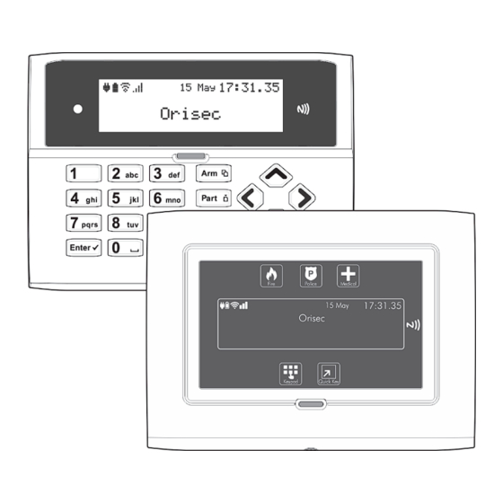
Your access code may not allow you to access certain system functions. For instance, if your code is only allowed to arm the system you will not be able to disarm the system, once the system is armed. NFC Tags NFC (Near Field Communication) tags can be assigned to users of the system. - Page 8 Keyed Keypad buttons Actions Arm system A Part arm system P Area arm system a Selection button E Chime tone selection Escape button Cancel button Touch Keypad Layout Full colour touch display NFC Reader – present your NFC tag in this area Status Icons System status LED...
- Page 9 Touch Keypad buttons Function Arm system Part arm system Area arm system Selection button Chime tone selection Escape button Cancel button Status Icons The system status area on the display is used to show the following information: Status Icon Indicates Battery is charging/ is charged...
-
Page 10: Emergency Keys
Emergency Keys The keypad provides 3 different emergency functions. Depending on the setup of your system, activation from these keys can alert the local police, key holders and security personal via your Alarm Receiving Centre (ARC). The emergency keys for each keypad can be individual enabled or disabled and may not be enabled on your installation due to local standards and police requirements. - Page 11 You will then be prompted to press the Fire Alarm icon, and then select the icon again to confirm the activation. This is in place to ensure it is a confirmed event and not an accidental button press: Press the ‘CONFIRM’ icon to generate the selected emergency or press the ‘Back’ icon to cancel.
-
Page 12: Operating Your Security System
2. Operating your Security System Introduction Before attempting to operate your security system, please ensure that you have familiarised yourself with the procedures covered in this section of the manual. User Menu On entering a valid access code or presentation of a tag the keypad will display the ‘User Menu’. This menu is used to perform all system operations including arming, disarming, testing and system configuration. -
Page 13: Full Arming Your Security System
Full Arming Your Security System The full arming mode is used for protecting all detection zones within your allocated areas and is normally used when leaving the premises or area unoccupied. Before attempting to full arm, check that your areas are ready for arming. To full arm your area(s), please proceed as follows: Enter code or present tag to select the user menu. -
Page 14: Part Arming Your Security System
Part Arming your Security System The part arming mode only protects predefined detection zones. The system has 3 ‘Part arm’ modes which allows for flexible arming configurations, e.g., ‘Part arm 1’ could be configured to arm only downstairs zones, whereas ‘Part arm 2’ could be configured to arm only perimeter zones. -
Page 15: Disarming Your Security System
Disarming your security system When the system or area is armed, you must enter the protected area via the designated entry route. Upon entering the premises, the entry timer and entry tone will start. To successfully disarm the alarm, a valid access code or tag must be entered before the entry timer expires. To disarm your area(s), please proceed as follows: Enter the protected area by the designated entry point, the entry tone will sound and the keypad will show the following screen:... -
Page 16: Area Full Arming
Area full arming Zones can be grouped together to make ‘area sets’. Area sets are often used in multi tenanted buildings where there is a communal entrance and separate living spaces/areas of work. Users can arm individual or multiple area sets. To full arm selected areas, please proceed as follows: Enter code or present tag to select the user menu. -
Page 17: Area Part Arming
Area part arming Zones can be grouped together to make ‘Area Sets’. Area Sets are often used in multi tenanted houses where there is a communal entrance and separate living spaces. Users can arm individual or multiple area sets. To part arm selected areas, please proceed as follows: Enter your code or present tag to select the user menu. -
Page 18: Area Disarming
Area disarming Normally when entering a protected area via the designated entry route, the area is disarmed after a valid access code or tag presentation. Sometimes it is desirable to disarm one or more areas before entering them via the designated entry route. To disarm your selected areas, please proceed as follows: The keypad will show the areas that are currently full armed: Enter your code or present tag, the ‘disarm areas’... -
Page 19: Resetting After An Alarm
Resetting after an alarm To reset after an alarm has occurred, please proceed as follows: If your system has gone into an alarm condition, the screen will alternate between the following two displays: Enter your code or present tag to silence any internal and external sounders. The reason for the alarm will then be displayed on the keypad screen. -
Page 20: Resetting After A Fault Condition
Resetting after a Fault Condition To reset after a fault has occurred, please proceed as follows: If your system has generated a fault condition, the display will indicate the fault that has occurred. For example, if there is a fault with the battery, the following will display: Enter your code or present your tag to the keypad. -
Page 21: Omitting Zones
Omitting Zones Zones can be omitted to temporarily prevent them from causing an alarm either during the disarmed mode (24hr zones) or prior to arming the system. Only the ‘Master’ and ‘Manager’ user types can omit zones. To omit one or more zones, please proceed as follows: Enter code or present tag to select the user menu. -
Page 22: Changing Your Code
Changing Your Code User codes are unique to each user and can be 4,5 or 6 digits in length. Users can change their code at any time by following the procedure below: Before changing your code, it is strongly recommended to note the new code. If you forget your code later it must be changed by a master user of the system or the installation company. -
Page 23: Turn Chime On/Off
Turn chime on/off This option allows the chime feature to be turned on or off for each area. If the chime feature is switched on, then monitored zones that are activated during the disarmed state will cause the system to generate a chime response. See Error! Reference source not found. on page Error! Bookmark not defined. -
Page 24: System Event Logs
System Event Logs The system event logs menu contains options for the viewing and printing of various event data that is recorded by your system. This menu is only available to the ‘Master’ and ‘Manager’ user types. Enter your code or present your tag to select the user menu. From the user menu, use the arrow keys to scroll down to ‘View System Log’: Press to select, the ‘System Event Logs’... -
Page 25: View Event Log
View event log All system events such as arming, disarming, alarm and faults are recorded in the system log along with the date and time. Ensure that the ‘View event log’ option is selected from the ‘System Event Logs’ menu: Scroll back and forward through the log using the U and D keys. -
Page 26: View Chime Log
View chime log Displays up to the last 50 zones that have chimed. Ensure that the ‘View chime log’ option is selected from the ‘System Event Logs’ menu: Scroll back and forward through the chime log using the U and D keys. View Log Screen Information Line 1: Not used. - Page 27 Log Event Description Intruder Alarm XX Intruder alarm activated by zone XX. Intruder Restore XX Intruder zone XX restore. Perimeter Alarm XX Perimeter alarm activated by zone XX. Perimeter Restore XX Perimeter zone XX restore. 24Hr Alarm XX 24-hour alarm activated by zone XX. 24Hr Restore XX 24-hour zone XX restore.
- Page 28 Log Event Description Low Battery Restore XX Low battery alarm on zone XX has restored. Omit Key Active XX Key omits activated by zone XX. Omit Key Restore XX Key omits by zone XX has restored. Keyswitch Active XX Keyswitch connected to zone XX is active. Keyswitch Restore XX Keyswitch connected to zone XX has restored.
- Page 29 Log Event Description System Disarmed System disarmed. Arming Failed Arming failed. Armed With ATS Fault The system was armed with an Alarm Transmission System (ATS) fault. Auto Armed The system was automatically armed. Auto Disarmed The system was automatically disarmed. Remote Armed The system was automatically armed remotely.
- Page 30 Log Event Description Expander XX Found Expander XX on network found. Bell X Lost Network Bell X on network lost. Bell X Found Network Bell X on network found. Walktest Started User walk test mode started. Walktest Ended User walk test mode ended. Bell Test Started User bell test started.
- Page 31 Log Event Description Tag PA XX Alarm PA alarm triggered by XX tag. Radio Output XX Flt The control panel has detected a fault on radio output XX. Alarm Reset Alarm has been reset. RNRR Reset Random Number Remote Reset (A reset has been performed remotely) Zone XX on Test Zone XX has been put on soak test.
-
Page 32: System Tests
System Tests The system tests menu contains multiple different tests and diagnostics that can be performed on the system to ensure correct operation of the security system. This menu is only available to the ‘Master’ and ‘Manager’ user types. Enter your code or present tag to select the user menu. From the user menu, use the arrow keys to scroll down to ‘System tests’: Press to select, the ‘System tests’... -
Page 33: Test Bell & Strobe
Test Bell & Strobe This menu allows you to test the external bell, strobe, internal speaker, user controlled outputs and the backlight on external sounders. Ensure that the ‘Test bell & Strobe’ menu is selected, see page 32: Use the keys to change between the options and then the U D... -
Page 34: Walk Test Zones
Walk Test Zones This menu allows the programmed zones to be walk tested to ensure they are activating when required. Ensure that the ‘Walk test zones’ menu is selected, see page 32: Activate the zones by walking in front of movement detectors and opening doors or windows that have sensor fitted. -
Page 35: View Inactive Zones
View Inactive Zones This menu allows zones that have been inactive for a period to be viewed. Ensure that the ‘View inactive zones’ menu is selected, see page 32: View Inactive Zones Screen Information Line 1: How many zones have been inactive for the selected period. Line 2: A scrolling list of inactive zones and the current zone status. -
Page 36: View Zone Status
View Zone Status This menu allows each zone to be independently monitored and viewed. Ensure that the ‘View zone status’ menu is selected, see page 32: View Zone Status Screen Information Line 1: Zone number and any programmed zone text. Line 2: The status of the zone, including resistance (if applicable) and zone count (how many times the zone has activated). -
Page 37: View Module Status
View Module Status This menu allows you to view the status of the communication modules installed on the system. Ensure that the ‘View module status’ menu is selected, see page 32: GSM Module Screen Information Line 1: If the module is currently ‘Fitted’ or ‘Not fitted’. Line 2: The most update signal reading from the sim card. -
Page 38: Do A Test Call
The system has 15 programmable voice messages; each message can be up to 16 seconds long. The messages can be recorded using the Orisec software and uploaded into the control panel. Alternatively, voice messages can be recorded from a telephone handset. -
Page 39: Send Sms Message
Use the keys to select the system message (1-75). Press to play R the message. Send SMS Message This menu allows the user to send a SMS message to a telephone number of their choosing. The system must be fitted with either a GSM or PSTN module to use this feature. Ensure that the ‘Send SMS message’... -
Page 40: Additional Features
3. Additional Features Additional features can be enabled by the installation company and as such some options may not be available on your security system. To access the additional features whilst the system is in an unset state, press L or R from the home screen and scroll through all enabled additional features. -
Page 41: Troubleshooting
4. Troubleshooting Message When I might see Potential reasons for Suggested methods to displayed on this message message resolve screen Zone 01 Active When attempting The zone is reporting back Check the device to ensure to arm to the main control panel it is not a door/ window an open state that has been left open... - Page 42 Notes ...
- Page 43 ...
- Page 44 Exceptional Design and Performance Orisec Ltd, 1 St Crispin Way, Haslingden, Lancashire, BB4 4PW, United Kingdom © Orisec Ltd 2017 INS023...
Need help?
Do you have a question about the CP-25 and is the answer not in the manual?
Questions and answers
I have changed batteries in alarm panel and am unsure have to reset alarm