Sign In
Upload
Download
Table of Contents
Contents
Add to my manuals
Delete from my manuals
Share
URL of this page:
HTML Link:
Bookmark this page
Add
Manual will be automatically added to "My Manuals"
Print this page
×
Bookmark added
×
Added to my manuals
Manuals
Brands
Bticino Manuals
Gateway
N4510C
Installation manual
Bticino N4510C Installation Manual
Smart with netatmo electric system
Hide thumbs
1
2
Table Of Contents
3
4
5
6
7
8
9
10
11
12
13
14
15
16
17
18
19
20
21
22
23
24
25
26
27
28
page
of
28
Go
/
28
Contents
Table of Contents
Bookmarks
Table of Contents
Table of Contents
General Features
Install a Smart with Netatmo Electric System
Associate the Connected Devices
Add a Connected Device
Add a Wireless Scenario Control
Associate a Wireless Light/Rolling Shutter Control to One or more Modular Connected Devices
Dissociate a Wireless Control from the Connected Devices
Reset to the Factory Settings
Use the App
Advertisement
Quick Links
1
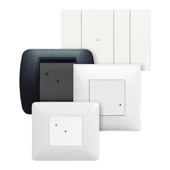
Install a Smart with Netatmo Electric System
Download this manual
Smart with Netatmo
electric system
Installation Manual
RA00185AB-05/21-PC
www.bticino.com
Table of
Contents
Previous
Page
Next
Page
1
2
3
4
5
Advertisement
Table of Contents
Need help?
Do you have a question about the N4510C and is the answer not in the manual?
Ask a question
Questions and answers
Related Manuals for Bticino N4510C
Gateway Bticino L4500C Manual
(4 pages)
Gateway Bticino NT4510C Installation Manual
Smart with netatmo electric system (28 pages)
Gateway Bticino FC80GT Installation Manual
With netatmo (30 pages)
Gateway Bticino FC80GT Installation Manual
Btdin with netatmo (30 pages)
Gateway Bticino FC80GT Manual
(4 pages)
Gateway Bticino FC80GCS Quick Start Manual
(2 pages)
Gateway Bticino F429G Quick Start Manual
(4 pages)
This manual is also suitable for:
Nt4510c
Bti-nt4510c-en
Bti-n4510c-en
Netatmo
Table of Contents
Save PDF
Print
Rename the bookmark
Delete bookmark?
Delete from my manuals?
Login
Sign In
OR
Sign in with Facebook
Sign in with Google
Upload manual
Upload from disk
Upload from URL


Need help?
Do you have a question about the N4510C and is the answer not in the manual?
Questions and answers