Table of Contents
Advertisement
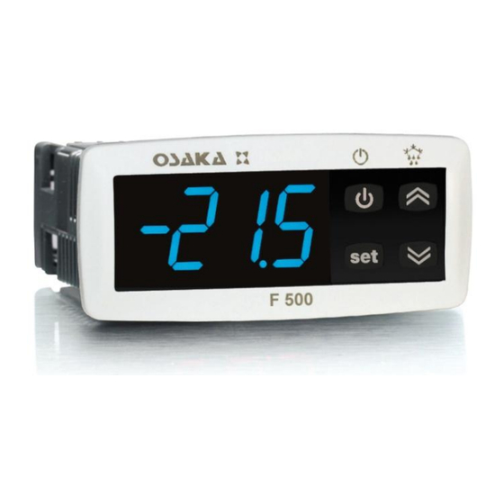
F 500/ F 500-RS
DIGITAL ELECTRONIC
REFRIGERATION UNITS
CONTROLLER
USER MANUAL
FOREWORD
This
manual
necessary for the product to be installed
correctly
maintenance and use; we therefore recommend
that the utmost attention is paid to the
following instructions and to save it.
This document is the exclusive property of
OSAKA which forbids any reproduction and divulgation , even
in part, of the document, unless expressly authorized.
OSAKA SOLUTIONS, SL reserves the right to make any formal
or functional changes at any moment and without any notice.
Whenever a failure or a malfunction of the device may cause
dangerous situations for persons, thing or animals, please
remember that the plant has to be equipped with additional
devices which will guarantee safety.
OSAKA and its legal representatives do not assume any
responsibility for any damage to people, things or animals
deriving from violation, wrong or improper use or in any case
not in compliance with the instrument's features.
INDEX
1
INSTRUMENT DESCRIPTION
1.1
GENERAL DESCRIPTION
1.2
FRONT PANEL DESCRIPTION
2
PROGRAMMING
2.1
FAST PROGRAMMING OF SET POINT
2.2
STANDARD MODE PARAMETERS PROGRAMMING
2.3
PARAMETER PROTECTION USING THE PASSWORD
2.4
CUSTOMIZED MODE PARAMETER PROGRAMMING
(PARAMETERS PROGRAMMING LEVEL)
2.5
RESET PARAMETERS TO DEFAULT VALUE/LEVEL
2.6
KEYBOARD LOCK FUNCTION
2.7
SETTING THE CURRENT TIME AND DATE
2.8
PROGRAMMING EVENTS TO OCCUR AT DEFINED
TIMES
2.9
DISPLAYING HACCP ALARMS
3
INFORMATION ON INSTALLATION AND USE
3.1
PERMITTED USE
3.2
MECHANICAL MOUNTING
3.3
ELECTRICAL CONNECTIONS
3.4
ELECTRICAL WIRING DIAGRAM
contains
the
information
and
also
instructions
– USER MANUAL – F 500 / F 500-RS – V.1 – Page 1
OSAKA
4
FUNCTIONS
4.1
ON / STAND-BY FUNCTION
"NORMAL"MODE, "ECONOMIC" MODE AND "TURBO"
4.2
MODE
4.3
MEASURING AND DISPLAY
4.4
DIGITAL INPUTS
4.5
OUTPUTS AND BUZZER CONFIGURATION
4.6
TEMPERATURE CONTROL
4.7
COMPRESSOR PROTECTION FUNCTION AND DELAY
AT POWER-ON
4.8
DEFROST CONTROL
4.8.1
AUTOMATIC DEFROST STARTS
4.8.2
MANUAL DEFROST
4.8.3
END DEFROST
4.8.4
DEFROSTS IN EVENT OF EVAPORATOR PROBE
ERROR
4.8.5
DEFROST DISPLAY LOCK
4.9
EVAPORATOR FANS CONTROL
4.10
ALARM FUNCTIONS
4.10.1 TEMPERATURE ALARMS
4.10.2 EXTERNAL ALARMS (DIGITAL INPUTS)
4.10.3 OPEN DOOR ALARM
4.11
HACCP FUNCTION (ALARM RECORDING)
4.11.1 HACCP TEMPERATURE ALARMS
4.11.2 HACCP POWER FAILURE (BLACK-OUT) ALARMS
4.11.3 HACCP ALARMS FROM DIGITAL INPUTS
FUNCTION OF KEYS "STAND-BY" AND "DOWN/AUX"
4.12
4.13
EVENTS THAT CAN BE PROGRAMMED TO OCCUR
AT DEFINED TIMES
4.14
RS 485 SERIAL INTERFACE
4.15
ACCESSORIES
4.15.1 PARAMETERS CONFIGURATION BY "KEY USB"
4.15.2 "X2" REMOTE DISPLAY
5
PROGRAMMABLE PARAMETERS TABLE
6
PROBLEMS , MAINTENANCE AND GUARANTEE
6.1
SIGNALLING
for
its
6.2
CLEANING
6.3
GUARANTEE AND REPAIRS
7
TECHNICAL DATA
7.1
ELECTRICAL DATA
7.2
MECHANICAL DATA
7.3
MECHANICAL DIMENSIONS, PANEL CUT-OUT AND
MOUNTING
7.4
FUNCTIONAL DATA
7.5
INSTRUMENT ORDERING CODE
1 - INSTRUMENT DESCRIPTION
1.1 - GENERAL DESCRIPTION
The F 500 / F 500-RS model is a digital electronic microprocessor
controller that can be used typically for refrigeration applications. It
has temperature control with ON/OFF regulation and control of
defrosting at defined times (Real Time Clock Defrosting), at time
intervals, by arrival at temperature or by length of time of continuous
compressor operation through stopping the compressor, electric
heating or hot gas/cycle inversion. The appliance has special
defrosting optimisation functions and functions to reduce the
amount of energy used by the controlled system.
The instrument has up to 4 relay outputs, up to 4 inputs
configurable for PTC, NTC and Pt1000 temperature probes, and 2
digital inputs. It can also be equipped with an internal buzzer for
acoustic notification of alarms; an RS485 serial communication
interface with MODBUS-RTU communication protocol; and a
calendar clock.
The clock allows you to define the times of defrosting events,
auxiliary output switching, switching of the regulating set point,
instrument on/off, etc. (max 14 daily and 98 weekly events)
Another feature of the calendar clock version of the instrument is
that it has the HACCP function which can store the last 10 alarms
that have occurred (alarm type, start, duration and temperature
peaks)
The 4 outputs can be used to control the compressor or the
temperature control device, the defroster, the evaporator fans and a
configurable auxiliary device (Light, Alarm, second evaporator, etc.)
Advertisement
Table of Contents

Related Manuals for Osaka F 500


Summary of Contents for Osaka F 500
- Page 1 MECHANICAL MOUNTING temperature control device, the defroster, the evaporator fans and a ELECTRICAL CONNECTIONS configurable auxiliary device (Light, Alarm, second evaporator, etc.) ELECTRICAL WIRING DIAGRAM – USER MANUAL – F 500 / F 500-RS – V.1 – Page 1 OSAKA...
-
Page 2: Front Panel Description
9 - Led FAN : Indicates fan output status on (on), off (off) or key pressed for 1 sec. until will show the code group. delayed after defrosting (flashing) – USER MANUAL – F 500 / F 500-RS – V.1 – Page 1 OSAKA... - Page 3 “c.CL” parameter, and to the current date using key, keep it pressed and press together also the key UP. the “c.dt” parameter. – USER MANUAL – F 500 / F 500-RS – V.1 – Page 1 OSAKA...
-
Page 4: Displaying Haccp Alarms
If the alarm is still ongoing at the time of its display, the data are d. 5 = Friday displayed but the alarm is not recognised. d. 6 = Saturday d. 7 = Sunday d. 8 = every day – USER MANUAL – F 500 / F 500-RS – V.1 – Page 1 OSAKA... - Page 5 - at times defined through the clock by programming events t.6 and temperatures, be used. Furthermore, the input cable of the (switch to Eco mode) and t.7 (switch to normal mode). For further – USER MANUAL – F 500 / F 500-RS – V.1 – Page 1 OSAKA...
- Page 6 (possible uses: wishes to lower the temperature of the products quickly after product probe, anti-freeze probe, etc.) loading the refrigerator. – USER MANUAL – F 500 / F 500-RS – V.1 – Page 1 OSAKA...
-
Page 7: Digital Inputs
The instrument outputs can be configured by the relative parameter “i.dS” alternately on the display. With this function mode, parameters “o.o1” , “o.o2”, “o.o3”, “o.o4”. – USER MANUAL – F 500 / F 500-RS – V.1 – Page 1 OSAKA... -
Page 8: Temperature Control
SPH. “SPH”); the intervention differential “r.d” (or “r.Ed” and/or “r.Hd”); = C3 (Cooling with three automatic modes) and the operating mode “r.HC”. – USER MANUAL – F 500 / F 500-RS – V.1 – Page 1 OSAKA... - Page 9 9 = Mon, Tue, Wed, Thur, Fri turning on last time (delay between switching-on). d.10 = Mon, Tue, Wed, Thur, Fri, Sat d.11 = Sat and Sun d.oF = none – USER MANUAL – F 500 / F 500-RS – V.1 – Page 1 OSAKA...
- Page 10 The automatic defrosting cycle can be ended by time or, if an evaporator probe is used (“EP” probe), when a temperature on the evaporator is reached. – USER MANUAL – F 500 / F 500-RS – V.1 – Page 1 OSAKA...
- Page 11 (the time “d.dE” is a security time-out) and in case is used the "Dynamic Intervals Defrost System” the interval is usually – USER MANUAL – F 500 / F 500-RS – V.1 – Page 1 OSAKA...
-
Page 12: Evaporator Fans Control
“F.LF” (temperature too temperature alarms are disabled beginning with instrument start-up cold). if the instrument is in an alarm condition on start-up. – USER MANUAL – F 500 / F 500-RS – V.1 – Page 1 OSAKA... -
Page 13: Open Door Alarm
If the alarm is still ongoing at the time of its display, the data are led and displaying on the display the label defined for the alarm displayed but the alarm is not recognised and cannot be cancelled. – USER MANUAL – F 500 / F 500-RS – V.1 – Page 1 OSAKA... - Page 14 = 2 - Pressing the key for at least 1 second, it is possible to select - Black-out duration ( E. = hours, e. = minutes) the mode Economic/Normal in rotation. Once selection has been – USER MANUAL – F 500 / F 500-RS – V.1 – Page 1 OSAKA...
- Page 15 X 3 4 n .1 X 3 4 n .2 X 3 4 n .N – 4 defrosts every working day at 7.00, 12.00, 17.00 and 22.00 – USER MANUAL – F 500 / F 500-RS – V.1 – Page 1 OSAKA...
-
Page 16: Programmable Parameters Table
Set Point (SP-SPE) 7= Switch on/ off (Stand - by) 8= “Turbo" cycle activation 9= Remote command of AUX output 10= Disable recording of HACCP alarms – USER MANUAL – F 500 / F 500-RS – V.1 – Page 1 OSAKA... - Page 17 0.01 ÷ 9.59 d.di Defrosting interval oF/ 0.01 ÷ 9.59 6.00 time for probe error (min.sec ) ÷ (hrs.min. ) ÷ 99.5 99.5 (min.sec.x10) (hrs.min.x10) – USER MANUAL – F 500 / F 500-RS – V.1 – Page 1 OSAKA...
- Page 18 9 = “Au” relative be recorded as an (min.sec ) ÷ without label HACCP alarm 99.5 10 = “cd” absolute ( =oF HACCP rec. (min.sec.x10) without label disable) – USER MANUAL – F 500 / F 500-RS – V.1 – Page 1 OSAKA...
- Page 19 / 1 / 2 / 3 / 4 t = event type STAND-BY: / 5 / 6 / 7 t.1 = Switch on oF= No function t.2 = Stand-by – USER MANUAL – F 500 / F 500-RS – V.1 – Page 1 OSAKA...
- Page 20 @ 25 °C) or NTC (103AT-2, 10K @ 25 °C) or Pt1000 (1000 @ 0° C); 2 digital inputs for free voltage contacts Output/s: up to 4 relay outputs (Out1 and Out2 are always present) – USER MANUAL – F 500 / F 500-RS – V.1 – Page 1 OSAKA...
- Page 21 Directive 37/2005 / EC (13485 aria / air, S, A, 1, - 50 ° C + 90 ° C when used with model 103AT11 NTC or PT1000 probe class B or better. – USER MANUAL – F 500 / F 500-RS – V.1 – Page 1 OSAKA...
Need help?
Do you have a question about the F 500 and is the answer not in the manual?
Questions and answers