Table of Contents
Advertisement
Quick Links
COMPACT
MICROPROCESSOR-BASED DIGITAL
ELECTRONIC FREEZER
CONTROLLER
Operating Instructions
FOREWORD
This
manual
necessary for the product to be installed
correctly and
maintenance
recommend that the utmost attention is paid
to the following instructions and to save it.
This document is the exclusive property of OSAKA which
forbids any reproduction and divulgation , even in part, of
the document, unless expressly authorized.
OSAKA reserves the right to make any formal or functional
changes at any moment and without any notice.
Whenever a failure or a malfunction of the device may
cause dangerous situations for persons, thing or animals,
please remember that the plant has to be equipped with
additional devices which will guarantee safety.
OSAKA . and its legal representatives do not assume any
responsibility for any damage to people, things or animals
deriving from violation, wrong or improper use or in any
case not in compliance with the instrument's features.
INDEX
1
INSTRUMENT DESCRIPTION
1.1
GENERAL DESCRIPTION
1.2
FRONT PANEL DESCRIPTION
2
PROGRAMMING
2.1
PROGRAMMING OF SET POINT
2.2
PARAMETERS PROGRAMMING
2.3
PARAMETER
PASSWORD AND KEYBOARD LOCK FUNCTION
2.4
PARAMETERS PROGRAMMING LEVEL
2.5
ACTIVE SET POINT SELECTION
2.6
ON / STAND-BY FUNCTION
3
INFORMATION ON INSTALLATION AND USE
3.1
PERMITTED USE
contains
the
information
also
instructions
and
use;
we
therefore
PROTECTION
USING
– OPERATING INSTRUCTIONS – COMPACT – v.2 – PAG. 1
OSAKA
3.2
MECHANICAL MOUNTING
3.3
ELECTRICAL CONNECTIONS
3.4
ELECTRICAL WIRING DIAGRAM
4
FUNCTIONS
4.1
MEASURING AND VISUALIZATION
4.2
ROOM PROBE PEAK VALUES MEMORIZATION
4.3
OUTPUTS CONFIGURATION
4.4
TEMPERATURE CONTROL
4.5
CONTINUOUS CYCLE FUNCTION
4.6
COMPRESSOR
DELAY AT POWER-ON
4.7
DEFROST CONTROL
4.8
MANUAL DEFROST
4.9
EVAPORATOR FANS CONTROL
4.10
ROOM LIGHT CONTROL
4.11
ALARM FUNCTIONS
4.11.1 TEMPERATURE ALARMS
4.11.2 EXTERNAL ALARM
4.11.3 OPEN DOOR ALARM
4.11.4 ALARM MEMORY
4.12
DIGITAL INPUT
4.13
AUXILIARY OUTPUT
FUNCTION OF KEYS "U" AND "DOWN/AUX"
4.14
4.15
PARAMETERS CONFIGURATION BY KEY USB
5
PROGRAMMABLE PARAMETERS TABLE
6
PROBLEMS , MAINTENANCE AND GUARANTEE
6.1
SIGNALLING
6.2
CLEANING
6.3
GUARANTEE AND REPAIRS
7
TECHNICAL DATA
7.1
ELECTRICAL DATA
7.2
MECHANICAL DATA
7.3
MECHANICAL DIMENSIONS, PANEL CUT-OUT AND
MOUNTING
7.4
FUNCTIONAL DATA
7.5
INSTRUMENT ORDERING CODE
1 - INSTRUMENT DESCRIPTION
for
its
1.1 - GENERAL DESCRIPTION
The
model
microprocessor that is typically used in cooling applications that
have temperature control with ON/OFF regulation and
defrosting control with set time by means of electrical heating
or hot gas/reverse cycle. The instrument has up to 4 relay
outputs, two inputs for PTC or NTC temperature probes and a
digital input, that can all be configured.
The 4 outputs can be used for controlling the compressor or the
temperature control device (OUT), the defrosting device (DEF),
the evaporation fan (FAN), the room light (LIGHT) or,
alternatively any of the previous functions, using an auxiliary
device (AUX) or an alarm (AL). The two inputs for the PTC and
NTC temperature probes (which can be selected by parameter)
can be used to measure the cell temperature (Pr1) and the
evaporator temperature (Pr2) while the digital input (DIG) can
be programmed to carry out various functions such as
defrosting commands, selecting a different set of temperature
regulations, external alarm signals, activating a continuous
cycle, and activating an auxiliary output etc.
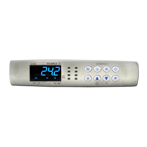
The instrument is equipped with 7 programme keys, a 4-digit
display and 9 LED signals, in addition to an internal buzzer that
is the sound system for alarms. Other important characteristics
of the instrument are: programme parameters protection using
personalised password, Keyboard lock function, switching on
and off (stand-by) of the instrument using the front keys or the
THE
digital input,
device, memorising of two sets of temperature regulations that
can be switched and the possibility of power supply in the
range 100 ... 240 VAC.
PROTECTION
COMPACT
is
a
digital
configuration of parameters via the KEY USB
FUNCTION
AND
controller
with
Advertisement
Table of Contents

Subscribe to Our Youtube Channel
Related Manuals for Osaka COMPACT


Summary of Contents for Osaka COMPACT
- Page 1 ACTIVE SET POINT SELECTION range 100 ... 240 VAC. ON / STAND-BY FUNCTION INFORMATION ON INSTALLATION AND USE PERMITTED USE – OPERATING INSTRUCTIONS – COMPACT – v.2 – PAG. 1 OSAKA...
-
Page 2: Front Panel Description
(see selection of the active set point). modification. To change it press the UP key to increase the value or DOWN to decrease it. – OPERATING INSTRUCTIONS – COMPACT – v.2 – PAG. 2 OSAKA... -
Page 3: Programming
Furthermore, the input cable of the probe has to be kept 4.12) separate from line voltage wiring. If the input cable of the probe is screened, it has to be connected to the ground with only one side. – OPERATING INSTRUCTIONS – COMPACT – v.2 – PAG. 3 OSAKA... -
Page 4: Electrical Wiring Diagram
After 5 sec. or by press the key UP or DOWN the display come Programming instead “tonE” to any value and “toFE” = OFF the back to normal mode. output in probe error condition will remain switched on. – OPERATING INSTRUCTIONS – COMPACT – v.2 – PAG. 4 OSAKA... -
Page 5: Functions
O u t o f f o f f o f f P t C P t C P t C = 3 : Delay between power on phases. – OPERATING INSTRUCTIONS – COMPACT – v.2 – PAG. 5 OSAKA... -
Page 6: Manual Defrost
(output activated in normal OFF) or in error (E2 o -E2) , the output FAN is activated only conditions and disabled in alarm status). depending on the parameters “FCOF” and “FEdF”. – OPERATING INSTRUCTIONS – COMPACT – v.2 – PAG. 6 OSAKA... -
Page 7: External Alarm
"oAd" after which the alarm is activated to signal that the door has been left open. At the deactivation of maximum alarm digital input the light is switch off. – OPERATING INSTRUCTIONS – COMPACT – v.2 – PAG. 7 OSAKA... -
Page 8: Auxiliary Output
. 1) position both dip switch of KEY USB in the ON mode. 2) connect the device to an instrument COMPACT having the 4.14 - FUNCTIONING OF KEYS “U” AND “DOWN/AUX” same features of the one from which has been downloaded the Two of the instrument keys, in addition to their normal desired configuration, plugging the special connector. -
Page 9: Programmable Parameters Table
HEAt - CooL CooL Par. Description Range Def. Continuous cycle Time OFF ÷ 99.59 Temperature alarms Ab - dE hrs.min Type: Ab = Absolute dE =Relative to Set – OPERATING INSTRUCTIONS – COMPACT – v.2 – PAG. 9 OSAKA... -
Page 10: Problems , Maintenance And Guarantee
Maximum temperature alarm in progress dEF= defrosting ALL / On Minimum temperature alarm in progress FAn= fans Digital input alarm in progress AuS= Auxiliary Door open ALt= Silenceable alarm – OPERATING INSTRUCTIONS – COMPACT – v.2 – PAG. 10 OSAKA... -
Page 11: Instrument Ordering Code
Degree of front panel protection : IP 65 mounted in panel with gasket Pollution situation: 2 Operating temperature: 0 ... 50 °C Operating humidity: 30 ... 95 RH% without condensation Storage temperature: -10 ... +60 °C – OPERATING INSTRUCTIONS – COMPACT – v.2 – PAG. 11 OSAKA... - Page 12 TEdf = 8 ºC final temperature defrost Tdco = 1 min. Dripping time (delay of the compressor) Flt = 5 ºC. Temperature starting fan Fd = 2 min. Drip time + static time (fan OFF) – OPERATING INSTRUCTIONS – COMPACT – v.2 – PAG. 12 OSAKA...
Need help?
Do you have a question about the COMPACT and is the answer not in the manual?
Questions and answers