
Related Manuals for Riken Keiki RM-5000 Series


Summary of Contents for Riken Keiki RM-5000 Series
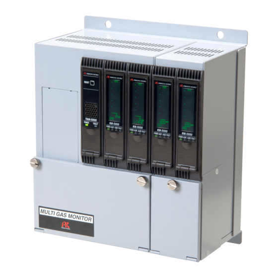
- Page 1 T1E-0740 Indicator/Alarm Unit RM-5000 Series RS-485(Modbus-RTU) Manual for Communication Function...
- Page 2 Thank you for purchasing our indicator/alarm unit RM-5000 series. This manual is a guide to use communication function of RM-5000 series. All persons who use this unit for the first time and who has ever used this unit are requested to read through this manual to understand the contents before use.
-
Page 3: Table Of Contents
2.Register Map ......................... 4 2-1. RM-5000 Modbus Register Map ..................4 2-2. Operation List of Status Data (Address40001) ..............6 3.Communication Specification ....................7 3-1. RM-5000 series ......................... 7 3-2. Modbus Protocol ....................... 8 4.Appendix ..........................9 4-1. Address Setting Method ....................9 4-2. -
Page 4: Basic Information
Basic Information Basic information to use communication function RS-485(Modbus-RTU) of RM-5000 Setting address You can set Modbus address of RM-5000 to 1-128 The number of the simultaneous connection Max. 127 sets against 1 x master unit Transmission Mode RM-5000 supports RTU mode only although Modbus has ASCII mode (transmitted by ASCII strings) and RTU mode (transmitted by binary transmission). -
Page 5: Register Map
2-1. RM-5000 Modbus Register Map Register Map 2-1. RM-5000 Modbus Register Map RM-5000 Modbus register map address Item Content Bit 0 to 1 = Magnification (0: actual size, 1: one tenth, 2: one hundredths, 3:one thousandth) Bit 2 to 3 = Unit (0: vol%, 1: %LEL, 2: ppm, 3: ppb) Bit 4 = Setting information for double range (1: L side, 0: H side and single range ) Bit 5 = Flag for flow trouble... - Page 6 2-1. RM-5000 Modbus Register Map Address Item Content Signed integer Significant figures of digit which is made to integer. Actual 40017 Digit digit is calculated by multiplying this integer by bit 0 to 1 of address 40001 or 40018. 40018 Decimal Point Position 0: actual size, 1: one tenth, 2: one hundredth, 3: one thousandth 40019...
-
Page 7: Operation List Of Status Data (Address40001)
2-2. Operation List of Status Data (address40001) 2-2. Operation List of Status Data (address40001) S t a t u s 3,2 1,0 Normal ○ ○ ○ ○ ○ ○ ○ ○ ○ ○ ○ ○ - - Measuring Alarm : 1st ○... -
Page 8: Communication Specification
3-1. RM-5000 Series Communication Specification 3-1. RM-5000 Series Contents Specification Electrical specification Based on EIA RS-485 Communication specification 2 wire Half Duplex Synchronization method Asynchronous Connection form 1:N Maximum connectable number 127 ea against 1 x master unit Protocol Modbus-RTU... -
Page 9: Modbus Protocol
3-2. Modbus Protocol 3-2. Modbus Protocol Modbus communication is based on master/slave method, that can communicate with some slaves. Master sends a message to slaves, and slaves send back a response. Message frame of Modbus-RTU mode Address Function Data Error Check 8bit(0 –128) 8bit N*8bit(Depends on the function) -
Page 10: Appendix
4-1. Address Setting Method Appendix 4-1. Address Setting Method Explanation of the keys ① MODE ① MODE key ALM2 ② ② ALM2/▲ key ▲ ③ ALM1/▼ key ALM1 ③ ④ TEST/SET key ▼ ④ TEST Setting procedure ① Move to a maintenance mode by pressing and holding MODE key. (Display : [1-1/ZERO] ) ②...
Need help?
Do you have a question about the RM-5000 Series and is the answer not in the manual?
Questions and answers