Advertisement
Quick Links
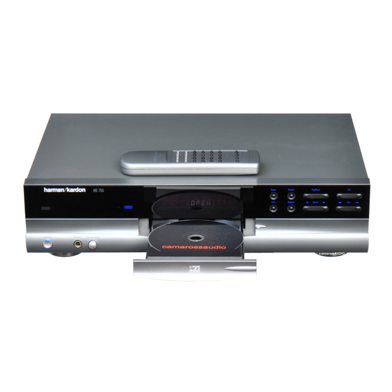
The Harman Kardon
Model HD755 silver
COMPACT DISC PLAYER
Technical Manual
HD755
Standby
1.
LASER BEAM SAFETY PRECAUTIONS ............. 2
2.
CONTROL AND FUNCTIONS ............................. 4
3.
SPECIFICATIONS AND FEATURES ..................... 7
4.
AUDIO CHARACTERISTICS TEST PROCEDURE
.............................................................................. 9
5.
CIRCUIT DESCRIPTION ....................................11
6.
CRITICAL I.C. SPECIFICATION ........................ 15
7.
PART LIST ......................................................... 41
8.
TROUBLE SHOOTING GUIDE .......................... 48
* Harman/ kardon continually strives to improve its products. The HD750 Compact Disc Player design and
specifications are subject to change and may differ from the published specifications and descriptions, but will
always equal or exceed the original specifications unless otherwise stated.
DANGER: Invisible laser radiation when open and interlock failed or defeated.
CONTENTS
AVOID DIRECT EXPOSURE TO BEAM.
9.
BLOCK DIAGRAM ............................................. 54
10. SCHEMATIC DIAGRAMS .................................. 55
11. PCB LAYOUT ..................................................... 59
12. EXPLODED VIEW .............................................. 62
13. PACKING DRAWING ......................................... 63
Parts and Service Office
250 Crossways Park Dr., Woodbury, N.Y. 11797
1112-FL8350 P9603 1200 Printed in Hong Kong
Advertisement

Related Manuals for Harman Kardon HD755


Summary of Contents for Harman Kardon HD755
- Page 1 The Harman Kardon Model HD755 silver COMPACT DISC PLAYER Technical Manual HD755 Standby CONTENTS LASER BEAM SAFETY PRECAUTIONS ..... 2 BLOCK DIAGRAM ..........54 CONTROL AND FUNCTIONS ......4 10. SCHEMATIC DIAGRAMS ........55 SPECIFICATIONS AND FEATURES ..... 7 11. PCB LAYOUT ............. 59 12.
- Page 2 HD755 LASER BEAM SAFETY PRECAUTIONS CLASS 1 LASER PRODUCT CAUTION Invisible laser radiation when the unit is open. Do not stare into beam. CAUTION: USE OF ANY CONTROLS, ADJUSTMENT, OR PROCEDURES OTHER THAN THOSE SPECIFIED HEREIN MAY RESULT IN HAZARDOUS RADIATION EXPOSURE.
- Page 3 HD755 SAFETY PRECAUTIONS This symbol is intended to alert the user to the presence of uninsulated "dangerous voltage" within the product's enclosure that may be of sufficient magnitude to consti- tute a risk of electric shock to persons. This symbol is intended to alert the user to...
- Page 4 HD755 Front Panel Controls Standby Power Switch Open/Close Button Repeat Button Random Button Status Mode Indicator Search Button HDCD Indicator Repeat Button Headphones Jack Skip Button Information Display Headphones Level Control Stop Button Remote Sensor Program Button CD Drawer Play/Pause Button...
- Page 5 HD755 Rear Panel Connections Digital Output Remote Control Input Audio Outputs AC Power Cord Remote Control Output AC Power Cord: Connect this plug to an AC Remote Control Output: Connect this Digital Output: Connect this jack to the coaxial outlet, if the outlet is switch controlled, make...
- Page 6 HD755 Remote Control Functions Display Button Numeric Controls Clear Button Search Buttons Skip Buttons Stop Button Play Button Program Button Pause Button Check Button Time Button Random Button Repeat Button A B Button Power On Power Off Open/ Close Button...
- Page 7 HD755 HD750 Preliminary Production Specification Version 0.1 GENERAL INFORMATION < 1. Power Consumption Operating 18W; Standby <5W 2. Power Super 230V AC 50Hz 3. Dimensions 440 x 130 x 386mm 4. Product Outlook Refer to attached diagram 5. Remote Unit harman/kardon remote code 6.
- Page 8 HD755 HD750 Preliminary Production Specification Test Disc Specification Typical Limit Black Dot TCD 725B 1000um 600um Interruption MCD-131 900um 600um Finger print 75um 65um Vertical Deviation MCD-151 0.92mm 0.92mm Eccentricity TCD 712 140um 140um 8cm test disc TCD 783 Last Track...
- Page 9 HD755 Audio Characteristics Test Procedure Test Equipment 1. 3346 CD Player Evaluating Filter x 2 (NF Electronic Instrument) 2. VP7722 Panasonic Audio Analyzer 3. Sony YEDS18 Test CD disc Procedure Equipment Setup 1. The audio output of the CD player under test is connected to the CD filter L &...
- Page 10 HD755 Signal to Noise Ratio 1. Set the mode of the filter to ‘ S/N’ mode 2. Play track 2 of the test disc 3. The unit of the audio analyzer is set to dB mode 4. Press the S/N key on the control panel of the audio analyzer 5.
- Page 11 HD755 FUNCTION DESCRIPTION Tracking System To Focus System REF1 REF2 Subtraction GCTRL TBAL GCTRL TEOUT TBAL PDIC The tracking error output of E and F is given to Pin 25 (TEOUT). C8 is required for oscillation-proof. R10 is chosen such that TEOUT of Pin 25 become 1.4Vp-p.
- Page 12 HD755 Focus System Subtraction GCTRL FBAL GCTRL PDIC FEOUT FBAL The focus error output of A, B, C and D are given to Pin 27. C4 is required for oscillation- proof. R7 is set such that FEOUT of Pin 27 becomes 1.46 Vp-p.
- Page 13 HD755 RF, EQ, AGC NRFDET RFOUT DETECTION DETECTION GCTRL GCTRL The signals A, B, C and D input from PDIC are composed into the RF signal by the RF Addition Amp, then output from RFOUT of Pin 5. This Amp is designed so that RFOUT is about 0.5 Vp-p for normal CD disc (about 0.4 Vp-p for CDR and 0.12 Vp-p for CDRW).
- Page 14 HD755 LDON LASER UNIT 170mV The laser diode has large negative temperature characteristic in its optical output when driven with a constant current on laser diode. Therefore, the output on processing monitor photo diode, must be a controlled current for getting regular output power, thus the APC (Auto Power Control) circuit is composed.
- Page 15 HD755 MN662790RSA1 Signal Processing LSI for CD Players Overview The MN662790RSA is a CD signal processing LSI that, (Audio circuits) on a single chip, combines optics servos for the CD player Digital filter using 8-fold oversampling (focus, tracking, and traverse servos), digital signal...
- Page 16 HD755 MN662790RAS1 Pin Assignment BYTCK/TVSTOP LDON CLDCK FCLK RFDET IPFLAG TRCRS FLAG CLVS VDET RFENV DEMPH FLAG6/RESY IOSEL TBAL TEST FBAL OUTL OUTR KICK RSEL CSEL PSEL MSEL SSEL (TOP VIEW) QFS080-P-1414...
- Page 17 HD755 MN662790RAS1 Block Diagram OUTR LRCKIN/MSEL BCLKIN/SSEL SRDATEIN/PSEL OUTL IOSEL CLVS BLKCK CLDCK FLAG SBCK IPFLAG SUBC DEMPH FLAG6/RESY SSEL SQCK SUBQ PLLF LRCK PLLF2 SRDATA DSLF BCLK DMUTE RSEL PSEL KICK MCLK BYTCK/TRVSTOP MDATA CK384/EFM VCOF2 VCOF TBAL FBAL...
- Page 18 HD755 MN662790RAS1 Pin Descriptions Pin No. Symbol Function Description BCLK SRDATA bit clock output. LRCK Left/right channel discrimination signal output. SRDATA Serial data output. Power supply for digital circuits. Ground for digital circuits. Digital audio interface output signal. MCLK Microcomputer command clock input. (Data is latched at rising edge.) MDATA Microcomputer command data input.
- Page 19 HD755 MN662790RAS1 Pin Descriptions (continued) Pin No. Symbol Function Description Tracking error signal input. (analog input) RFENV RF envelope signal input. (analog input) VDET Vibration detection signal input. "H" level: vibration detected. Offtrack signal input. "H" level: offtrack. TRCRS Track cross signal input.
- Page 20 HD755 MN662790RAS1 Pin Descriptions (continued) Pin No. Symbol Function Description CLVS Spindle servo phase synchronization signal output. "H" level: CLV. "L" level: rough servo. During default operation, subcode CRC check result output. "H" level: OK. "L" level: no good. During command execution, pulse output for external track counter.
- Page 21 0 H D755 AN8849SB Head amplifier IC for CD-ROM drive (for 24 times speed or more) Overview Unit: mm The AN8849SB is a head amplifier IC for +0.10 15.2±0.3 –0.05 digital servo. It can configure an efficient CD-ROM system in combination with the MN662752, and allows a full-automatic adjustment of tracking bal- ance-gain-offset and focus balance-gain-offset with fewer external parts.
- Page 22 HD755 AN8849SB Block Diagram 3TOUT LDON GCTRL FBAL CROSS NRFDET CCRS CAGC TEOUT TBAL EQSW RFOUT...
- Page 23 HD755 AN8849SB Pin Descriptions Pin No. Description Pin No. Description APC amp. input pin GND pin APC amp. output pin APC & masking control pin RF addition amp. inverted input pin output pin REF1 Power supply pin 1 CROSS output pin RF addition amp.
- Page 24 HD755 AN8849SB = 25°C Electrical Characteristics at T Parameter Symbol Conditions Unit = 5 V, V = 3.3 V Current consumption with no load 1 28.4 40.6 52.8 TOTAL1 +0.75 V EQSW REF2 = 5 V, V = 3.3 V Current consumption with no load 2 1.20...
- Page 25 HD755 AN8849SB = 25°C (continude) Electrical Characteristics at T Parameter Symbol Conditions Unit Tracking error amp. (continued) = 5 V, V = 3.3 V −8.35 −6.35 −4.35 Tracking error amp. +0.5 V balance relative output 2−H REF2 = 5 V, V = 3.3 V...
- Page 26 HD755 AN8849SB = 25°C (continued) Electrical Characteristics at T Parameter Symbol Conditions Unit NRF detection f = 500 kHz, V − 0.75 V NRF det. detection level 137 mV[p-p] RDA1 REF2 f = 500 kHz, V − 0.75 V ...
- Page 27 HD755 AN8814SB 4-channel driver IC for optical disk drive Overview Unit: mm The AN8814SB is a BTL system 4-channel 18.4±0.2 (5.15) driver and is encapsulated in the SMD package (4.8) which excels in heat radiation characteristic. (1.315) Features • Wide output dynamic range regardless of refer- ence voltage of the system •...
- Page 28 HD755 AN8814SB Pin Descriptions Pin No. Description Pin No. Description Motor driver-2 reverse rotation output pin Base control pin for an external transistor of 3.3 V regulator Motor driver-2 forward rotation output pin 3.3 V regulator output monitor pin Motor driver-1 reverse rotation output pin N.C.
- Page 29 HD755 AN8814SB = 25°C Electrical Characteristics at T Parameter Symbol Conditions Unit = 5 V Current consumption with no load Motor driver 1 to motor driver 4 = 5 V, V = 0 V, −10 Input offset voltage = 8 kΩ, R = 10 kΩ...
- Page 30 HD755 AN8814SB = 25°C (continued) Electrical Characteristics at T • Design reference data Note) The characteristics listed below are theoretical values based on the IC design and are not guaranteed. Parameter Symbol Conditions Unit Thermal protection circuit °C...
- Page 31 HD755 ® ® PCM1732 For most current data sheet and other product information, visit www.burr-brown.com 24-Bit, 96kHz, Stereo Audio DIGITAL-TO-ANALOG CONVERTER ® With HDCD Decoder FEATURES DESCRIPTION ENHANCED MULTI-LEVEL ∆Σ DAC The PCM1732 is designed for mid- to high-grade digital audio applications which achieve 96kHz sam-...
- Page 32 HD755 SPECIFICATIONS 24-Bit Data Performance All specifications at +25°C, +V = +V = +5V, f = 44.1kHz, and SYSCLK = 384f , unless otherwise noted. PCM1732 PARAMETER CONDITIONS UNITS RESOLUTION Bits DATA FORMAT Audio Data Interface Format Standard/I Data Bit Length...
- Page 33 HD755 SPECIFICATIONS 16-Bit Data Performance All specifications at +25°C, +V = +V = +5V, f = 44.1kHz, and SYSCLK = 384f , unless otherwise noted. For discussion of HDCD scaling options, see the Applications Considerations section of this data sheet.
- Page 34 HD755 PIN CONFIGURATION PIN ASSIGNMENTS Top View SO-28 NAME DESCRIPTION LRCIN Left and Right Clock Input. This clock is equal to the sampling rate, f Serial Audio Data Input LRCIN ML/I BCKIN Bit Clock Input for Serial Audio Data CLKO Buffered System Clock Output.
- Page 35 HD755 MCU Pin Arrangement and Functions Pin Arrangement VFD.DO MCLK VFD.DI MDATA VFD.CLK VFD.LAT SENSE FLOCK TLOCK SQCK REMOTE SUBQ DMUTE STAT XRST PUSW CDRW Figure 1.2 Pin Arrangement...
- Page 36 HD755 Internal Block Diagram Figure 1.1 shows a block diagram. H8/300L Data bus (lower) /FTID /FTIC /FTIB /FTIA /FTOB /FTOA /TMOW /FTCI /PWM /IRQ /IRQ /IRQ /TRGV /SCK /TMOV Timer A SCI1 /RXD /TMCIV /TXD /TMRIV Timer B1 SCI3 /SCK...
- Page 37 HD755 Pin Functions Pin Name Description No connection No connection AVSS Connected 0V TEST Connected 0V No connection Connected 5V MCU ground line; connected to 0V OSC1 10MHz crystal input OSC2 10MHz crystal input MCU reset line; 0V = reset; 5V = normal operation...
- Page 38 HD755 AMUTE System mute control; 0V = mute No connection No connection No connection No connection No connection VFD.DO Display driver status serial data VFD.DI Display driver command serial data VFD.CLK Display driver command serial clock VFD.LAT Display driver command serial latch...
- Page 39 HD755 PNP/NPN Epitaxial Planar Silicon Transistors 2SA1391/2SC3382 Low Noise AF Amp Applications Features Package Dimensions · Adoption of FBET process. unit:mm · AF amp. 2003A · Low-noise use. [2SA1391/2SC3382] Noise Test Circuit JEDEC : TO-92 B : Base ( ) : 2SA1391...
- Page 40 HD755...
- Page 41 HD755 HD750 ELECTRICAL PARTLIST MAINBOARD ASSEMBLY Reference Part Number Description Quality 9475-001000-011 HD750 MAIN BOARD ASSY REV A Resistor 1001-000314-020 CARBON FILM RESISTOR 10 OHM 1/4W +-5% AXIAL TAPE 1001-000316-020 CARBON FILM RESISTOR 10 OHM 1/6W +-5% AXIAL TAPE R41, R60, R61, R62, R76, R77,...
- Page 42 HD755 R38, R103 1019-103018-020 METAL FILM RESISTOR 91K OHM 1/8W +-1% AXIAL TAPE Capacitor C172 1100-101043-000 CERAMIC CAP. 100PF/50V +-10% C51, C61 1100-102043-000 CERAMIC CAP. 1000PF/50V +-10% 1100-103043-000 CERAMIC CAP. 0.01uF/50V +-10% C2,C3,C5,C14,C15,C18,C23, 1100-104044-000 CERAMIC CAP. 0.1uF/50V +-20% C24,C27,C28,C34,C42,C48,C53, C54,C55,C57,C59,C63,C65,C73,...
- Page 43 HD755 1301-928000-100 TRANSISTOR PNP KSA928A TO-92 SAMSUNG Q25,Q32 1301-933000-100 TRANSISTOR PNP 2SA933 TO92 Q17, Q26 1302-246000-100 TRANSISTOR FET 2SK246GR TO92 Bridge, Diode, Zener IC7, IC8 1401-101000-000 BRIDGE RECTIFIER DB101 50V 1A UL D2, D3, D4, D5 1401-140040-000 DIODE RECTIFIER 1N4004...
- Page 44 HD755 C413, C414 1100-102044-000 CERAMIC CAP. 1000PF/50V +-20% 1100-103043-000 CERAMIC CAP. 0.01uF/50V +-10% C410, C412 1100-103044-000 CERAMIC CAP. 0.01UF/50V +-20% C407, C408 1101-473062-000 POLYESTER/MYLAR CAP. 0.047UF/100V +-5% C409, C411 1102-101024-000 ELECT. CAP. 100UF/25V +-20% C415, C417 1102-471014-000 ELECT. CAP. 470uF/16V +-20% 8X12MM...
- Page 45 TOROID COILS 'T31X19X7.5MM' 4032-100155-000 SOLDER PLATE 10015-5 YUET CHUNG 4081-000000-008 INSULATION SHEET PVC 50X15X0.5MM (HD750) 9475-001000-012 HD755 MAIN BOARD ASSY REV C 9692-006002-161 PU92TL-216 W/SONY 213CCM REV A 4875-510260-001 HD750 FRONT PANEL ASSY REV A 9475-001000-021 HD750 HEADPHONE BOARD ASSY REV A...
- Page 46 HD755 HD750 CD LOADER MECHANISM PARTLIST Part Number Description Quality 9692-006002-161 PU92TL-216 W/SONY 213CCM REV A 2300-005010-000 RIGHT ANGLE CONN WAFER 5PIN 2mmP 2411-010120-029 LEAF SWITCH MSW-1731 CVCE 3009-213000-000 SONY CD MECHANISM 213CCM 4892-050700-012 PU92TL LOADING PCB REV B 6090-050010-000...
- Page 47 HD755 6002-000019-000-01 HARMAN KARDON HD750 REMOTE INLAY 28KEYS 6600-010156-001 CONTACT BATTERY COMMON 6600-010157-000 RT02-S002 CONTACT BATTERY POS 6600-010158-000 RT02-S003 CONTACT BATTERY NEG 6600-070116-000 KEY PAD 28 KEYS FOR RT-02 7002-008002-021 SCREW M2X8 P TYPE P/H BLK REMOTE CONTROL BOARD ASSEMBLY...
- Page 48 HD755...
- Page 49 HD755...
- Page 50 HD755...
- Page 51 HD755...
- Page 52 HD755...
- Page 53 HD755...
- Page 54 AN4801SB...
- Page 55 MAINBOARD HD755 AN4801SB...
- Page 57 HD755...
- Page 58 HD755 REMOTE UNIT...
- Page 59 HD755...
- Page 60 HD755 HEADPHONES PCB POWER SWITCH PCB...
- Page 63 HD755...
- Page 64 9475-001000-012 Z-000A01...
- Page 65 5100-755000-000 9805-755000-001 5013-750001-000-03 HD755...
Need help?
Do you have a question about the HD755 and is the answer not in the manual?
Questions and answers