Table of Contents
Advertisement
Quick Links
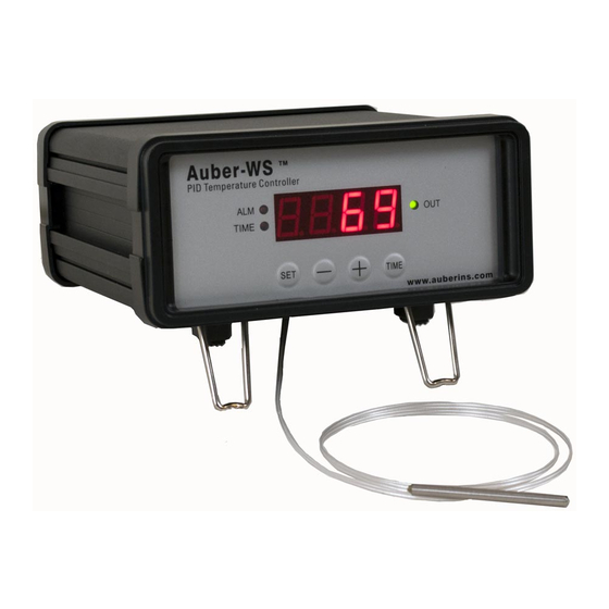
Precision PID Temperature Controller
Introduction
Thank you for shopping the Auber WS series temperature controller. We sincerely appreciate
your decision and trust that our controller will meet your expectations in both the quality of the
result and the value of the product. While we are delighted that you may be anxious to operate
the controller, please still spend a few minutes reading through this manual because this will
serve to enhance your experience in the months and years ahead. In particular, we urge you to
read through the safety warnings below. Although this plug-and-play controller is very easy to
use, the process involves high temperature and high wattage appliances and your safety is
paramount.
•
This controller is designed only to be used with limited-power device and paring thermal
cutoff protection such as a thermostat or thermal.
•
Do not place any objects on the top of controller surface because that may prevent
venting excess heat during its operation.
•
The controller can handle a maximum current up to 15 Ampere. For 120 VAC in US or
Canada, this limits the heater power to 1800 watts. Due to its compact size and the
splash proof design for kitchen applications, the controller has a limited ability to dissipate
the heat generated by the internal solid state relay during the initial heat up. The initial full
power heat up process cannot be more than 90 minutes. If you system need take longer
time to warm up, please read Appendix 1 "Managing the heat generated by the
controller"
Operation Instruction Manual
WS-1510ELPM
Version 1.5 (Oct, 2019)
Auber Instruments
5755 North Point Parkway, Suite 99
Alpharetta, GA 30022
770-569-8420
www.auberins.com
SAFETY WARNINGS
1
Advertisement
Table of Contents

Related Manuals for Auber WS Series


Summary of Contents for Auber WS Series
- Page 1 Introduction Thank you for shopping the Auber WS series temperature controller. We sincerely appreciate your decision and trust that our controller will meet your expectations in both the quality of the result and the value of the product. While we are delighted that you may be anxious to operate the controller, please still spend a few minutes reading through this manual because this will serve to enhance your experience in the months and years ahead.
-
Page 2: Specifications
Using it to control a not recommended device can be dangerous and even cause fire. Auber Instruments is not liable for damages caused by misuse of the controller. If you are not sure the controller can be used, please contact Auber Instruments before usage. - Page 3 Operating Instructions 1. Controller Figure 1. Front Panel. The front panel of the controller is shown in Figure 1. The function of each item is described below: (1) Parameter Window (LED) - For displaying temperature values and controller's system parameters. (2) Output status indicator - In normal mode, this LED indicates the heater status.
-
Page 4: Connecting The Controller
(7) Alarm indicator - Lit when the alarm is on. (8) Timer status indicator – Lit when Time key is pressed. (9) Editing indicator – A dot at the lower right corner. When the dot flashing, the value is editable; pressing the “+” or “-“ key to change the value. The layout of the controller back panel is shown in Figure 2. - Page 5 A schematic wiring diagram of the controller and the device to be controlled is shown in Figure 3. The connection of the controller with the device and the sensor should be done with the following steps: • Plug the sensor into the sensor port on the back of the controller. •...
- Page 6 Figure 4. How to remove the sensor. 3. Programming the temperature profile. A total of 6 steps can be programmed for this controller. Each step contains the temperature (C-X) and time duration (t-X) setting. They are represented by the symbol C-X and t-X, where “X” is the step number (e.g.
- Page 7 Figure 5. Temperature profile programming flow chart. Here is the one step heating program. The temperature profile is programmed to start at 150 °F for 600 minutes of heating. Table 1. Initial program setting. Temp Time Step # Step # (min)
-
Page 8: System Configuration Parameters
4. Checking the current step and the time The user can check step number, total running time, and the time in the current step using the “Time” or “+” key. Please see the flow chart in Figure 7. Figure 7. How to check current step and the time. At normal operating mode, press the “+”... -
Page 9: Symbol Display
Table 2. List of control parameters and its initial settings under code 166. Symbol Display Description Range Initial Proportional Band 0-9999 Integral Const. (Sec.) 0-9999 Derivative Const. (Sec.) 0-9999 Auto-tune 0=off, 1=on Cycle Rate (Sec.) 2-9999 Details about each parameter •... - Page 10 • d, Derivative time. The unit is in seconds. Derivative action contributes the output power based on the rate of temperature change. Derivative action can be used to minimize the temperature overshoot by responding its rate of change. The larger the number is, the faster the action will be, e.g.
- Page 11 will show the “I “ for a second and its I setting value next, use the same “P” setting procedure to set the I value. When finished, press the SET again to confirm the change. The display will show the “d” for a second and its value next. Use the same “P” setting procedure to set the d value. When finished, press the SET again to confirm the change.
- Page 12 Temperature Unit °C or °F °F Mode Selection PID, Cool, Heat Hysteresis Band 0-9999 Anti-short Cycle 0-200 Delay (only for cooling mode) Details about each parameter. • SC: Calibration offset. The parameter is used to make the input offset to compensate for the error produced by sensor.
- Page 13 • Hy: Hysteresis band (or dead band). This parameter is valid only on/off control mode. In the on/off heating mode, the controller will stop sending power to the heater when temperature T is above the set value (SV), and start sending power again to the heater if T drops below (SV-Hy).
- Page 14 displays “LoCK”. Release the SET. The display will show “0”. Use “+” and “-” keys to adjust the display to 155 (another pass code) and press SET. The display will show the parameter for a second and then its value, use “+” and “-” keys to change the setting. When finished, press the SET again to confirm the change.
- Page 15 Lock 3 sec Figure 10. Parameter setup flow chart under (code 188). 6. Save and recall recipes This controller can save up to 8 pieces of smoking recipe (programs). Each recipe file can have up to 6 steps (C-1 to C-6). For convenience, we have pre-named these 8 pieces of recipe files as B1 (beef), B2, C1 (chicken), C2, F1 (fish), F2, P1 (pork), and P2.
- Page 16 lock saue Figure 11. Flow chart of saving a recipe. 6.2 Recall a recipe. WARNING: You current program will be overwritten by the selected recipe. Please write it down somewhere if it is important to you. To recall a recipe, press and hold SET key for 3 seconds until the Parameter Window displays “LoCK”.
-
Page 17: Single-Step Mode
lock Figure 12. Flow chart of recalling a recipe. 7. Single-step mode In this mode, the controller will hold temperature at one set value (C-1) continuously as long as the controller is powered on. Even if the controller is powered off and turned on again, it will resume working in this mode. - Page 18 Figure 13. Single-step mode flow chart. In single-step mode, the save and recall function (Section 7) still work. But the change can only be applied to C-1, i.e., you can only store your current set temperature to the C-1 in a selected recipe, or recall the C-1 temperature from a selected recipe to the current set temperature.
-
Page 19: Advanced Examples
To store current program back to recipe b2, long press SET, set LoCK=2, choose b2, press set to confirm and exit. Now your current program is stored as recipe b2. Recall your recipe to current program (Single-step Mode) Before you input your set temperature, check the PrG = off (accessed by LoCK code “3”). Long press SET, set LoCK=1, choose b2, press set to confirm and exit. -
Page 20: Digital Filter Function
Copyright 2007-2017, Auber Instruments All Rights Reserved. No part of this manual shall be copied, reproduced, or transmitted in any way without the prior, written consent of Auber Instruments. Auber Instruments retains the exclusive rights to all information included in this document. - Page 21 Appendix 1 Managing the heat generated by the controller The heat dissipation of the controller is directly related to the electric current drawing power of the heater. If your cooker consumes less than 10 ampere of current or your pot is less than 5 gal (19 liters), you do not need to worry about the heat generated by the controller.
- Page 22 Copyright 2007-2019, Auber Instruments All Rights Reserved. No part of this manual shall be copied, reproduced, or transmitted in any way without the prior, written consent of Auber Instruments. Auber Instruments retains the exclusive rights to all information included in this document.
Need help?
Do you have a question about the WS Series and is the answer not in the manual?
Questions and answers