Table of Contents
Advertisement
INSTALLATION, OPERATION, AND SERVICE MANUAL
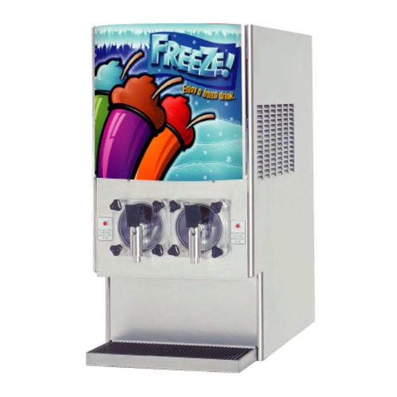
FROZEN BEVERAGE DISPENSER
DIMENSIONS
Width
Depth
Height (Standard Countertop Unit)
Height (Optional Roll Around Unit/Stand)
WEIGHT
Shipping
Empty
Operational
WATER REQUIREMENTS
Minimum flowing pressure
Maximum static pressure
CARBON DIOXIDE (CO
Minimum pressure
Maximum pressure
The information contained in this document is subject to change without notice.
FBD MAKES NO WARRANTY OF ANY KIND WITH REGARD TO THIS MATERIAL, INCLUDING, BUT NOT LIMIT-
ED TO, THE IMPLIED WARRANTIES OF MERCHANTABILITY AND FITNESS FOR A PARTICULAR
PURPOSE. FBD shall not be liable for errors contained herein or for incidental consequential damages in connection with the
furnishings, performance, or use of this material.
This document contains proprietary information which is protected by copyright. All rights reserved.
THIS DOCUMENT CONTAINS IMPORTANT INFORMATION
This manual must be read and understood before the installation and operation of this dispenser.
This manual supersedes FBD Manual 24-0276-0003, dated 01/31/05.
• FBD TECHNICAL SUPPORT • 1-866-323-2777 • TECHNICAL SUPPORT FAX 1-210-637-2832
FOR THE
MODEL FBD550
SPECIFICATIONS
) REQUIREMENTS
2
© Copyright 2006 by FBD, all rights reserved.
FBD Partnership, LP
• P.O. BOX 18597. • SAN ANTONIO, TX 78218 USA •
• 210-637-2800 • FAX 210-637-2844 • www.fbdfrozen.com •
17.0 inches
(432 mm)
32.3 inches
(820 mm)
34.0 inches
(864 mm)
68.0 inches (1727 mm)
395 pounds (179.2 kg)
318 pounds (144.2 kg)
345 pounds (156.5 kg)
30 PSIG
(207.0 KPa)
70 PSIG
(483.0 KPa)
70 PSIG
(483.0 KPa)
75 PSIG
(517.5 KPa)
NOTICE:
Revision:
FBD Part Number: 24-0276-0003
Check out the FBD web site:
www.fbdfrozen.com
10-25-06
Advertisement
Table of Contents

Related Manuals for FBD FBD550


Summary of Contents for FBD FBD550
- Page 1 FBD MAKES NO WARRANTY OF ANY KIND WITH REGARD TO THIS MATERIAL, INCLUDING, BUT NOT LIMIT- ED TO, THE IMPLIED WARRANTIES OF MERCHANTABILITY AND FITNESS FOR A PARTICULAR PURPOSE. FBD shall not be liable for errors contained herein or for incidental consequential damages in connection with the furnishings, performance, or use of this material.
-
Page 2: Table Of Contents
DAILY CLEANING OF THE UNIT ....................14 SANITIZING THE SYRUP SYSTEMS .....................14 9. BASICS OF OPERATION .........................15 MAKING ADJUSTMENTS TO THE FBD550 ...................15 10. CHANGING FACTORY SET “LEVEL CONTROL” ..................16 10.1 BEFORE CHANGING “LEVEL CONTROL” SETTINGS..............16 10.2 DRINK TOO HARD AND COLD.......................17 10.3 DRINK TOO LIQUID ........................17... -
Page 3: Safety Precautions
HEADER BLOCK SUB ASSEMBLY ..................53-54 14.18 FRONT ASSEMBLY.........................55-56 SAFETY PRECAUTIONS We at FBD are concerned about your safety. Please carefully read the following precautions before working with the FBD550 unit. This will familiarize you with proper equipment handling techniques. LIFTING •... -
Page 4: Preparing The Location
1. PREPARING THE LOCATION 12 INCHES 2 INCHES 2 INCHES LOCATION REQUIREMENTS A. The operational FBD550 countertop unit weighs 345 pounds (156.5 kg) and requires a sturdy, level surface for placement. When selecting a counter location, ensure the counter will support the unit weight plus the weight of any additional equipment placed near it. -
Page 5: Roll Around Cart
drip tray). If permanently mounting the unit to a countertop, use the information in Section 14.1 to mark and drill the four (4) mounting holes in the countertop. B. With the side panels removed, lift unit by the frame cross bracing and place unit on the counter. C. -
Page 6: Connecting Water, Co , And Syrup Supplies
5. CONNECTING WATER, CO , AND SYRUP SUPPLIES WATER SUPPLY IMPORTANT A WATER PUMP AND WATER REGULATOR ARE INSTALLED IN THE BASE OF THE MACHINE. A WATER FILTER SHOULD BE INSTALLED IN THE WATER LINE BEFORE BEING CONNECTED TO THE MACHINE. FLUSH THE FILTER WITH SEVERAL GALLONS (12-15 LITERS) OF WATER PRIOR TO USE TO INSURE BLACK CARBON "FINES"... -
Page 7: Starting The Unit
BIB SUPPLY A. Fabricate two (2) 1/4 inch supply lines for connecting the unit to the syrup pumps. B. Connect the lines to the bulkhead fittings labeled "SYRUP 1 LEFT" and "SYRUP 2 RIGHT" located at the rear of the unit (see Figure 5.2). C. -
Page 8: Brixing
BRIXING A. With the unit powered up, press both of the "OFF" buttons on the display to ensure the unit is in the OFF state. CAUTION CHECK ALL SUPPLY LINES TO ENSURE THAT THEY ARE CONNECTED TO THE CORRECT FITTINGS. IF LINES ARE NOT CONNECTED PROPERLY, COMPONENTS WILL BE DAMAGED. -
Page 9: Filling The Chamber
FILLING THE CHAMBER Sample Valve A. Access "CO SOL" by going to the "SERVICE MENU\MANUAL ON/OFF" section of the service menu. B. Displace the air in the chamber with by activating the CO solenoid. 1. Pull and hold the relief ring until the Sample escaping, rushing air sound almost stops;... -
Page 10: Critical Regulator And Flow Control Settings
CRITICAL REGULATOR AND FLOW CONTROL SETTINGS SET ALL PRESSURES USING THE LCD READOUTS ON THE UNIT - NOT BY THE GAUGES ON THE REGULATORS! PRIMARY REGULATOR The CO Primary Regulator MUST BE SET TO 70-72 PSIG (482.6 TO 496.4 KPa). SECONDARY REGULATOR The CO Secondary Regulator SHOULD BE SET AT 28-32 PSI (Secondary Regulator) (206.8 TO 220.8 KPa) STATIC PRESSURE. - Page 11 BEATER The BEATER button activates the beaters inside the freezing chambers. The beaters can be activated to mix the slurry. NOTE: The beaters start automatically when the RUN or DEF buttons are pressed. The DEF button allows the user to manually defrost chamber. Because the unit automatically defrosts during the day, it is not necessary to defrost manually.
- Page 12 optimize the operation of the machine. Incorrect settings at this level could prevent the machine from operating properly or cause damage to the unit. Included in this level are various accumulated totals and diagnostic tools that help the technician evaluate problems. NOTE To access the Service Menu, press the FWD button on the control panel until “SERVICE MENU”...
- Page 13 SELECT Figure 7.3...
-
Page 14: Machine Access
MACHINE ACCESS (SEE FIGURE 7.2) A. Machine Operator Display Mode Display Description Preset Value 1. VERSION Shows current version of the software installed. 2. TIME Used to set the time of day. The machine uses a 24 hour format (military time) clock. The clock has a battery backup which maintains correct time even if not plugged into electrical power. -
Page 15: Machine Settings
MACHINE SETTINGS These settings are preset by the machine. DO NOT change unless there is a problem with drink quality. Mode L Side Settings Level Control = 3 The higher the value, the higher the product level in the chamber. R Side Settings The lower the value, the lower the product level in the chamber. -
Page 16: Readouts
If other equipment is being cleaned, follow the guidelines established for that equipment. A. FBD equipment (new or reconditioned) is shipped from the factory, cleaned and sanitized in accordance with NSF guidelines. After installation is complete, the operator of the equipment must provide continuous maintenance as required by this manual and/or state and local health department guidelines to ensure proper operation and sanitation requirements are maintained. -
Page 17: Required Cleaning Equipment
110 to 115°F (44 to 46°C). Stir the solution until sanitizing agent has completely dissolved. F. Disconnect all BIB connectors from syrup boxes, then install BIB Adapters (FBD PN 05-0249) onto BIB connectors. G. Turn off the water at source, and then press down on sample valve until water is purged from system. -
Page 18: Basics Of Operation
MAKING ADJUSTMENTS TO THE FBD550 A. In order to produce a consistent, quality beverage with the FBD550 Frozen Beverage Machine, there are a few critical settings that must be maintained. These settings are preset when you receive the machine from the factory, but, due to variations that occur (e.g., in operating... -
Page 19: Changing Factory Set "Level Control
c. The default value set at the factory is 3. This setting should produce an excellent quality product. (See Section 10 for instructions on changing settings.) 3. Regulated CO Injection Pressure a. The CO injection pressure is set by adjusting the secondary regulator, located behind the access panel below the control panel in the front of the machine. -
Page 20: Drink Too Hard And Cold
secondary regulator inside the unit is properly set to 28-32 PSIG (206.8 to 220.8 KPa), the chamber pressure will be “set” automatically. F. After the machine is installed and each chamber is properly filled, press the “DEF” button on the control panel to allow the machine to automatically “baseline”. -
Page 21: Changing Factory Thaw And Freeze Settings
2. Press the “SELECT” button, “L Side Settings” displays. If “R Side Setting” is desired, press “Forward”. 3. Press “SELECT” and “Level Control” displays. 4. Press the “SELECT” button and the default setting of “3” begins to flash. The level is raised by pressing the “FWD”... -
Page 22: Critical Information
A. Changing the THAW-FREEZE for LEFT SIDE and RIGHT SIDE 1. Access the service level by pressing the “FWD” button on the control panel until the “SERVICE MENU” displays. Press the unmarked button on the right side of the panel, “MACHINE SETTINGS”... -
Page 23: Troubleshooting Guide
13. TROUBLESHOOTING GUIDE The following information is a listing of the most common problems that could keep the FBD550 Dispenser from operating properly. Contact the factory for details, when necessary. TROUBLE CAUSE REMEDY MECHANICAL 13.1 Chamber will not fill. A. “Fill“ off. - Page 24 TROUBLE CAUSE REMEDY (Item 13.3 continued from previous page.) E. CO or water can’t keep up E. Reroute water or CO lines to with unit demand. maximize supply pressure. Install Water Booster if necessary. F. Excessive pressure drops F. Observe “Syrup Press” readouts in syrup lines.
-
Page 25: Electrical
TROUBLE CAUSE REMEDY 13.6 Brix sample valve leaks. A. Damaged or failed o-rings A. Turn off CO , water and disconnect on valve. syrup. Depressurize by pressing sample valve. Remove C-clip from bottom of sample valve. Remove sample valve shaft, change o-rings and reinstall. -
Page 26: Electronic Controls
TROUBLE CAUSE REMEDY (Item 13.11 continued from previous page.) C. Voltage Offset transformer C. Check Voltage Offset Transformer problem. for 220 VAC input/ 24 VAC output. Also check P-18 on upper board for 24VAC. Replace transformer, if necessary. 13.12 Low beater counts. A. -
Page 27: Refrigeration
13 amps) on compressor. Check compressor wiring and terminals. Replace compressor, if necessary. Contact FBD Warranty Dept. before tapping system if unit is under warranty! 13.22 Compressor runs long A. Return temperature not A. Verify that Return Temperature time but won’t freeze dropping. -
Page 28: Drink Quality
2. Test relay board for 24VAC output and 5VDC relay coil input. Replace, if necessary. G. Expansion valve restriction. G. Contact FBD Warranty Dept. before tapping system, if unit is under warranty! Recover refrigerant and remove blockage or replace valve if necessary. - Page 29 TROUBLE CAUSE REMEDY (Item 13.25 continued from previous page.) C. CO solenoid not opening. C. Activate "CO2 Sol" in “Manual On/Off”. Check for 24VAC at coil. Clean solenoid or replace, if necessary. D. CO level in drink too low. D. 1. To affect BOTH chambers, raise "Reg.CO2"...
-
Page 30: Lcd Display Error Messages
TROUBLE CAUSE REMEDY 13.27 Drinks “collapse” or A. Chamber not filled properly. A. Defrost and assure chamber is “fall”. (CO 90% full. Then press "Run". escaping from the B. CO level in drink too high. B. 1. To affect BOTH chambers, drink.) lower "Reg.CO2"... - Page 31 TROUBLE CAUSE REMEDY (Item 13.29 continued from previous page.) G. Secondary regulator pressure G. Insure CO regulator has not creeping up. climbed above preset 30-32 PSIG (206.8-220.8 KPa). H. CO check valve problem. H. Inspect CO check valve. Clean or replace if necessary. 13.30 Max Fill A.
- Page 32 TROUBLE CAUSE REMEDY 13.35 H20 Out A. Unit receiving no water. A. Assure water is turned on. B. Restriction in lines. B. Assure all lines are free of crimps or restrictions. C. Regulator pressures (unit C. Check pressure readouts (H O and water pump) too low or CO ) for 70-72psi.
-
Page 33: Lcd Display Messages
2. Check for poor connection in sensor plug. 3. Replace temperature sensor. LCD DISPLAY MESSAGES FBD550 FROZEN BEVERAGE DISPENSER MESSAGE DESCRIPTION Sleeping Unit in “Sleep” mode. Unit is shut down. Cmpr StDly This delay is before compressor starts. The time period varies from 1 to 30 seconds. -
Page 34: Lcd Display Error Messages
LCD DISPLAY ERROR MESSAGES FBD550 FROZEN BEVERAGE DISPENSER MESSAGE DESCRIPTION DEFPresMax Chamber pressure is above 55 PSIG during defrost only. DEFProdOut Product is out during defrost only. BTR-LO-ERR Low beater percent. Below 450%. BTR-HI-ERR High beater percent. Above 1200%. SYRUP OUT Syrup pressure is below 45 PSIG. -
Page 35: Illustrations, Parts Listings, And Diagrams
14. ILLUSTRATIONS, PART LISTINGS, AND DIAGRAMS 14.1 MOUNTING DIAGRAM This Figure illustrates the locations of threaded mounting holes in the base of the FBD550 machine. 20" EDGE OF MACHINE EDGE OF MACHINE 32.3" 14 7/8" 1 1/16" USE 1/2" DRILL BIT (4 HOLES) 10 1/4"... -
Page 36: Flow Diagram/Schematic
14.2 FLOW DIAGRAM/SCHEMATIC SYRUP SYRUP BRIX ADJUSTER BRIX ADJUSTER 0.25 0.25 0.039 0.039 CO2 INJECT CO2 INJECT EXPANSION EXPANSION CHAMBER CHAMBER (PRESET, RELIEVING) FREEZE FREEZE CHAMBER CHAMBER R SIDE L SIDE PRODUCT DISPENSER PRODUCT DISPENSER LEGEND LEGEND PRODUCT DISPENSER PRODUCT DISPENSER CHECK CHECK VALVE... - Page 37 14.3 WIRING DIAGRAM/50-60HZ SCHEMATIC RV39...
Need help?
Do you have a question about the FBD550 and is the answer not in the manual?
Questions and answers