Table of Contents
Advertisement
Quick Links
BBG-1034-AUD-PRO-DSP
BBG-1034-AUD-PRO-DSP
3G/HD/SD-SDI Standalone Advanced Audio Processor
with DSP Audio Options Support and Full Embed/De-Embed
Product Manual
Cobalt Digital Inc.
2506 Galen Drive
Champaign, IL 61821
Voice 217.344.1243 • Fax 217.344.1245
www.cobaltdigital.com
BBG-1034-AUDPRO-OM (V1.6)
Advertisement
Table of Contents
Troubleshooting

Related Manuals for Cobalt Digital Inc BBG-1034-AUD-PRO-DSP


Summary of Contents for Cobalt Digital Inc BBG-1034-AUD-PRO-DSP
- Page 1 BBG-1034-AUD-PRO-DSP BBG-1034-AUD-PRO-DSP 3G/HD/SD-SDI Standalone Advanced Audio Processor with DSP Audio Options Support and Full Embed/De-Embed Product Manual Cobalt Digital Inc. 2506 Galen Drive Champaign, IL 61821 Voice 217.344.1243 • Fax 217.344.1245 www.cobaltdigital.com BBG-1034-AUDPRO-OM (V1.6)
- Page 2 Furthermore, Cobalt Digital Inc. reserves the right to make changes to any products herein to improve readability, function, or design. Cobalt Digital Inc. does not assume any liability arising out of the application or use of any product or circuit described herein.
-
Page 3: Table Of Contents
Setup/Operating Instructions ......Overview ..........................3-1 BBG-1034-AUD-PRO-DSP Front Panel Display and Menu-Accessed Control ....3-1 Connecting BBG-1034-AUD-PRO-DSP To Your Network..........3-3 Finding a BBG-1034-AUD-PRO-DSP Device in DashBoard ....... - Page 4 BBG-1034-AUD-PRO-DSP Function Menu List and Descriptions ........3-9 Audio DSP Setup Controls .................. 3-10 Input Video Controls ................... 3-24 Output Video Mode Controls ................3-25 Framesync ......................3-26 Scaler ........................3-29 Video Delay Controls ..................3-32 Input Audio Status ....................3-33 Input Audio Routing/Controls ................
-
Page 5: Chapter 1 Introduction
Also provides general information regarding the BBG-1034-AUD-PRO-DSP. Chapter 2, “Installation and Setup” – Provides instructions for • installing the BBG-1034-AUD-PRO-DSP and setting up its network access. Chapter 3, “Setup/Operating Instructions” – Provides overviews • of operating controls and instructions for using the BBG-1034-AUD-PRO-DSP. -
Page 6: Cobalt Reference Guides
UI setups and other topics. Manual Conventions In this manual, display messages and connectors are shown using the exact name shown on the BBG-1034-AUD-PRO-DSP itself. Examples are provided below. Device display messages are shown like this: •... -
Page 7: Warnings, Cautions, And Notes
Symbol (WEEE 2002/96/EC) For product disposal, ensure the following: • Do not dispose of this product as unsorted municipal waste. • Collect this product separately. • Use collection and return systems available to you. BBG-1034-AUDPRO-OM (V1.6) BBG-1034-AUD-PRO-DSP PRODUCT MANUAL... -
Page 8: Safety And Regulatory Summary
This device contains no user serviceable components. Refer servicing to authorized CAUTION personnel. The BBG-1034-AUD-PRO-DSP FPGA is designed for a normal-range operating temperature CAUTION around 85° C core temperature. Operation in severe conditions exceeding this limit for non-sustained usage are within device operating safe parameters, and can be allowed by setting this control to Disable. -
Page 9: Bbg-1034-Aud-Pro-Dsp Functional Description
Note: The BBG-1034-AUD-PRO-DSP DSP base adds support for various DSP audio options. Specific individual DSP user assets (such as loudness pro- cessing, upmixing, and Dolby encoders) are activated for use only when cor- responding option licenses also reside on the device. - Page 10 BBG-1034-AUD-PRO-DSP Functional Description Figure 1-1 BBG-1034-AUD-PRO-DSP Functional Block Diagram BBG-1034-AUD-PRO-DSP PRODUCT MANUAL BBG-1034-AUDPRO-OM (V1.6)
-
Page 11: Video Processor Description
Introduction BBG-1034-AUD-PRO-DSP Functional Description Video Processor Description The BBG-1034-AUD-PRO-DSP video subsystem provides the functions described below. Input Video Select/Quality Check Functions A GUI-based control allows the device to select from up to four 3G/HD/ SD-SDI inputs, and a SD CVBS analog video input. For analog inputs, waveform-based ancillary data is preserved for extraction and usage later in the device processing chain. - Page 12 BBG-1034-AUD-PRO-DSP Functional Description Scaler Function Option provides up/down/cross-conversion to 3G/HD/SD from +UDX multiple SD and 3G/HD video formats and multiple frame rates, and cross-conversion between interlaced and progressive formats, with auto-format detect/down-conversion of SMPTE 424M/292M/259M formats. The scaler function also provides aspect ratio conversion that provides a choice from several standard aspect ratios.
- Page 13 Introduction BBG-1034-AUD-PRO-DSP Functional Description 3G/HD/SD–SDI Ref VITC Frame Reference Waveform SDI VITC Detect/Extract Timecode Proc/Embed Program Video SDI VITC Input Waveform Priority/ Buffer/ ATC_VITC Detect/Extract Select Format Timecode Proc/Embed SDI ATC_VITC Detect/Extract ATC_LTC Timecode SDI ATC_LTC Proc/Embed Detect/Extract Free Run...
-
Page 14: Audio Processor Description
BBG-1034-AUD-PRO-DSP Functional Description Video Quality Events Detect Function Option provides a user interface and an Video Quality Events Event user interface for setting an area of concern across the program raster Triggers which can be monitored for frozen or black video events. Threshold controls... - Page 15 Introduction BBG-1034-AUD-PRO-DSP Functional Description An Input Audio Status display shows the presence and peak level of each input audio channel received by the device. In addition to SDI embedded audio channel sources, analog and coaxial AES inputs are available as input audio choices.
- Page 16 BBG-1034-AUD-PRO-DSP Functional Description Audio Down Mix Function (See Figure 1-4.) The Audio Down Mixer function provides for the selection of any five embedded channels serving as Left ( ), Right ( ), Center ( ), Left Surround ( ), and Right Surround (...
- Page 17 Introduction BBG-1034-AUD-PRO-DSP Functional Description path positioning locates the DSP pipeline to receive Output Mixer • Audio Bus channels and then place the DSP processed output channels directly at the device audio outputs as sources for destination Embedded Output or AES Output channels via the Output Audio Routing/Controls.
- Page 18 +TTS available as a software option for new BBG-1034-AUD-PRO-DSP units. For field upgrade, the unit must be returned to the factory for option installation. interfaces with industry standard Windows Share folder systems to...
-
Page 19: Control And Data Input/Output Interfaces
(either manually or via event-based loading), the GPO is correspondingly also activated. Serial (COMM) Ports The BBG-1034-AUD-PRO-DSP is equipped with two, 3-wire serial ports ). The ports provide for SMPTE COM 1 - Serial Port 1 COM 2 - Serial Port 2... -
Page 20: User Control Interface
Technical Specifications User Control Interface BBG-1034-AUD-PRO-DSP uses an HTML5 internal web server for control/ monitoring communication, which allows control via a web interface with no special or unique application on the client device. Connection to the device to the network media connection is via a standard 10/100/1000 RJ-45 Ethernet connection. - Page 21 Up to (2) balanced using 3-wire removable Phoenix connectors; above) 0 dBFS => +24 dBu AES Audio Inputs (certain models only; Standard: see Part number, nomenclature above) SMPTE 276M Number of Inputs: Up to (8) unbalanced; AES-3id Impedance: 75 Ω 1-17 BBG-1034-AUDPRO-OM (V1.6) BBG-1034-AUD-PRO-DSP PRODUCT MANUAL...
- Page 22 Master delay control; range of -33 msec to +3000 msec. AES Audio Outputs (certain models only; Standard: see Part number, nomenclature above) SMPTE 276M Number of Outputs: Up to (8) unbalanced; AES-3id Impedance: 75 Ω 1-18 BBG-1034-AUD-PRO-DSP PRODUCT MANUAL BBG-1034-AUDPRO-OM (V1.6)
- Page 23 Max V: 30 V Max P: 120 mW GPI Specifications: GPI LO @ Vin < 1.5 V GPI HI @ Vin > 2.3 V Max Vin: 9 V Redundant (or spare) AC power supply BBG-1000-PS 1-19 BBG-1034-AUDPRO-OM (V1.6) BBG-1034-AUD-PRO-DSP PRODUCT MANUAL...
-
Page 24: Warranty And Service Information
(1) year. Cobalt Digital Inc.'s (“Cobalt”) sole obligation under this warranty shall be limited to, at its option, (i) the repair or (ii) replacement of the product, and the determination of whether a defect is covered under this limited warranty shall be made at the sole discretion of Cobalt. -
Page 25: Contact Cobalt Digital Inc
Introduction Contact Cobalt Digital Inc. Contact Cobalt Digital Inc. Feel free to contact our thorough and professional support representatives for any of the following: Name and address of your local dealer • Product information and pricing • Technical support •... - Page 26 This page intentionally blank 1-22 BBG-1034-AUD-PRO-DSP PRODUCT MANUAL BBG-1034-AUDPRO-OM (V1.6)
-
Page 27: Chapter 2 Installation And Setup
• Installing the BBG-1034-AUD-PRO-DSP Note: • Where BBG-1034-AUD-PRO-DSP is to be installed on a mounting plate (or regular table or desk surface) without optional frame Mounting Tray BBG-1000-TRAY, affix four adhesive-backed rubber feet (supplied) to the bottom of BBG-1034-AUD-PRO-DSP in locations marked with stamped “x”. -
Page 28: Bbg-1034-Aud-Pro-Dsp Unit Dimensions
Perform rear panel cable connections as shown in Figure 2-3. Note: • The BBG-1034-AUD-PRO-DSP BNC inputs are internally 75-ohm termi- nated. It is not necessary to terminate unused BNC video inputs or outputs. • External frame sync reference signal (if used) must be terminated if a looping (daisy-chain) connection is not used. - Page 29 2. If BBG-1034 is mounted on flat surface, either rubber feet must be installed, or mounting surface must be open to mate with cooling vents on bottom of BBG-1034 chassis. Figure 2-2 BBG-1034-AUD-PRO-DSP Dimensional Details BBG-1034-AUDPRO-OM (V1.6) BBG-1034-AUD-PRO-DSP PRODUCT MANUAL...
- Page 30 RJ-45 connector (where available) that provides the following: - Multi-format serial interface - Two opto-isolated GPI inputs - Two phototransistor GPO outputs Note: See Figure 2-4 for connector pinouts. Figure 2-3 BBG-1034-AUD-PRO-DSP Rear Panel Connectors BBG-1034-AUD-PRO-DSP PRODUCT MANUAL BBG-1034-AUDPRO-OM (V1.6)
-
Page 31: Gpio, Serial (Comm), And Analog Audio Connections
+ and G terminals. Note that this connection will experience a 6 dB voltage gain loss. Adjust gain for these connections accordingly. – Figure 2-4 COMM, GPIO, and Analog Audio Connector Pinouts BBG-1034-AUDPRO-OM (V1.6) BBG-1034-AUD-PRO-DSP PRODUCT MANUAL... - Page 32 This page intentionally blank BBG-1034-AUD-PRO-DSP PRODUCT MANUAL BBG-1034-AUDPRO-OM (V1.6)
-
Page 33: Chapter 3 Setup/Operating Instructions
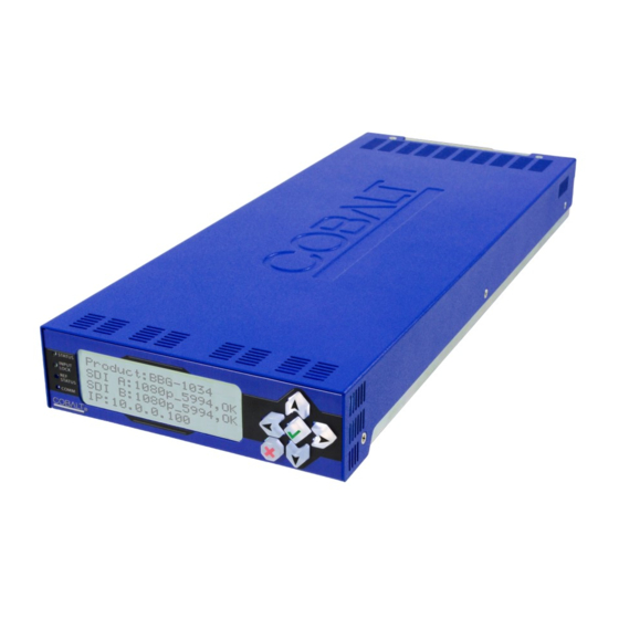
Chapter 2. Installation. BBG-1034-AUD-PRO-DSP Front Panel Display and Menu-Accessed Control Figure 3-1 shows and describes the BBG-1034-AUD-PRO-DSP front panel displays and menu-accessed user interface controls. Initial network setup is performed using these controls. BBG-1034-AUDPRO-OM (V1.6) - Page 34 Repeatedly press the button to step up through sub-menus and then to other menus. Access other menu items using buttons. The display backlight automatically brightens with any navigation arrow activity, and then goes dim after a few moments. Figure 3-1 BBG-1034-AUD-PRO-DSP Front Panel Display and Menu Controls BBG-1034-AUD-PRO-DSP PRODUCT MANUAL BBG-1034-AUDPRO-OM (V1.6)
-
Page 35: Connecting Bbg-1034-Aud-Pro-Dsp To Your Network
Note: Current IP address of BBG-1034-AUD-PRO-DSP can now be checked from the front panel by accessing this at any point. 6. At this point, BBG-1034-AUD-PRO-DSP can now be accessed with a web browser pointing to the configured address. Browse to the configured address and check connectivity. -
Page 36: Finding A Bbg-1034-Aud-Pro-Dsp Device In Dashboard
Connecting BBG-1034-AUD-PRO-DSP To Your Network Finding a BBG-1034-AUD-PRO-DSP Device in DashBoard (See Figure 3-2) If BBG-1034-AUD-PRO-DSP is configured with an address within a network also available via DashBoard, a BBG-1034-AUD-PRO-DSP device appears as a frame entity in the DashBoard Basic Tree View. -
Page 37: Control And Display Descriptions
BBG-1034-AUD-PRO-DSP device are organized into function menus, which consist of parameter groups as shown below. Figure 3-3 shows how the BBG-1034-AUD-PRO-DSP device and its menus are organized, and also provides an overview of how navigation is performed between devices, function menus, and parameters. -
Page 38: Web User Interface
In this example, the Framesync main menu tab is selected, with the overall pane now showing all sub-menu items related to the framesync function. Clicking another main menu tab immediately displays the pane related to the selected main menu tab. Figure 3-4 Typical Web UI Display and Controls BBG-1034-AUD-PRO-DSP PRODUCT MANUAL BBG-1034-AUDPRO-OM (V1.6) -
Page 39: Display Theme
Control and Display Descriptions Display Theme (See Figure 3-5.) Clicking Settings The BBG-1034-AUD-PRO-DSP user interface theme selection offers light and dark themes suited for various users and environments. Clicking Settings opens a pane where the display Theme can be set With Settings open, Theme is selected to display a pallet of available themes. -
Page 40: Checking Bbg-1034-Aud-Pro-Dsp Device Information
Checking BBG-1034-AUD-PRO-DSP Device Information Checking BBG-1034-AUD-PRO-DSP Device Information The operating status and software version the BBG-1034-AUD-PRO-DSP device can be checked by clicking the Status main menu tab. Figure 3-6 shows and describes the BBG-1034-AUD-PRO-DSP device information status display. Note: Proper operating status is denoted by green icons for the status indicators shown in Figure 3-6. -
Page 41: Bbg-1034-Aud-Pro-Dsp Function Menu List And Descriptions
BBG-1034-AUD-PRO-DSP Function Menu List and BBG-1034-AUD-PRO-DSP Function Menu List and Descriptions Table 3-1 individually lists and describes each BBG-1034-AUD-PRO-DSP function menu and its related list selections, controls, and parameters. Where helpful, examples showing usage of a function are also provided. Table 3-1 is primarily based upon using DashBoard™... -
Page 42: Audio Dsp Setup Controls
BBG-1034-AUD-PRO-DSP Function Menu List and Descriptions Table 3-1 BBG-1034-AUD-PRO-DSP Function Menu List Provides controls for enabling licensed DSP functions, routing inputs and outputs to and from the DSP functions, and setting individual parametric settings for Audio DSP Setup Controls each DSP function. - Page 43 Setup/Operating Instructions BBG-1034-AUD-PRO-DSP Function Menu List and Table 3-1 BBG-1034-AUD-PRO-DSP Function Menu List — continued (continued) Input Mixer path positioning locates the DSP pipeline to receive basic external inputs coming into the device (in this example, Emb Ch 1 and Ch 2 feeding DSP A L and DSP A R), and then allows DSP processed output channels to be directed to the internal Audio Bus channels by selecting Audio DSP channels as sources for destination Audio Bus channels via the Input Audio Routing/Controls.
- Page 44 BBG-1034-AUD-PRO-DSP Function Menu List and Descriptions Table 3-1 BBG-1034-AUD-PRO-DSP Function Menu List — continued (continued) core usage Example Multiple DSP Process Audio Routing and DSP Setup In this example, single DSP pipeline DSP A is setup to: • Receive an embedded PCM pair from the basic device input audio (input mixer positioning).
- Page 45 Setup/Operating Instructions BBG-1034-AUD-PRO-DSP Function Menu List and Table 3-1 BBG-1034-AUD-PRO-DSP Function Menu List — continued (continued) When a DSP pipeline is enabled for any function by checking any checkbox like that shown above, the sub-tabs for the related DSP in the lower pane expose all the setup functions required for the selected processes. In this example, we’ll start with the Source Selection function since this is the first step in setting up a DSP.
- Page 46 BBG-1034-AUD-PRO-DSP Function Menu List and Descriptions Table 3-1 BBG-1034-AUD-PRO-DSP Function Menu List — continued (continued) With source selection having been set, now we proceed to setting up the Upmixer. In our example we are sourcing from a stereo PCM pair, so Crossfade does not need to be considered (Mode can be set to Auto or Always Upmix). For cases where 5.1-channel PCM is used as an input, and may already carry 5.1 content, the Threshold and Auto Crossfade...
- Page 47 Setup/Operating Instructions BBG-1034-AUD-PRO-DSP Function Menu List and Table 3-1 BBG-1034-AUD-PRO-DSP Function Menu List — continued (continued) Our final processing step in this example is setting DSP A to also provide a Dolby 5.1 encoded pair. When a Dolby encoder is checked (enabled), the Dolby Digital Encoder and Dolby Digital Encoder Metadata sub-tabs appear, which allow setup of the Dolby encoded pair.
- Page 48 BBG-1034-AUD-PRO-DSP Function Menu List and Descriptions Table 3-1 BBG-1034-AUD-PRO-DSP Function Menu List — continued (continued) Routing the DSP Audio Outputs On the Device Again, depending on whether the DSP is positioned at the device input or output mixer, Audio DSP processed outputs are available as follows: •...
- Page 49 Setup/Operating Instructions BBG-1034-AUD-PRO-DSP Function Menu List and Table 3-1 BBG-1034-AUD-PRO-DSP Function Menu List — continued (continued) As mentioned earlier, a separate DSP pipeline (DSP E) has been set up in this example to provide a SAP Dolby 2.0 pair, with this DSP being positioned at the output mixer in this example. Shown below is the routing that provides this.
- Page 50 BBG-1034-AUD-PRO-DSP Function Menu List and Descriptions Table 3-1 BBG-1034-AUD-PRO-DSP Function Menu List — continued (continued) Note: This subsection of the Audio DSP presentation covers the specific controls and settings of the DSP enable setup pane, signal routing to and from DSP blocks, and the specific DSP blocks themselves. Reading and understanding the overview on the preceding pages is strongly recommended before proceeding to the descriptions below.
- Page 51 Setup/Operating Instructions BBG-1034-AUD-PRO-DSP Function Menu List and Table 3-1 BBG-1034-AUD-PRO-DSP Function Menu List — continued (continued) • Audio DSP Pipeline Select/Setup Pane The lower pane that displays when the Audio DSP tab is opened allows “going into” each enabled DSP pipeline, and setting up attributes for the...
- Page 52 BBG-1034-AUD-PRO-DSP Function Menu List and Descriptions Table 3-1 BBG-1034-AUD-PRO-DSP Function Menu List — continued (continued) Note: As noted earlier, appearance of lower sub-tabs shown here depend on DSP function(s) selected. Sub-tabs only appear where required in setting up a selected DSP function(s).
- Page 53 Setup/Operating Instructions BBG-1034-AUD-PRO-DSP Function Menu List and Table 3-1 BBG-1034-AUD-PRO-DSP Function Menu List — continued (continued) • Real-Time Loudness Leveler Setup (Option +DSP-RTLL only) Provides controls for setting up Real Time Loudness Leveler loudness processing. Sub-Tab • Enable sets RTLL to enabled or bypassed.
- Page 54 BBG-1034-AUD-PRO-DSP Function Menu List and Descriptions Table 3-1 BBG-1034-AUD-PRO-DSP Function Menu List — continued (continued) Tips for Using RTLL (cont.) Loudness Leveler Control Settings Recommendations • Loudness Target: -24 LKFS (ATSC), -23 LKFS (EBU) • Enabled (RTLL master enable control): Enabled •...
- Page 55 Setup/Operating Instructions BBG-1034-AUD-PRO-DSP Function Menu List and Table 3-1 BBG-1034-AUD-PRO-DSP Function Menu List — continued (continued) • Dolby Decoder Setup Sub-Tab (Option +DSP-DEC only) Provides controls for setting up Dolby Decoder. Note: See Source Selection Sub-Tab (p. 3-20) for routing desired Dolby pair to decoder input.
-
Page 56: Input Video Controls
BBG-1034-AUD-PRO-DSP Function Menu List and Descriptions Table 3-1 BBG-1034-AUD-PRO-DSP Function Menu List — continued Allows manual or failover selection of SDI program video inputs and displays status and raster format of received SDI video. Input Video Controls • Input Video Source Selects the input video source to be applied to the device’s program... -
Page 57: Output Video Mode Controls
Setup/Operating Instructions BBG-1034-AUD-PRO-DSP Function Menu List and Table 3-1 BBG-1034-AUD-PRO-DSP Function Menu List — continued Allows selection of each of the four video output coaxial connectors as processed SDI out or reclocked SDI out. Also provides CVBS parameter controls and test pattern output controls for CVBS output. -
Page 58: Framesync
BBG-1034-AUD-PRO-DSP Function Menu List and Descriptions Table 3-1 BBG-1034-AUD-PRO-DSP Function Menu List — continued (Option +FS only) Provides video frame sync/delay offset control and output control/loss of program video failover selection controls. Framesync • Framesync Enable/Disable Control Provides master enable/disable of all framesync functions/controls. - Page 59 Setup/Operating Instructions BBG-1034-AUD-PRO-DSP Function Menu List and Table 3-1 BBG-1034-AUD-PRO-DSP Function Menu List — continued (continued) • Program Video Output Mode Select Provides a convenient location to select between program video output and other technical outputs from the choices shown to the left and described below.
- Page 60 BBG-1034-AUD-PRO-DSP Function Menu List and Descriptions Table 3-1 BBG-1034-AUD-PRO-DSP Function Menu List — continued (continued) With framesync enabled, provides the following controls for offsetting the • Output Video Reference Offset Controls output video from the reference: • Vertical (Lines) – sets vertical delay (in number of lines of output video) between the output video and the frame sync reference.
-
Page 61: Scaler
Setup/Operating Instructions BBG-1034-AUD-PRO-DSP Function Menu List and Table 3-1 BBG-1034-AUD-PRO-DSP Function Menu List — continued (Option +UDX only.) Provides up/down/ cross-converter, aspect ratio controls, and user H/V controls. Scaler • Scaler Enable Control Enables or disables Scaler function. Note: When scaler is disabled, all ancillary data is passed from input to output intact. - Page 62 BBG-1034-AUD-PRO-DSP Function Menu List and Descriptions Table 3-1 BBG-1034-AUD-PRO-DSP Function Menu List — continued (continued) • 3:2 Alignment Optimization Selector Provides selection to optimize 3:2 pulldown conversion where timecode or other selections shown are to be relied upon to indicate frame transitions.
- Page 63 Setup/Operating Instructions BBG-1034-AUD-PRO-DSP Function Menu List and Table 3-1 BBG-1034-AUD-PRO-DSP Function Menu List — continued (continued) • User-defined Aspect Ratio Controls Aspect Ratio Horizontal and Aspect Ratio Vertical controls adjust horizontal and vertical zoom percentage. Settings less than (<) 100% provide zoom-out;...
-
Page 64: Video Delay Controls
BBG-1034-AUD-PRO-DSP Function Menu List and Descriptions Table 3-1 BBG-1034-AUD-PRO-DSP Function Menu List — continued Provides video delay controls. These controls are used to restore lip sync when using audio DSP functions such as RTLL and Dolby encoding. Video Delay Controls Note: On device licensed with Add Framesync (option +FS), this tab does not appear. -
Page 65: Input Audio Status
Setup/Operating Instructions BBG-1034-AUD-PRO-DSP Function Menu List and Table 3-1 BBG-1034-AUD-PRO-DSP Function Menu List — continued Displays signal status and payload for embedded and discrete audio received by the device. Input Audio Status Individual signal status and peak level displays for embedded audio input pairs, and AES/analog input pairs as described below. -
Page 66: Input Audio Routing/Controls
BBG-1034-AUD-PRO-DSP Function Menu List and Descriptions Table 3-1 BBG-1034-AUD-PRO-DSP Function Menu List — continued Provides audio routing, gain, per-channel/bulk audio delay controls, and audio meters. These controls route selected audio sources onto the device 16-channel internal bus (which is used for all audio processing). - Page 67 Setup/Operating Instructions BBG-1034-AUD-PRO-DSP Function Menu List and Table 3-1 BBG-1034-AUD-PRO-DSP Function Menu List — continued (continued) Note: • Default factory preset routing routes embedded Ch 1 thru Ch 16 to bus channels Audio Bus Ch 1 thru Ch 16. •...
- Page 68 BBG-1034-AUD-PRO-DSP Function Menu List and Descriptions Table 3-1 BBG-1034-AUD-PRO-DSP Function Menu List — continued (continued) • Per-Channel Audio/Video Delay Offset Controls Offset control adds or reduces (offsets) channel audio delay from the matching video delay (audio delay offset setting adds or removes delay in addition to any delay included by other actions).
- Page 69 Setup/Operating Instructions BBG-1034-AUD-PRO-DSP Function Menu List and Table 3-1 BBG-1034-AUD-PRO-DSP Function Menu List — continued Input Flex Mix – Provides a 16-channel mixer in which each of the inputs can be mixed onto up to 16 independent output summing nodes. Each input channel has independent gain and mute controls.
- Page 70 BBG-1034-AUD-PRO-DSP Function Menu List and Descriptions Table 3-1 BBG-1034-AUD-PRO-DSP Function Menu List — continued (continued) Note: • Flex Mix input channels Flex Mix 2 thru Flex Mix 16 have controls identical to that described here for Flex Mix 1. Therefore, only the Flex Mix 1 controls are shown here.
-
Page 71: Output Audio Routing/Controls
Gain controls allow relative gain (in dB) control for the corresponding destination Embedded Audio Group channel. (-80 to +20 dB range in 1.0 dB steps; unity = 0 dB) Note: Although the BBG-1034-AUD-PRO-DSP can pass non-PCM data ® such as Dolby E or AC-3, setting the gain control to any setting other than default 0 will corrupt Dolby data. - Page 72 Gain controls allow relative gain (in dB) control for the corresponding destination AES output channel. (-80 to +20 dB range in 1.0 dB steps; unity = 0 dB) Note: Although the BBG-1034-AUD-PRO-DSP can pass non-PCM data ® such as Dolby E or AC-3, setting the gain control to any setting other than default 0 will corrupt Dolby data.
- Page 73 Setup/Operating Instructions BBG-1034-AUD-PRO-DSP Function Menu List and Table 3-1 BBG-1034-AUD-PRO-DSP Function Menu List — continued Provides an audio crosspoint allowing the audio source selection for each analog audio output channel. Also provides Gain, Phase Invert, and Muting controls and peak level meters for each output channel.
- Page 74 BBG-1034-AUD-PRO-DSP Function Menu List and Descriptions Table 3-1 BBG-1034-AUD-PRO-DSP Function Menu List — continued Provides audio down-mix audio routing selections that multiplexes any five audio channel sources into a stereo pair. • Downmixer Source Controls Left Channel Input thru Right Surround Channel Input select the five audio bus source channels to be used for the downmix.
- Page 75 Setup/Operating Instructions BBG-1034-AUD-PRO-DSP Function Menu List and Table 3-1 BBG-1034-AUD-PRO-DSP Function Menu List — continued Output Flex Mix – Provides a 16-channel mixer in which each of the inputs can be mixed onto up to 16 independent output summing nodes. The input sources are the device processed audio bus channels.
-
Page 76: Timecode
BBG-1034-AUD-PRO-DSP Function Menu List and Descriptions Table 3-1 BBG-1034-AUD-PRO-DSP Function Menu List — continued Provides timecode data extraction from various sources, and provides formatting and re-insertion controls for inserting the timecode into the output video. Timecode Shown below is an example in which received 525i 5994 SDI video with VITC waveform timecode is being processed to output ATC_VITC timecode. - Page 77 Setup/Operating Instructions BBG-1034-AUD-PRO-DSP Function Menu List and Table 3-1 BBG-1034-AUD-PRO-DSP Function Menu List — continued (continued) Audio LTC controls described below only appear on devices with +LTC licensed optional feature. This feature allows audio LTC from an audio channel to be used as a timecode source, with conversion to a selected SMPTE 12M format on the output video.
- Page 78 BBG-1034-AUD-PRO-DSP Function Menu List and Descriptions Table 3-1 BBG-1034-AUD-PRO-DSP Function Menu List — continued (continued) • Source Priority Selects the priority assigned to each of the four supported external formats, and internal Free Run in the event the preferred source is unavailable.
- Page 79 Setup/Operating Instructions BBG-1034-AUD-PRO-DSP Function Menu List and Table 3-1 BBG-1034-AUD-PRO-DSP Function Menu List — continued (continued) • Output Status Display Displays the current content and source being used for the timecode data as follows: • Output status OK (in this example, SDI VITC timecode received and outputted).
- Page 80 BBG-1034-AUD-PRO-DSP Function Menu List and Descriptions Table 3-1 BBG-1034-AUD-PRO-DSP Function Menu List — continued (continued) • HD ATC_LTC Insertion Control For HD output, enables or disables ATC_LTC timecode insertion into the output video, and selects the line number for ATC_LTC timecode data.
-
Page 81: Reticules
Reticules Typical Reticule/Overlay Marker Insertions The BBG-1034-AUD-PRO-DSP allows any combination of the reticule/overlay markers to be applied to the output video. Sizing and other characteristics for each type of marker can be set as described below. Safe Action Area (SAA) Reticule... - Page 82 BBG-1034-AUD-PRO-DSP Function Menu List and Descriptions Table 3-1 BBG-1034-AUD-PRO-DSP Function Menu List — continued (continued) • Safe Title Area (STA) Controls • STA provides enable/disable of safe title area graticule insertion. • STA Height and STA Width control height and width of insertion (from 0% to 100% of 4:3 outputted image area).
- Page 83 Setup/Operating Instructions BBG-1034-AUD-PRO-DSP Function Menu List and Table 3-1 BBG-1034-AUD-PRO-DSP Function Menu List — continued (continued) • Center Cross Controls • Center Cross provides enable/disable of center cross insertion. • Cross Height and Width control height of vertical line and width of horizontal line (from 0% to 100% of 4:3 outputted image area).
-
Page 84: Video Quality Events
BBG-1034-AUD-PRO-DSP Function Menu List and Descriptions Table 3-1 BBG-1034-AUD-PRO-DSP Function Menu List — continued (Option +QC only) Sets quality check screening and thresholds for video quality event alerts. When a quality events occur, the event(s) can be used by the Events Setup function to invoke input routing or other changes. -
Page 85: Audio Detect Events Setup Controls
Setup/Operating Instructions BBG-1034-AUD-PRO-DSP Function Menu List and Table 3-1 BBG-1034-AUD-PRO-DSP Function Menu List — continued (Option +QC only) Sets audio level screening and thresholds for audio silence/presence event alerts on embedded and/or AES discrete audio in. When an audio events occur, the event(s) can be used by the... -
Page 86: Closed Captioning
BBG-1034-AUD-PRO-DSP Function Menu List and Descriptions Table 3-1 BBG-1034-AUD-PRO-DSP Function Menu List — continued Provides support for closed captioning setup. Also provides controls for setting closed captioning absence and presence detection thresholds. Closed Captioning Note: Closed Captioning tab appears only on devices licensed with +UDX (scaler option). The closed captioning controls are used to extract and regenerate closed captioning removed by the scaler. -
Page 87: Ancillary Data Proc Controls
Setup/Operating Instructions BBG-1034-AUD-PRO-DSP Function Menu List and Table 3-1 BBG-1034-AUD-PRO-DSP Function Menu List — continued Provides controls for VANC/HANC ancillary data de-embedding and embedding to and from program video stream. Data can be extracted and inserted within the device (Bridge mode), or inserted and/or extracted to and from external interfaces via serial or IP interfaces. - Page 88 BBG-1034-AUD-PRO-DSP Function Menu List and Descriptions Table 3-1 BBG-1034-AUD-PRO-DSP Function Menu List — continued IP Port Setup sub-tab provides IP setup for UDP IP communications. • Card IP Receive Setup/Status Shows device receiving IP address/status and sets port as follows: •...
- Page 89 Setup/Operating Instructions BBG-1034-AUD-PRO-DSP Function Menu List and Table 3-1 BBG-1034-AUD-PRO-DSP Function Menu List — continued Data-Over-Audio sub-tab provides controls that allow SMPTE 337/338/339 non-PCM data to be embedded and de-embedded on embedded audio pairs, offering a very convenient self-contained transport within the program stream physical media.
-
Page 90: Comm Ports Setup Controls
BBG-1034-AUD-PRO-DSP Function Menu List and Descriptions Table 3-1 BBG-1034-AUD-PRO-DSP Function Menu List — continued Provides controls for setting up the two COMM (serial) ports for LTC or ANC functions, and setting comm protocol for each port. COMM Ports Setup Controls •... - Page 91 Setup/Operating Instructions BBG-1034-AUD-PRO-DSP Function Menu List and Table 3-1 BBG-1034-AUD-PRO-DSP Function Menu List — continued (continued) • Insertion Sync Byte Control Allows use of a sync byte from receiver back to sending source to synchronize communication between receive and sending source as follows: •...
-
Page 92: Presets
BBG-1034-AUD-PRO-DSP Function Menu List and Descriptions Table 3-1 BBG-1034-AUD-PRO-DSP Function Menu List — continued Allows user control settings to be saved in a Preset and then loaded (recalled) as desired, and provides a one-button restore of factory default settings. Presets •... - Page 93 Setup/Operating Instructions BBG-1034-AUD-PRO-DSP Function Menu List and Table 3-1 BBG-1034-AUD-PRO-DSP Function Menu List — continued (continued) • Preset Save/Load Controls • Select Preset: drop-down allows a preset saved above to be selected to be loaded or deleted (in this example, custom preset “IRD Rcv122”).
-
Page 94: Gpo Setup Controls
BBG-1034-AUD-PRO-DSP Function Menu List and Descriptions Table 3-1 BBG-1034-AUD-PRO-DSP Function Menu List — continued (continued) Download (save) card presets to a Upload (open) card presets from a network network computer by clicking computer by clicking Upload Download Presets – Save at the at the bottom of bottom of the Presets page. -
Page 95: Event Setup Controls
Setup/Operating Instructions BBG-1034-AUD-PRO-DSP Function Menu List and Table 3-1 BBG-1034-AUD-PRO-DSP Function Menu List — continued Provides event-based loading allowing a defined action to be automatically engaged upon various received signal status. Actions can be “canned” control commands or user-defined by going to a user preset. - Page 96 BBG-1034-AUD-PRO-DSP Function Menu List and Descriptions Table 3-1 BBG-1034-AUD-PRO-DSP Function Menu List — continued (continued) In the example here for Event 1, the Video Quality Events tab is set to screen for frozen video on Input A. When detected, this status can be used here (Video Quality set to “Input A Event Engaged”...
- Page 97 Setup/Operating Instructions BBG-1034-AUD-PRO-DSP Function Menu List and Table 3-1 BBG-1034-AUD-PRO-DSP Function Menu List — continued (continued) User States is a special column which allows a logic state to be set (similar to a register or latch) whenever a defined condition is first triggered.
- Page 98 BBG-1034-AUD-PRO-DSP Function Menu List and Descriptions Table 3-1 BBG-1034-AUD-PRO-DSP Function Menu List — continued Provides three general-purpose timers that can be triggered to start, pause, reset, or stop upon event actions. The state of each timer, in turn, can also be used to invoke other actions.
-
Page 99: Admin
(Thermal shutdown is enabled by default). CAUTION Admin The BBG-1034-AUD-PRO-DSP FPGA is designed for a normal-range operating temperature around 85° C core temperature. Operation in severe conditions exceeding this limit for non-sustained usage are within device operating safe parameters, and can be allowed by setting this control to Disable. - Page 100 BBG-1034-AUD-PRO-DSP Function Menu List and Descriptions Table 3-1 BBG-1034-AUD-PRO-DSP Function Menu List — continued (continued) Firmware upgrade controls allow a selected firmware version (where • Firmware Upgrade Controls multiple versions can be uploaded to the device’s internal memory) to invoke an upgrade to a selected version either instantly, or set to install on the next device reboot (thereby allowing upgrade downtime to be controlled at a scheduled point in time).
-
Page 101: User Log
Setup/Operating Instructions BBG-1034-AUD-PRO-DSP Function Menu List and Table 3-1 BBG-1034-AUD-PRO-DSP Function Menu List — continued (continued) • Card Check and Restore Utilities Memory Test allows all cells of the device FPGA memory to be tested. This control should only be activated under direction of product support. -
Page 102: Alarms Setup Controls
BBG-1034-AUD-PRO-DSP Function Menu List and Descriptions Table 3-1 BBG-1034-AUD-PRO-DSP Function Menu List — continued Provides controls for setting up controls which screen for and propagate input program video alarms for video, audio, and ancillary data defect conditions. Conditions and alarm status can be propagated as Alarms Setup Controls DashBoard tree-view frame alarms, downloadable .txt... - Page 103 Setup/Operating Instructions BBG-1034-AUD-PRO-DSP Function Menu List and Table 3-1 BBG-1034-AUD-PRO-DSP Function Menu List — continued (continued) Ancillary Data Alarm Setup sub-tab allows setting up screening engagement and disengagement holdoff for absence of closed captioning packets. Note: • Video screened is the SDI that is selected for the program video/audio path.
- Page 104 BBG-1034-AUD-PRO-DSP Function Menu List and Descriptions Table 3-1 BBG-1034-AUD-PRO-DSP Function Menu List — continued (continued) Audio sub-tabs independently show for all 16 embedded channels any missing audio (whether absent due to low level, mute or unlocked status). Note: Audio screened is the audio associated with the selected SDI program inputs.
- Page 105 Setup/Operating Instructions BBG-1034-AUD-PRO-DSP Function Menu List and Table 3-1 BBG-1034-AUD-PRO-DSP Function Menu List — continued (continued) Alarm Event History shows the eight most-recent alarm events that have been detected (with most-recent at top of list). The alarm severity (as set using the Severity drop-down for each alarm type) sets the “LED” color shown here.
-
Page 106: Uploading Firmware Using Web Interface And Gui
Uploading Firmware Using Web Interface and GUI Firmware (such as upgrades, option keys, and presets .bin files) can be uploaded to BBG-1034-AUD-PRO-DSP directly via the web html5 interface without going through DashBoard (see Figure 3-7). In addition to allowing uploads without needing a DashBoard connection, this method transfers files typically much faster than using DashBoard. -
Page 107: Front Panel User Menus
The front panel menus offers a true standalone means to configure the BBG-1034-AUD-PRO-DSP with no connection to a network required, and is useful where changes need to be done immediately (or in emergency situations) without the benefit of network access. However, the web GUI provides greatly simplified user interfaces as compared to using this menu and the arrow controls. - Page 108 Network Settings (pg 3-3) Closed Captioning (pg 3-54) Output Audio Routing (pg 3-39) IP Addr Input Status Netmask HD Output Line Output Meters 1-8 Gateway CC Emb/Dis Output Meters 9-16 Mode (DHCP/Stat) Audio Bulk Delay 3-76 BBG-1034-AUD-PRO-DSP PRODUCT MANUAL BBG-1034-AUDPRO-OM (V1.6)
-
Page 109: Troubleshooting
Error and Failure Indicator Overview The BBG-1034-AUD-PRO-DSP itself and its remote control provide error and failure indications. Depending on how the BBG-1034-AUD-PRO-DSP is being used (i.e, standalone or network controlled through DashBoard™ or a Remote Control Panel), check all available indications in the event of an error or failure condition. - Page 110 Troubleshooting BBG-1034-AUD-PRO-DSP Front Panel Status/Error Indicators and Display Figure 3-8 shows and describes the BBG-1034-AUD-PRO-DSP front panel indicators and display. These indicators and the display show status and error conditions relating to the device itself and remote (network) communications (where applicable). Because these indicators are part of the device itself and...
-
Page 111: Basic Troubleshooting Checks
Basic Troubleshooting Checks Item Checks Verify power presence and • On the BBG-1034-AUD-PRO-DSP, in all cases when power is being characteristics properly supplied all indicators should be illuminated. Any device showing no illuminated indicators should be cause for concern. • Check the Power Consumed indication for the BBG-1034-AUD-PRO-DSP. - Page 112 Corrective Action BBG-1034-AUD-PRO-DSP No video input present Make certain intended video source is connected to shows Unlocked message in appropriate BBG-1034-AUD-PRO-DSP video input. BBG-1034-AUD-PRO-DSP Info Make certain BNC cable connections are OK. pane Ancillary data (closed captioning, • Control(s) not enabled •...
-
Page 113: In Case Of Problems
December 2015, your SD may not contain the recov- ery files. Contact Product Support to obtain the updated SD card containing both TTS library and SD recovery files. • If unit is a BBG-1000 Series device, remove the top cover before proceeding. 3-81 BBG-1034-AUDPRO-OM (V1.6) BBG-1034-AUD-PRO-DSP PRODUCT MANUAL... - Page 114 • When reprogram is complete, LED turns off, on, and then off • again (entire process takes about 1-1/2 minute). Remove power from the card (remove card from slot or power-down BBG-1000 Series unit). 3-82 BBG-1034-AUD-PRO-DSP PRODUCT MANUAL BBG-1034-AUDPRO-OM (V1.6)
- Page 115 The Cobalt Digital Inc. Technical Support Department will continue to provide advice on any product manufactured by Cobalt Digital Inc., beyond the warranty period without charge, for the life of the product. See Contact Cobalt Digital Inc. (p. 1-21) in Chapter 1, “Introduction“ for contact information. 3-83 BBG-1034-AUDPRO-OM (V1.6)
- Page 116 This page intentionally blank 3-84 BBG-1034-AUD-PRO-DSP PRODUCT MANUAL BBG-1034-AUDPRO-OM (V1.6)
- Page 118 Cobalt Digital Inc. 2506 Galen Drive Champaign, IL 61821 Voice 217.344.1243 • Fax 217.344.1245 www.cobaltdigital.com BBG-1034-AUDPRO-OM (V1.6) Printed in USA...
Need help?
Do you have a question about the BBG-1034-AUD-PRO-DSP and is the answer not in the manual?
Questions and answers