
Related Manuals for mogk PTP 1450


Summary of Contents for mogk PTP 1450
- Page 1 THERMAL PRESS SEMIAUTOMATIC PTP 1450 Version: English - Translation – Instruction Manual and Operation PTP 1450 Code 9391 Review 00...
-
Page 2: Table Of Contents
1.1 Safety Warnings found in this Manual ................4 1.2 Safety Warnings (Equipment) ..................4 2 INTRODUCTION ........................5 2.1 MOGK's QUALITY POLICE ....................5 2.2 MOGK's Costumers ......................5 2.3 About the Equipment ......................6 2.4 About the manual ......................6 3 GENERAL GUIDELINES ...................... - Page 3 14 WARRANTY CERTIFICATE ....................26 15 ANNEX ........................... 27 15.1 Annex I - Initial Procedure .................... 27 15.2 Annex II – Cleaning procedures .................. 28 15.3 Annex III – Procedures for Teflon Replacement ............29 15.4 Annex IV – Digital Controller ..................30 15.4.1 Tradution - Digital Controller ................
-
Page 4: Safety Instructions
1 SAFETY INSTRUCTIONS This guide provides safety instructions in order to present you the correct way. 1.1 Safety Warnings found in this Manual This manual will show you a few signs such us: REGULATION Follow the usage instructions. DANGER! Indicates information that, if ignored, could result in personal injury or even death. -
Page 5: Introduction
THERMAL PRESS SEMIAUTOMATIC PTP-1450 for fabric, another product with the quality and technology that MOGK produces, made with modern concepts of design and project. In order to make the most of your equipment we suggest that you read this manual before using your new machine. -
Page 6: About The Equipment
2.3 About the Equipment The PTP 1450 is a versatile machine with pneumatic drive suitable for: • Sublimations; • screen printing transfers; • termo adhesives embroidery; • finishing prints; 2.4 About the manual This manual contains instructions on how to install, operate and identify problems. For further information and explanation of doubts and specific solutions, please, contact us: Mogk Industry and Trade Machines Limited. -
Page 7: Installing
Picture 1 – Mogk’s nameplate 4 INSTALLING Necessary recommendations for installation of THERMAL PRESS SEMIAUTOMATIC PTP 1450: Install the pneumatic press on perfect leveling conditions without the presence of aggressive agents. Keep the machine at a height that meets the anthropometric characteristics of the operators. -
Page 8: Compressed Air Network Conditions
It must be replaced annually. Filter code: 27563 6 SAFETY (MACHINE) WARNING! The PTP 1450 model has a security system with fixed barrier within the pneumatic cylinder action limit preventing access to risk area. Pic. 2... -
Page 9: Operation
DANGER! The machine cannot be operated without the protections in its surroundings. It is expressly prohibited the removal of protections, except for maintenance by an authorized and qualified professional. Prior to the withdrawal of protective items, the professional who will perform the maintenance must know the equipment safety procedures. -
Page 10: Operating Warning
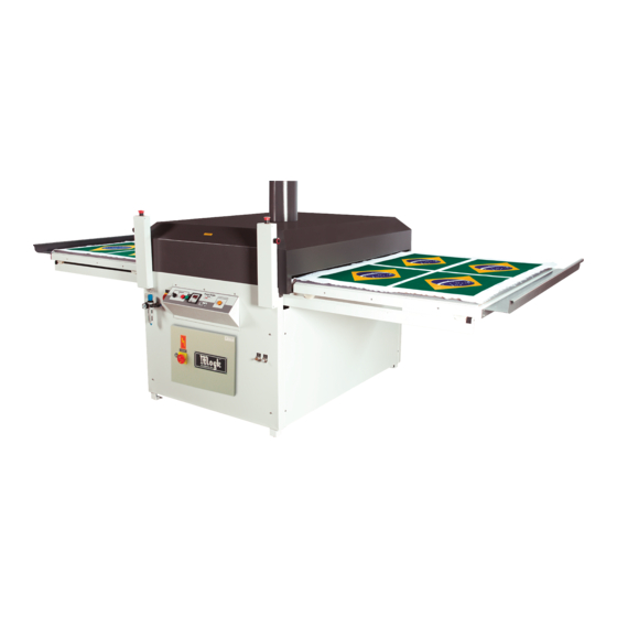
Picture 2 – PTP 1450 Isometric view Table ‘ Control panel Electric panel Manometer 7.1 Operating warning ATENTION! Before operating the calender, operators must be enabled, qualified, trained or authorised. 7.2 Operating Procedures Plug the power cord to the machine as indicated on page 16;... -
Page 11: Speed And Pressure Control
to set the process parameters (temperature and time) perform the adjust it using the digital control panel. Pic.3-D. Place the protective paper on the felt (Kraft or similar role) and the material to be worked with on the table (Pic. 2) and position the transfer with the picture or design facing the material, move the table in the longitudinal direction to the pressing zone, the pressing process will start, wait for the time selected in the digital control;... -
Page 12: Digital Controller - Setting Parameters
ADVICE! For transfering using sublimation ink in synthetic material, the lowering of the table should be slow. For transfering using sublimation ink in cotton, the lowering of the table should be fast. 7.4 Digital Controller – Setting Parameters The pneumatic heat press features programmable digital controller, this device provides control of temperature and time. -
Page 13: Security Adhesive Signs
E – Time LED.:Indicates that the timer is on F – Temperature control LED: indicates that the output control is enabled 8 SECURITY ADHESIVE SIGNS The PTP 1450 has safety signs to warn staff and third parties about the risks they are exposed to. -
Page 14: Maintenance
9 MAINTENANCE ATENTION! Maintenance should be performed by a qualified person. DANGER! Always turn off the power supply before any maintenance. EARTH We suggest you to have your machine earthed. HOT SURFACE Prior to any maintenance activities, make sure the machine is cold. 9.1 Cleaning ATENTION Switch off the machine before cleaning. -
Page 15: Technical Assistance
9.3 Technical Assistance DANGER! Only people with technical qualifications are authorized to install, operate and maintenance services of this equipment. All safety instructions in this manual must be followed. The non-observance of this warning may result in life- threatening and / or serious damage to property. WARNING! For safety reasons, we do not recommend any modifications to the equipment. -
Page 16: Technical Data And Information
10 TECHNICAL DATA AND INFORMATION CONDUCTOR ELECTRIC VOLTAGE CIRCUIT BREAKER PHASE / CURRENT NEUTRAL 220V TRIPHASE 34 A 10 mm² 50 A 380V TRIPHASE 20 A 4 mm² 40 A 220V MONOPHASE 59 A 16 mm² 80 A FREQUENCY 60 Hz POWER 13 kW TEMPERATURE CONTROL RANGE... -
Page 17: Pneumatic Scheme
11 Pneumatic Scheme... -
Page 18: Electric Scheme
12.1 Electric diagram – biphasic 220V 12 Electric Scheme... -
Page 19: Electric Diagram - Three-Phase 220V
12.2 Electric diagram – three-phase 220V... -
Page 20: Electric Diagram - Three-Phase 380V
12.3 Electric diagram – three-phase 380V... -
Page 21: Assembly Drawings And Spare Parts
13 ASSEMBLY DRAWINGS AND SPARE PARTS 13.1 Parts list... -
Page 23: General Set
13.2 General Set... -
Page 26: Warranty Certificate
. transport costs and insurance from the place of installation to Mogk, and vice versa are your obligations. If there is need for intervention, expenses such as accommodation and travelling costs should be paid by the costumer. -
Page 27: Annex
15 ANNEX 15.1 Annex I - Initial Procedure Procedure for mounting the rails: • Attention! Be careful not to damage the sensor. • Remove the screws holding the side protection (both sides); Rail • Place the rails on the bracket with the help of the stop screw;... -
Page 28: Annex Ii - Cleaning Procedures
15.2 Annex II – Cleaning procedures Procedures: . Attention! This operation must be done by a treined and qualified professional; . Remove the movel table (A); . Remove the fixing screws and remove the top cover (B); . Remove the two nuts of the top structure (C) . -
Page 29: Annex Iii - Procedures For Teflon Replacement
15.3 Annex III – Procedures for Teflon Replacement Procedures: • To put the teflon coat remove the mounting screws of the upper protection (A); • Open the coat and pass under the hotplate (B); • Select the springs; • Engage the spring in stabilizing rod be careful not to tear the teflon;... -
Page 30: Annex Iv - Digital Controller
15.4 Annex IV – Digital Controller... -
Page 31: Tradution - Digital Controller
15.4.1 Tradution - Digital Controller The Temperature Controller with Proportional is developed to obtain accuracy in temperature and time control simultaneously. The temperature on the thermocouple is continually checked and compared with the set value, when the value is below the set temperature, the heating relay performs accordingly to the preset values (P03, P04) –... - Page 32 TECHNICAL CARACHTERISTICS 110/220 (PRE VOLTAGE ORDERED) 50/60HZ +- APROXIMATED COMSUMPTION TEMOPERATURE RELAY 12Vcc 20mA TIMER RELAY 250 Vca @ 5Aca TEMPERATURE CONTROL RANGE 0-700 oC READING ACCURACY +- 2.00 % F.E. 0 – 999 SEC. ADJUSTMENT RANGE (TIMER) 0 – 60oC ROOM TEMPERTURE 0 –...
Need help?
Do you have a question about the PTP 1450 and is the answer not in the manual?
Questions and answers