
Related Manuals for Pierce HUSKY 12 GPM

Summary of Contents for Pierce HUSKY 12 GPM
- Page 1 HUSKY 12 GPM FOAM SYSTEM © 2017 Pierce Manufacturing Inc. Part No. PM-F-OM131-0517...
-
Page 3: Table Of Contents
2-2.3a ..................2-10 ANIFOLD AND ASTER RAINS 2-2.3b ................... 2-10 LINE ATER HECK ALVE 2-2.3c ......................2-11 ATER LOWMETER 2-2.4 & D ......................2-12 ONTROL ISPLAY Husky 12 Foam System / i © 2017 Pierce Manufacturing Inc. All Rights Reserved. - Page 4 4-7.2 (LVDT) T ................4-14 ALIBRATE RANSDUCER 4-7.3 ....................4-15 ALIBRATE LASS 4-7.4 ....................4-16 ALIBRATE LASS 4-7.5 ........................4-17 ESTORE EFAULTS 4-7.6 ..........................4-18 ROGRAMMING ii / Husky 12 Foam System © 2017 Pierce Manufacturing Inc. All Rights Reserved.
- Page 5 USKY ROPORTIONING YSTEM 4-17.1 C ........................4-35 HARACTERISTICS 4-17.2 R ........................4-35 ECOMMENDATIONS 4-17.3 O ......................4-36 HANGE NFORMATION 4-18 S ........................... 4-37 YSTEM IAGRAMS INDEX Husky 12 Foam System / iii © 2017 Pierce Manufacturing Inc. All Rights Reserved.
- Page 6 TABLE OF CONTENTS iv / Husky 12 Foam System © 2017 Pierce Manufacturing Inc. All Rights Reserved.
-
Page 7: Foreword
Purpose of Manual The information in this manual is for the operation and maintenance of Pierce Husky 12 Proportioning System. It is intended to serve as a guide to assist qualified operators and mechanics in the operation and maintenance of their vehicle. - Page 8 FOREWORD vi / Husky 12 Foam System © 2017 Pierce Manufacturing Inc. All Rights Reserved.
-
Page 9: Safety
The “signal words” of DANGER, WARNING, and CAUTION have specific meanings to alert you to the relative level or probability of the hazard. Take the safety warnings seriously. If you do not understand them or have questions about them, contact Pierce Manufacturing Inc. -
Page 10: List Of Abbreviations
Alcohol Resistant Aqueous Film Forming Foam FFFP Film Forming Fluoro-Protein Gallons per Minute Liquid Crystal Display Liters per Minute NFPA National Fire Protection Association Pounds per Square Inch Revolutions per Minute 1-2 / Husky 12 Foam System © 2017 Pierce Manufacturing Inc. All Rights Reserved. -
Page 11: General
The message displays the interval for cleaning the foam strainer & water strainer, and changing the hydraulic oil. These messages will appear after 20 hours of foam system operation if not reset during normal maintenance. Husky 12 Foam System / 2-1 © 2017 Pierce Manufacturing Inc. All Rights Reserved. -
Page 12: 2-1.6 Flush System
The system is delivered with ISO 68 hydraulic oil. 2-2 / Husky 12 Foam System © 2017 Pierce Manufacturing Inc. All Rights Reserved. -
Page 13: 2-2.1A Hydraulic Gear Pump
The Hydraulic Filter is a pressure bypass element-type filter manufactured by Hydac. The filter element is replaceable. The unit is installed inside the pumphouse and is used to filter the pressurized hydraulic loop. The replacement part number for the filter element is Pierce P/N 1460998. Husky 12 Foam System / 2-3... -
Page 14: 2-2.1C Hydraulic Oil Reservoir
Refer to hydraulic oil for the Husky 12 system. 2-2.1d Hydraulic Oil Cooler Figure 2-4: Hydraulic Oil Cooler Hydraulic Oil Cooling Water In/Out In/Out 1004 2-4 / Husky 12 Foam System © 2017 Pierce Manufacturing Inc. All Rights Reserved. -
Page 15: 2-2.1E Hydraulic Manifold Block
The control head will display a warning message when the foam tank being used is below one quarter tank. Husky 12 Foam System / 2-5 © 2017 Pierce Manufacturing Inc. All Rights Reserved. -
Page 16: 2-2.2B Foam Supply Valve
The foam end of the pump is brass construction and contains 4 cartridge type check valves to prevent foam from flowing the wrong direction in the pump. 2-6 / Husky 12 Foam System © 2017 Pierce Manufacturing Inc. All Rights Reserved. -
Page 17: 2-2.2D Foam Selector Valve
A “CHECK SELECTOR VALVE” message is displayed by the control head in the event that the valve is not in the correct position for the operation selected. Husky 12 Foam System / 2-7 © 2017 Pierce Manufacturing Inc. All Rights Reserved. -
Page 18: 2-2.2E Panel Mounted Strainer / External Pick-Up Connection
This connection also functions as the Class A tank fill (when equipped with tank fill option) and as the foam tank drain. 2-8 / Husky 12 Foam System © 2017 Pierce Manufacturing Inc. All Rights Reserved. -
Page 19: 2-2.2F Pick-Up Hose
This system consists of an in-line water check valve, water flowmeter and flowmeter installation tee. The size of the check valve and the flowmeter installation tee are dependent on the number of foam/ water discharges in the system. Husky 12 Foam System / 2-9 © 2017 Pierce Manufacturing Inc. All Rights Reserved. -
Page 20: 2-2.3A Manifold And Master Drains
The In-line Water Check Valve prevents foam from entering the water pump and the remainder of the water system. It is installed in the water piping, before the foam injection manifold and the water flowmeter. 2-10 / Husky 12 Foam System © 2017 Pierce Manufacturing Inc. All Rights Reserved. -
Page 21: 2-2.3C Water Flowmeter
The Water Flowmeter measures the flow of water supplied to the foam/water discharges before foam is injected. This controls the amount of foam that is injected when the Husky 12 foam system is turned on. Husky 12 Foam System / 2-11 © 2017 Pierce Manufacturing Inc. All Rights Reserved. -
Page 22: 2-2.4 Control Head & Display
Detailed instructions on the operation of each mode can Section 3, “Operation”. be found in 2-12 / Husky 12 Foam System © 2017 Pierce Manufacturing Inc. All Rights Reserved. -
Page 23: Foam System Operation
NOTE: The only flush needed is to run the hose until it is mostly free of bubbles. The foam pump is designed to be flooded with foam. Husky 12 Foam System / 3-1 © 2017 Pierce Manufacturing Inc. All Rights Reserved. -
Page 24: 3-1.2 Classa Foam - D
Class B valve opening, provided the water flowmeter senses water flow. 2. Use the ARROW UP / ARROW DOWN buttons to change percentage (if needed). “General Flushing Information” page 3-5. 3. See 3-2 / Husky 12 Foam System © 2017 Pierce Manufacturing Inc. All Rights Reserved. -
Page 25: 3-1.4 Classb Foam - D
3. The default percentage will remain the same as the on-board Class B tank current setting. 4. Use the ARROW UP / ARROW DOWN buttons to change percentage (if needed). “General Flushing Information” page 3-5. 5. See Husky 12 Foam System / 3-3 © 2017 Pierce Manufacturing Inc. All Rights Reserved. -
Page 26: 3-1.5 Choosing A Foam
Whenever there is a foam class change, the system will automatically flush the pump with water to prevent mixing of foam types in the pump. 4. Use the UP/DOWN arrows to highlight the desired foam source and press ENTER. 3-4 / Husky 12 Foam System © 2017 Pierce Manufacturing Inc. All Rights Reserved. -
Page 27: Flushing System
This automatic flush time can be adjusted in the set-up mode, refer to instructions. In addition to the automatic flush, it is recommended to do an additional manual flush to ensure the system is completely free of contaminates. Husky 12 Foam System / 3-5 © 2017 Pierce Manufacturing Inc. All Rights Reserved. -
Page 28: 3-2.2 Manual Flushm
4. If water is flowing, the screen will go to the SYSTEM FLUSH TIME screen and count down the preset seconds for the flush. At the end of the flush, you will be returned to the normal run mode screen. 3-6 / Husky 12 Foam System © 2017 Pierce Manufacturing Inc. All Rights Reserved. -
Page 29: Priming System
Water must be flowing through an open foam discharge OR open foam pump discharge drain to give the foam solution somewhere to go. NOTE: Perform steps (2) thru (4) if the foam system is installed on a Pierce Ultimate Configuration (PUC) apparatus, otherwise skip to step (5). -
Page 30: Filling Foam Tank
This tube goes into the tank and allows the foam concentrate to enter under the surface of foam currently in the tank to reduce aeration of the foam per NFPA. 3-8 / Husky 12 Foam System © 2017 Pierce Manufacturing Inc. All Rights Reserved. -
Page 31: 3-4.2 Pick - Up Hosem
6. The tank will fill until the full level is reached in the tank. 7. Remove pick-up hose from foam pump inlet. Husky 12 Foam System / 3-9 © 2017 Pierce Manufacturing Inc. All Rights Reserved. -
Page 32: Manual Mode
An alternate method would be to set the GPM to a fixed rate and adjust the percentage of foam. 3-10 / Husky 12 Foam System © 2017 Pierce Manufacturing Inc. All Rights Reserved. -
Page 33: Draining The Foam Tank
6. Press ENTER again to turn the Drain System off. 7. Repeat steps 4 through 6 to drain the other tank, or press PAGE to go back. Husky 12 Foam System / 3-11 © 2017 Pierce Manufacturing Inc. All Rights Reserved. - Page 34 OPERATION 3-12 / Husky 12 Foam System © 2017 Pierce Manufacturing Inc. All Rights Reserved.
-
Page 35: Maintenance Introduction
The services of a qualified field engineer to inspect the system, run the tests for start-up, and the annual inspection can be provided. Additional details can be obtained by contacting Pierce Manufacturing. During cold weather, the foam system must be blown out after testing with water. Water cannot remain in the foam system after testing. -
Page 36: Check Current Software
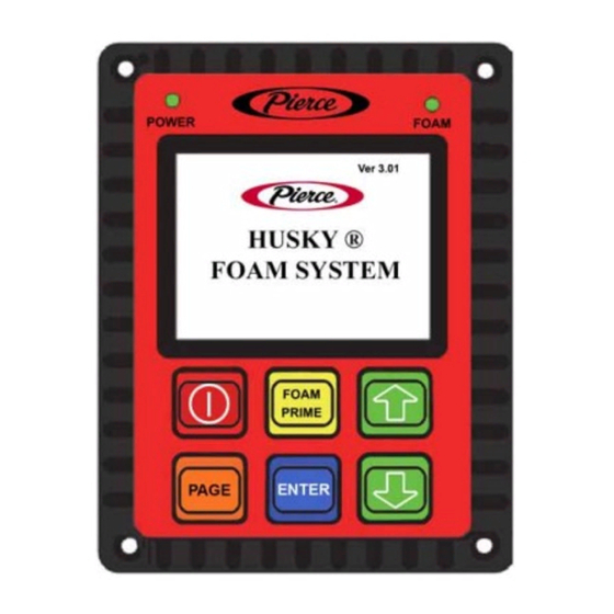
Check Current Software Revision NOTE: This information is also displayed when the system is first turned ON. Figure 4-1: Control Head showing Software Revision SOFTWARE REVISION NUMBER 1567 4-2 / Husky 12 Foam System © 2017 Pierce Manufacturing Inc. All Rights Reserved. -
Page 37: Diagnostics
4. Toggle the UP/DOWN buttons to go to the two screens containing the circuit status of the inputs on the system. 5. Press the PAGE button at any time to go back to the normal run mode screen. Husky 12 Foam System / 4-3 © 2017 Pierce Manufacturing Inc. All Rights Reserved. - Page 38 4. Toggle the UP/DOWN buttons to go to the three screens containing commanded values, actual values, and circuit status of the outputs on the system. 5. Press the PAGE button at any time to go back to the normal run mode screen. 4-4 / Husky 12 Foam System © 2017 Pierce Manufacturing Inc. All Rights Reserved.
-
Page 39: Setup
5. Press and hold the ENTER button. While holding the enter button, press the UP and DOWN arrows simultaneously. The desired selection subcategory screen will appear. Husky 12 Foam System / 4-5 © 2017 Pierce Manufacturing Inc. All Rights Reserved. -
Page 40: Set Up Mode
7. Repeat steps 3 through 6 as necessary to update additional settings. 8. When complete, press the PAGE button 4 times to get back to the home screen. 4-6 / Husky 12 Foam System © 2017 Pierce Manufacturing Inc. All Rights Reserved. - Page 41 1. While in the Parameters screen, press ARROW UP or ARROW DOWN to select Auto Start, then press ENTER. 2. Press ARROW UP or ARROW DOWN to toggle between ON and OFF options. 3. Press ENTER to accept the selection. Husky 12 Foam System / 4-7 © 2017 Pierce Manufacturing Inc. All Rights Reserved.
-
Page 42: 4-6.2 Tank Defaults
5. Using the UP/DOWN buttons, toggle through the list of possible choices. 6. Press the ENTER button to save the setting. 7. Repeat steps 3 through 6 as necessary to update additional settings. 4-8 / Husky 12 Foam System © 2017 Pierce Manufacturing Inc. All Rights Reserved. - Page 43 2. Press ENTER to activate the line. 3. Press ARROW UP or ARROW DOWN to toggle between YES and NO. 4. Press ENTER to accept the selection. Husky 12 Foam System / 4-9 © 2017 Pierce Manufacturing Inc. All Rights Reserved.
- Page 44 3. Using the UP/DOWN buttons, highlight the desired startup source. 4. Press the ENTER button. You will be automatically transfered back to the home screen with that source being selected. 4-10 / Husky 12 Foam System © 2017 Pierce Manufacturing Inc. All Rights Reserved.
-
Page 45: 4-6.4 Set Back Light
6. When the adjustment is complete, press ENTER to save the setting. 7. Repeat steps 3 through 6 to make additional adjustments, or press PAGE to go back. Husky 12 Foam System / 4-11 © 2017 Pierce Manufacturing Inc. All Rights Reserved. - Page 46 6. When the adjustment is complete, press ENTER to save the setting. 7. Repeat steps 3 through 6 to make additional adjustments, or press PAGE to go back. 8. Cycle batteries to confirm changes. 4-12 / Husky 12 Foam System © 2017 Pierce Manufacturing Inc. All Rights Reserved.
-
Page 47: Calibration Mode
300 GPM (high gpm flowmeter setting). Open the discharge valve(s). 7. Press ENTER to begin calibration. Calibration in Process will appear. 8. When calibration is complete, press PAGE to exit CALIBRATION screen. Husky 12 Foam System / 4-13 © 2017 Pierce Manufacturing Inc. All Rights Reserved. - Page 48 The normal voltage reading is 300mv - 700mv (left) and 4300mv - 4800mv (right). 4. When the calibration is complete, press the PAGE button to Exit. 4-14 / Husky 12 Foam System © 2017 Pierce Manufacturing Inc. All Rights Reserved.
- Page 49 = 1.1 GPM.) Using the ARROW UP or ARROW DOWN buttons, enter the GPM flowed. 11. Press ENTER to accept value. 12. Display should read CALIBRATE MODE CLASS A FOAM Husky 12 Foam System / 4-15 © 2017 Pierce Manufacturing Inc. All Rights Reserved.
- Page 50 = 1.1 GPM.) Using the ARROW UP or ARROW DOWN buttons, enter the GPM flowed. 12. Press ENTER to accept value. 13. Display should read CALIBRATE MODE CLASS B FOAM. 4-16 / Husky 12 Foam System © 2017 Pierce Manufacturing Inc. All Rights Reserved.
- Page 51 4. Press PAGE to return to the main screen. 5. Review all settings to ensure the Husky 12 system is set to your desired configuration and settings. Husky 12 Foam System / 4-17 © 2017 Pierce Manufacturing Inc. All Rights Reserved.
- Page 52 The following procedure is used to update software using the interface port located on the back side of the Husky 12 display. • Programming requires an interface cable (Pierce P/N 2513982) and the necessary software, which can be downloaded from www.pierceparts.com. MODE SELECT → SETUP SELECTION → CALIBRATE → RESTORE DEFAULTS 1.
-
Page 53: Maintenance Mode
4. Use the UP/DOWN arrows to select additional timers to clear. 5. Press ENTER to reset the timer(s). 6. When complete, press PAGE to return to the normal operation screen. Husky 12 Foam System / 4-19 © 2017 Pierce Manufacturing Inc. All Rights Reserved. -
Page 54: Troubleshooting
Inspect the check valve at the • Foam should not leak past the injection fitting. injection fitting check valve with system OFF. If fitting leaks, replace. 4-20 / Husky 12 Foam System © 2017 Pierce Manufacturing Inc. All Rights Reserved. - Page 55 “Reset Maintenance foam strainer. appropriate intervals. found in Reminders / Timers” page 4-19. Husky 12 Foam System / 4-21 © 2017 Pierce Manufacturing Inc. All Rights Reserved.
- Page 56 The foam system will not Visual inspection. tank? operate properly without an adequate supply of concentrate. Fill tank with foam. See “Filling Foam Tank” page 3-8. 4-22 / Husky 12 Foam System © 2017 Pierce Manufacturing Inc. All Rights Reserved.
- Page 57 Replace the foam injection check valve. Husky 12 Foam System / 4-23 © 2017 Pierce Manufacturing Inc. All Rights Reserved.
- Page 58 E. Is the wiring OK? The foam system will not Refer to the wiring diagram for circuit operate properly if the information. wiring is faulty. Repair wiring. 4-24 / Husky 12 Foam System © 2017 Pierce Manufacturing Inc. All Rights Reserved.
- Page 59 Check the voltage at the control head. Voltage at the control head should be within .2 volt of the battery voltage. 1146 Repair poor connections, loose pins, etc. Husky 12 Foam System / 4-25 © 2017 Pierce Manufacturing Inc. All Rights Reserved.
- Page 60 No signal from the flowmeter will result in the foam system not operating. Replace flowmeter, see service group 7950-P-001. 4-26 / Husky 12 Foam System © 2017 Pierce Manufacturing Inc. All Rights Reserved.
- Page 61 Open drain on inlet side of foam pump; b. Open foam tank to pump valve; c. Check for foam concentrate. If concentrate is present, foam tank valve is open. Go to Step Q. Husky 12 Foam System / 4-27 © 2017 Pierce Manufacturing Inc. All Rights Reserved.
- Page 62 To isolate the flowmeter page 3-10. in the manual mode? from the system and eliminate it as a possible cause. Replace flowmeter, see service group 7950-P-001. 4-28 / Husky 12 Foam System © 2017 Pierce Manufacturing Inc. All Rights Reserved.
- Page 63 4-37 N. Is the wiring OK? The foam system will not Refer to operate properly if the additional circuit information. wiring is faulty. Repair wiring. Husky 12 Foam System / 4-29 © 2017 Pierce Manufacturing Inc. All Rights Reserved.
- Page 64 Check the voltage at the control head, ckt# 2878, pin 1. Voltage at the control head should be within .2 volt of the battery voltage. 1146 Repair wiring. 4-30 / Husky 12 Foam System © 2017 Pierce Manufacturing Inc. All Rights Reserved.
- Page 65 4-37 have an adequate ground for additional circuit circuit (continuity) for the information. system to operate. 1149 Repair ground circuit. Replace LVDT per service group 7950-P-007. Husky 12 Foam System / 4-31 © 2017 Pierce Manufacturing Inc. All Rights Reserved.
-
Page 66: 4-10. Periodic Operation
Cleanliness Dirt, grease, oil, and debris may cover up a serious problem. Use an approved dry cleaning solvent to clean all metal surfaces. 4-32 / Husky 12 Foam System © 2017 Pierce Manufacturing Inc. All Rights Reserved. -
Page 67: Preventive Maintenance
Item to Check/Service This column tells you the item to be checked or serviced. Procedure This column tells you how to perform the required check or service. Husky 12 Foam System / 4-33 © 2017 Pierce Manufacturing Inc. All Rights Reserved. -
Page 68: 4-13. After Every Use Inspection
Remove clean-out cap and remove basket. Inspect for foreign debris. If any are found, clean the basket with water and reinstall. Water Strainer Water Strainer 1029 4-34 / Husky 12 Foam System © 2017 Pierce Manufacturing Inc. All Rights Reserved. -
Page 69: 4-15. Quarterly Inspection
Husky 12 system. 4-17.2 Recommendations U.S. Oil Multi-Vis 68R, Mobil DTE16M ISO 68 or equivalent. Husky 12 Foam System / 4-35 © 2017 Pierce Manufacturing Inc. All Rights Reserved. -
Page 70: 4-17.3 Oil Changei
Annually, obtain an oil sample and compare to previous results. If the current sample matches previous test results, the oil does not have to be changed. Replace oil and filter if test results indicate oil degradation. 4-36 / Husky 12 Foam System © 2017 Pierce Manufacturing Inc. All Rights Reserved. -
Page 71: 4-18. System Diagrams
MAINTENANCE 4-18. System Diagrams Figure 4-32: Husky 12 Hydraulic Schematic 1563671 Husky 12 Foam System / 4-37 © 2017 Pierce Manufacturing Inc. All Rights Reserved. - Page 72 MAINTENANCE Figure 4-33: Husky 12 Wiring Harness 64-5033-H004 4-38 / Husky 12 Foam System © 2017 Pierce Manufacturing Inc. All Rights Reserved.
- Page 73 MAINTENANCE Figure 4-34: Husky 12 Wiring Harness 64-5033-H004 Husky 12 Foam System / 4-39 © 2017 Pierce Manufacturing Inc. All Rights Reserved.
- Page 74 MAINTENANCE Figure 4-35: Husky 12 Foam System Schematic 1563917 4-40 / Husky 12 Foam System © 2017 Pierce Manufacturing Inc. All Rights Reserved.
- Page 75 Draining Foam Pump After Testing ......2-10 In-line Water Check Valve ..........Introduction Introduction, Preventive Maintenance Checks and ........4-33 Service ......4-33 Explanation of Columns ......External Pick-Up Connection Husky 12 Foam System / Index-1 © 2017 Pierce Manufacturing Inc. All Rights Reserved.
- Page 76 ......... 4-35 Quarterly Inspection ....4-35 Recommendations, Hydraulic Oil Recommended Hydraulic Oil for Husky 12 ....4-35 Proportioning System ..4-19 Reset Maintenance Reminders / Timers Index-2 / Husky 12 Foam System © 2017 Pierce Manufacturing Inc. All Rights Reserved.
Need help?
Do you have a question about the HUSKY 12 GPM and is the answer not in the manual?
Questions and answers