
Related Manuals for Sentinel CCTV CA770


Summary of Contents for Sentinel CCTV CA770
- Page 1 B&W Electric Shutter RearView Camera Installation & Operation CA770 (Camera) FOR MORE INFORMATION WWW.STRATEGICVISTA.COM BEFORE OPERATING THIS SYSTEM, PLEASE READ THIS MANUAL THOROUGHLY AND RETAIN IT FOR FUTURE REFERENCE...
-
Page 2: Safety Precautions
Safety Precautions Before using this unit please read these operating instructions carefully. Take special care to follow th warnings indicated on the unit itself as well as the safety suggestions listed below. Keep them handy for future reference. Power source – The unit should be connected to power supply only of the type described in the operating instructions or as marked on the unit. -
Page 3: Table Of Contents
Table of Contents Safety Precautions………………………………………………………. Introduction……………………………………………………………….. System Contents………………………………………………………… Features…………………………………………………………………... Camera Controls………………………………………………………… Camera Installation……………………………………………………… Connections……………………………………………………………… Operating Instructions………………………………………………….. Care & Maintenance……………………………………………………. Specifications……………………………………………………………. -
Page 4: Introduction
Introduction Thank you for purchasing the Sentinel Black & White Shutter RearView Camera. This camera promotes and prevents backing-up and parking accidents, by allowing to view or check on the traffic behind your vehicle, or when rounding corners (blind spot prevention). The Shutter feature protects the lens by opening only when the camera is in use. -
Page 5: Camera Controls
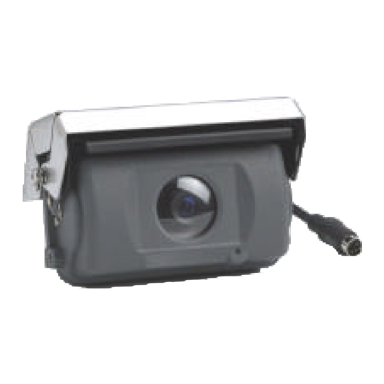
Camera Controls 1. LENS : High Resolution B&W CCD image sensor. 2. SHUTTER : Motor operated shutter prevents soiling of lens when camera is not in use. 3. COVER : Protects camera from direct rain and weathering. 4. CAMERA PLUG : Use this camera plug to connect to the 5m portion of the 2 piece 20m cable (included). -
Page 6: Camera Installation
Camera Installation 1.8M, 4 Pin Cable with mini DIN Plug (male) Camera Cover Camera 20M, 4 Pin 2 piece cable with mini DIN Jack (female) 1. Connect the 1.8 M cable from the camera to the short 5M piece of the 20M (15M + 5 M) 2-piece extension cable provided. - Page 7 Camera Installation Camera Installation 1. At the desired camera mounting position, fit the camera mounting bracket into position using the supplied screws on the center hole and slide hole. 2. Turn the bracket left and right to a correct direction and then tighten the screws.
-
Page 8: Connections
Connections Back of Monitor (MO53/MO73) DC12-24V CAM 1 CAM 2 VIDEO AUDIO Fuse Power cable lead (Red) L=15 m L= 15 m Ground lead (Black) Reverse power lead (Green) L= 5 m L= 1.8 m Camera A L=5 m Waterproof Connector L= 1.8 m Camera B Connect the RED wire to the (12V –24V DC) power terminal, which is... -
Page 9: Operating Instructions
Operating Instructions • When you turn the ignition key to the Accessory or ON position, power is supplied to the monitor and the monitor is in standby (If the Power button is not pushed in) • When you push the power button you can view the picture from the camera manually. -
Page 10: Specifications
Specifications Camera Video Format Pick-up Device 1/3” B&W CCD Pick-up Device 270,000 pixels Fixed Focus Lens 2.5 mm Viewing Angle 130° Diagonal Horizontal Resolution 380 lines Video Output 1V p-p, 75 ohms Minimum Illumination 1 lux Shock Rating Vibration 0 – 2000 Hz Input Voltage Range 9 ~ 12 VDC from the monitor Operating Temperature...
Need help?
Do you have a question about the CA770 and is the answer not in the manual?
Questions and answers