
Related Manuals for Carel VSDU0A0003


Summary of Contents for Carel VSDU0A0003
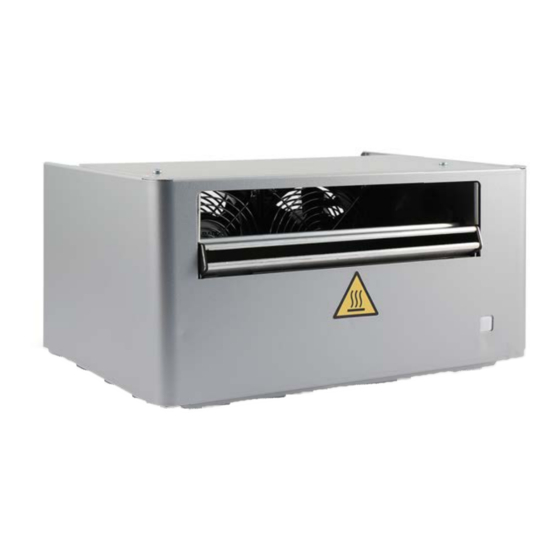
- Page 1 VSDU0A0003 Testata ventilante Steam blower MANUALE D'USO USER MANUAL VSDU0A0003 +030222190 - ITA - ENG Up to date version available on www.carel.com...
- Page 3 CAREL o le sue filiali/ affiliate siano state avvisate della possibilità di danni. PERICOLO SCOSSE ELETTRICHE: l’umidificatore contiene componenti sotto tensione elettrica.
- Page 4 Prima della consegna del in bassa tensione, le prescrizioni per l'installazione dei tubi di prodotto, Carel ha già effettuato le verifiche e i test previsti vapore e dello scarico di condensa, le disposizioni per il dalle direttive Europee e relative norme armonizzate,...
-
Page 5: Table Of Contents
Indice 1. INTRODUZIONE 1.1 Descrizione 2. PREPARAZIONE AL MONTAGGIO 2.1 Prescrizioni 3. MONTAGGIO 3.1 Operazioni preliminari 3.2 Montaggio 4. MANUTENZIONE E PARTI DI RICAMBIO 4.1 Componenti 4.2 Sostituzione componenti 5. CARATTERISTICHE TECNICHE VSDU0A0003 +030222190 rel. 1.4 – 11.02.2021 | 5... -
Page 7: Introduzione
1. Introduzione La testata ventilante per umidificatori isotermici CAREL heaterSteam, humiSteam, gaSteam diffonde il vapore direttamente in ambiente in strutture che non hanno un sistema di distribuzione dell'aria. Descrizione L'apparecchio può essere installato sopra l'umidificatore o fissato a parete (tramite il kit accessorio cod. - Page 8 La testata ventilante può funzionare con due logiche differenti: 1. indipendentemente dall'umidificatore; 2. gestita direttamente dall'umidificatore (c.pHC). Il controllo ritarda l'avvio della testata dopo un tempo prestabilito. Anche lo spegnimento può essere ritardato per effettuare l'asciugatura della testata ventilante. VSDU0A0003 +030222190 rel. 1.4 – 11.02.2021 8 | 1. Introduzione...
- Page 9 UMIDIFICATORI DA CUI RIMUOVERE IL PONTICELLO Codice Modello umidificatore UR*******1/2 UR fino alla revisione 2 UE*******1 UE fino alla revisione 1 UG*******1/2/3 UG fino alla revisione 3 VSDU0A0003 +030222190 rel. 1.4 – 11.02.2021 1. Introduzione | 9...
-
Page 10: Preparazione Al Montaggio
Prescrizioni Durante l'installazione del tubo del vapore, seguire le seguenti avvertenze: usare esclusivamente tubi forniti da CAREL; tubi di altro materiale possono influenzare negativamente il funzionamento del sistema; il tubo del vapore deve essere sostenuto da supporti (morsetti, staffe) in modo da non piegarsi e non gravare sull'umidificatore. - Page 11 Attenzione: prima di avviare l'umidificatore riempire i sifoni con acqua. Fig.2.b VSDU0A0003 +030222190 rel. 1.4 – 11.02.2021 2. Preparazione al montaggio | 11...
-
Page 12: Montaggio
I morsetti (9) si trovano nel pannello elettrico dell'umidificatore; 6. Effettuare i collegamenti elettrici come specificato nel par. "Schema elettrico". 7. Montare la testata sopra l'umidificatore; 8. Inserire le viti di fissaggio (10); 9. Rimontare il coperchio della testata ventilante. VSDU0A0003 +030222190 rel. 1.4 – 11.02.2021 12 | 3. Montaggio... - Page 13 C. collegare le 2 staffe con il traverso. Fissare a muro la struttura portante con i tasselli in corrispondenza delle 2 asole. Verificare con una livella che sia in posizione orizzontale. Fig.3.c VSDU0A0003 +030222190 rel. 1.4 – 11.02.2021 3. Montaggio | 13...
- Page 14 Montare il pressacavo P. Effettuare il montaggio del tubo vapore, del tubo condensa e del cavo elettrico seguendo i passi del paragrafo precedente e le avvertenze del cap. "Preparazione al montaggio". VSDU0A0003 +030222190 rel. 1.4 – 11.02.2021 14 | 3. Montaggio...
-
Page 15: Manutenzione E Parti Di Ricambio
Tab.4.a 4.2 Sostituzione Nota: la manutenzione dell’umidi catore deve essere e ettuata dal Servizio Tecnico di Assistenza CAREL oppure da personale professionalmente quali cato. componenti Attenzione: prima di e ettuare qualunque operazione: togliere l'alimentazione elettrica all'umidi catore portando l'interruttore generale dell'impianto su ... - Page 16 Verificare il cavo elettrico di collegamento all'umidificatore Testata ventilante non è montata a Testata ventilante spruzza gocce di livello perfettamente orizzontale Controllare condensa Ostruzione della presa di aspirazione posteriore Tab.4.b VSDU0A0003 +030222190 rel. 1.4 – 11.02.2021 16 | 4. Manutenzione e parti di ricambio...
-
Page 17: Caratteristiche Tecniche
UG090 UG180 VSDU0A0003 (≤18kg/h) VRDXL00001 (≤45kg/h) Tab.5.c (*) utilizzare il raccordo a Y cod. UEKY40X400 per convogliare le 2 uscite del vapore dell'umidificatore in un unico tubo di Ø 40 mm. VSDU0A0003 +030222190 rel. 1.4 – 11.02.2021 5. Caratteristiche tecniche | 17... - Page 19 The technical specifications shown in the manual may be changed operation is specified in the technical documentation supplied without prior warning. The liability of CAREL in relation to its with the product or can be downloaded, even prior to purchase, products is specified in the CAREL general contract conditions, from the website www.carel.com.
- Page 20 “off”. Approval: the quality and safety of CAREL products are guaranteed The humidifier and the blower can only be connected to the by the ISO 9001 certified design and production system, as well power supply after the installation operations have been...
- Page 21 Index 1. INTRODUCTION 1.1 Description 2. PREPARING FOR ASSEMBLY 2.1 Requirements 3. ASSEMBLY 3.1 Preliminary operations 3.2 Assembly 4. MAINTENANCE AND SPARE PARTS 4.1 Components 4.2 Component replacement 5. TECHNICAL SPECIFICATIONS VSDU0A0003 +030222190 rel. 1.4 – 11.02.2021 | 5...
- Page 23 1. Introduction The blower for CAREL heaterSteam, humiSteam isothermal humidifiers distributes steam directly into rooms in structures that do not feature an air distribution system. The appliance can be installed on top of Description the humidifier or wall-mounted (using accessory kit P/N VSREM0003).
- Page 24 1. independent of the humidifier; 2. managed directly by the humidifier (c.pHC). The controller delays blower activation for a set time. Deactivation can also be delayed to allow the blower to dry. VSDU0A0003 +030222190 rel. 1.4 – 11.02.2021 8 | 1. Introduction...
- Page 25 HUMIDIFIERS ON WHICH THE JUMPER MUST BE REMOVED Part number Humidifier model UR*******1/2 UR up to revision 2 UE*******1 UE up to revision 1 UG*******1/2/3 UG up to revision 3 VSDU0A0003 +030222190 rel. 1.4 – 11.02.2021 1. Introduction | 9...
- Page 26 Requirements Follow these instructions when installing the steam hose: only use hoses supplied by CAREL; hoses made from other materials may adversely affect operation of the system; the steam hose must be secured by supports (clamps, brackets) so that it does not bend and does not weigh on the humidifier.
- Page 27 Important: before starting the humidifier, fill the drain traps with water. Fig.2.b VSDU0A0003 +030222190 rel. 1.4 – 11.02.2021 2. Preparing for assembly | 11...
- Page 28 (9) are located in the humidifier electrical panel; 6. Make the electrical connections as specified in "Wiring diagram". 7. Mount the blower on the humidifier; 8. Insert the fixing screws (10); 9. Place the cover back on the blower. VSDU0A0003 +030222190 rel. 1.4 – 11.02.2021 12 | 3. Assembly...
- Page 29 C. connect the two brackets with the crossbar. Secure the supporting structure to the wall using anchors through the two slots. Use a spirit level to check that the support is horizontal. Fig.3.c VSDU0A0003 +030222190 rel. 1.4 – 11.02.2021 3. Assembly | 13...
- Page 30 Fit the cable gland P. Install the steam hose, the condensate hose and the power cable following the steps described in the previous paragraph and the notes in chap. "Preparing for assembly". VSDU0A0003 +030222190 rel. 1.4 – 11.02.2021 14 | 3. Assembly...
- Page 31 Gasket kit VSDGUAR000 Tab.4.a 4.2 Component Note: Maintenance on the humidifier must be carried out by CAREL Technical Service or professionally qualified personnel. replacement Important: before proceeding: disconnect power to the humidifier by turning the main system switch to OFF;...
- Page 32 Verify that when the thermostat is closed Faulty fuse there is electrical continuity Check the humidifier connection cable Blower not mounted perfectly Blower sprays droplets of Check horizontally condensate Rear air intake blocked Tab.4.b VSDU0A0003 +030222190 rel. 1.4 – 11.02.2021 16 | 4. Maintenance and spare parts...
- Page 33 ---> UG045 UG090 UG180 VSDU0A0003 (≤18kg/h) VRDXL00001 (≤45kg/h) Tab.5.c (*) use a "Y" pipe cod. UEKY40X400 to route the two steam outputs into the same pipe with Ø 40 mm. VSDU0A0003 +030222190 rel. 1.4 – 11.02.2021 5. Technical specifications | 17...
- Page 34 VSDU0A0003 +030222190 rel. 1.4 – 11.02.2021 18 | ...
- Page 36 Delete this text and replace it with your own content. CAREL INDUSTRIES S.p.A. - Headquarters Via dell'Industria, 11 CAREL can accept no responsibility for possible errors in this manual. 35020 Brugine - Padova (Italy) CAREL reserves the right to modify its products without notice.
Need help?
Do you have a question about the VSDU0A0003 and is the answer not in the manual?
Questions and answers