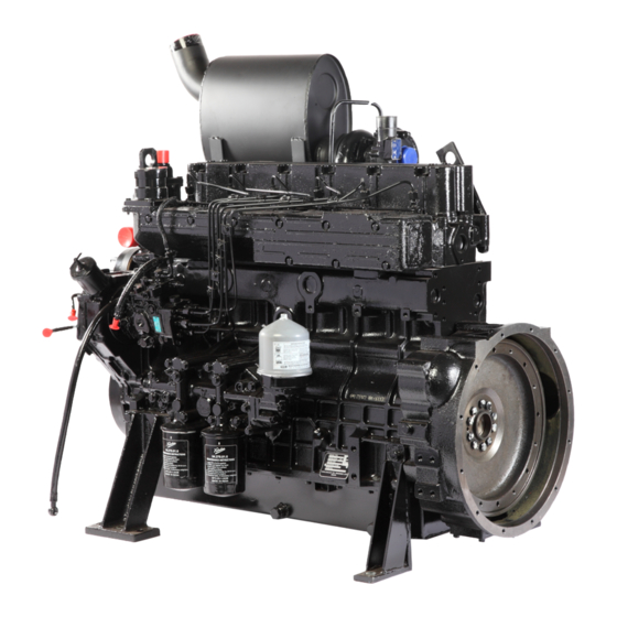
KIRLOSKAR R1040 Maintenance Manual

KIRLOSKAR R1040 Maintenance Manual

Hide thumbs Also See for R1040:
Table of Contents

Advertisement

Sr.
Topic
No.
1
1.1
1.2
1.3
Safety
2
2.1
Engine Name Plate
2.2
2.3
2.4
Lube oil system
2.5
2.6
2.7
3
3.1
Commissioning
3.2
3.3
Stopping
3.4
3.5
Running-in period
4
4.1
4.2
5
Service and Maintenance
5.1
5.2
5.3
5.4
5.5
5.6
5.7
Maintenance of Electrical Equipment
5.8
6
6.1
6.2
6.3
6.4
7
Instruction Manual for Electronic Governor
8
8.1
8.2
8.3
9
9.1
Tightening Torque
9.2
10
Fuel timing
R1040 MAINTENANCE MANUAL

Index

Page 1 of 48
Page
Nos
2
2
2
2
2
2
3
4
5 – 8
9-10
11
12
13-16
16
17
18
19
20
20
21
21
21 - 27
28
29-30
31-34
35
36
37
37
38
38
40
41
41
42
43
43
43
44
45
45
46
47

Advertisement

Table of Contents
loading
Need help?

Need help?

Do you have a question about the R1040 and is the answer not in the manual?

Questions and answers

Summary of Contents for KIRLOSKAR R1040

  • Page 1 R1040 MAINTENANCE MANUAL Index Topic Page General Service and Maintenance Maintenance and Repairs Safety Engine details Engine Name Plate Engine illustrations Engine lifting device Lube oil system 5 – 8 Fuel supply system 9-10 Cooling System Electrical System Engine operation...
  • Page 2 R1040 MAINTENANCE MANUAL 1 General Your engine needs • Clean High Speed Diesel oil. • Lubricating oil of specified quality and viscosity grade. • Fresh air for combustion of fuel, for cooling of engine. • Proper ventilation of engine compartment to avoid re-circulation of hot air.
  • Page 3 R1040 MAINTENANCE MANUAL Engine no is punched on the Name Plate which is fixed on the engine Crankcase. Fig. No 2.1.1 show the engine nameplate 2.2.2 Engine Number System 4H 3002 / 06 00001 Engine serial No Year of Manufacturing Application code No.
  • Page 4 2.3 Engine lifting device 2.3.3 For bare engine for ’R1040/R1080’ Before lifting the engine first fix the lifting hooks on the engine and then lift the engine (see Fig. 2.3.1). The lifting hooks provided on the engine are meant for lifting bare engine only.
  • Page 5 R1040 MAINTENANCE MANUAL Fig. 2.3.1 For Canopied generating set lifting is shown below. Use proper sling/tackle arrangement for lifting the generating set. 2.4 Lube oil system Lube oil circuit Force feed lubrication is provided by a ‘G’ rotor type pump to main bearings, large end bearings, camshaft journals and to the valve gear, fuel pump and turbocharger (incase of turbocharged engines).
  • Page 6 R1040 MAINTENANCE MANUAL Page 6 of 48...
  • Page 7 2.4.5 Lube oil sump capacity and oil change period: - The lube oil sump capacities and oil change period of ‘R1040/R1080’ series engines are as below: - Page 7 of 48...
  • Page 8 R1040 MAINTENANCE MANUAL These capacities are for the standard cast iron and standard sheet metal sumps. Engine type 2R1040 3R1040 4R1040/T/TA 6R1080/T/TA Oil sump type S.M. S.M. S.M. S.M. Initial fill 11.5 (lit.) Refill (lit.) 13.5 Oil Specifications Oil change period (Hours)
  • Page 9 The fuel injection equipment is manufactured to very close tolerances and slightest amount of dirt in fuel can cause wear on the injection equipment. Following points are important in use of fuel on Kirloskar R1040/1080 series engines. The following specifications are approved: - •...
  • Page 10 R1040 MAINTENANCE MANUAL • DIN 51 601 • ASTMD 975-81:1D&2D Winter Grade Fuel- At low temperatures, waxing may occur and clog the fuel system, thus causing operational troubles. In the case of ambient temperature below 10° c, use ‘Winter Grade’ diesel fuel, mixed with Kerosene.
  • Page 11 R1040 MAINTENANCE MANUAL 2.6 Cooling System 2.6.1 Radiator type cooling system The Radiator type cooling system is used. The Schematic diagram, of the typical water circuit with Radiator type cooling system, is Shown in the Fig. 2.6.1 below. Fig. 2.6.1 IMPORTANT •...
  • Page 12 R1040 MAINTENANCE MANUAL Commercially available ready mixed coolants can also be used, with Antifreeze and anticorrosion additives after ascertaining suitability for low ambient temperature. Storage of engine with only fresh water in engine cooling system should be avoided at ambient temperature below 5° C. This may cause cracks in the engine components.
  • Page 13 R1040 MAINTENANCE MANUAL For battery capacity at extreme low temperature i.e. below -20°C, contact your distributor. Battery Cables setting Parameter Cable drop should not exceed than 1.2 V at 600 A. Normal starting current is 600A Based on above two parameters, battery cables are recommended as below...
  • Page 14 R1040 MAINTENANCE MANUAL 3.1.2 Diesel Fill the fuel tank after making sure that it is properly clean. Use High Speed Diesel fuel as recommended in section 2.5.2. According to the ambient temperatures, summer or winter grade diesel fuel should be used. Connect the fuel pump to fuel supply tank as shown in fuel circuit diagram fig.
  • Page 15 R1040 MAINTENANCE MANUAL Tighten the vent screw on primary fuel filter while the diesel fuel id flowing without air bubbles. Similarly bleed the micro filter element by loosening the vent screw on it as shown in fig. 3.1.3.2 above and tighten the vent screw after the removing the air lock.
  • Page 16 R1040 MAINTENANCE MANUAL 3.1.6 Valve Clearance It is not necessary to check adjust the valve clearance on a new engine as it is already adjusted at its required value. However after overhauling the engine, it is necessary to recheck and adjust the valve clearance before starting the engine. See section 5.6.1 3.1.7 Other preparations...
  • Page 17 R1040 MAINTENANCE MANUAL 3.4 Operating conditions 3.4.1 Operation in winter Lube oil viscosity Select specified viscosity grade to meet the performance level for the ambient temperature prevailing at the time of starting the engine. Refer section 2.4.6 Note shorter periods between oil changes when operating below –10 C.
  • Page 18 R1040 MAINTENANCE MANUAL Note: - The declared power ratings of the engine are obtained at standard reference conditions as per ISO 3046/ BS 5514/ DIN 6271/ IS 10000. Where engines are operated at greater altitudes and or higher ambient temperatures, they must be derated in accordance with respective standards.
  • Page 19 R1040 MAINTENANCE MANUAL Deration chart for 4R1040TA/6R1080TA engines The deration chart applicable for 4R1040TA/6R1080TA engines is illustrated below In case of doubt concerning such engine applications, contact your distributor. 3.5 Running in period 3.5.1 After first 100 hours running • Change engine oil and see 5.1.3 •...
  • Page 20 R1040 MAINTENANCE MANUAL 4 Routine Maintenance 4.1 Maintenance Schedule Every In running hours Check Secti- Hour/ Clean Daly Renew 250 400 500 800 1200 2400 3600 Engine oil level 5.1.2 Fuel level in the tank Coolant level in Radiator 5.3.1 Dry type air cleaner 5.4.1...
  • Page 21 R1040 MAINTENANCE MANUAL 4.2 Top Overhaul and Major Overhaul Periods The duration of the operating period before overhaul depend entirely on the maintenance and service given to engine and also the type of environment and engine load cycle. However after about 3000 running hours engine may need top overhaul (servicing of combustion system) and after about 9000 running hours engine may need major overhaul.
  • Page 22 R1040 MAINTENANCE MANUAL IMPORTANT Failure to attend to this may result in serious damage to the engine (piston & bearing seizure) 5.1.3 Changing Engine Oil • Change engine oil at recommended intervals, See 5.1.1 • Run engine until warm.(lube oil temp. approx. 80°C) •...
  • Page 23 R1040 MAINTENANCE MANUAL 5.1.4 Lube oil filter Replace ‘Spin-on’ lube oil filter cartridge for every oil change. • Release lube oil filter cartridge with special tool and spin off as shown in fig. 5.1.4.1 Fig 5.1.4.1 • Clean sealing surface of filter carrier (Fig.5.1.4.2).
  • Page 24 R1040 MAINTENANCE MANUAL • Check oil level and lube oil pressure. • Check seal of lube oil filter cartridge for leaks 5.1.5 Centrifuge Lube oil filter (Applicable for 6R1080T/TA engines) Instruction Manual • Introduction The Centrifuge Cleaner cleans your engine oil continuously when your engine is running.
  • Page 25 R1040 MAINTENANCE MANUAL Fig 5.1.5.2 • Servicing Instructions - It is a precision assembly, handle with care. - Carry out servicing preferably when the engine oil is still warm - All threaded parts of the centrifuge require following gadgets: a 13 mm spanner, a blint knife, a small adjustable pliers and waste cotton for cleaning.
  • Page 26 R1040 MAINTENANCE MANUAL Fig 5.1.5.4 Hold the rotor in hand and lift rotor to remove it completely from central shaft. See Fig 5.1.5.4 above.The rotor will contain about 200 ml of oil. Drain oil from the rotor. The rotor has two bushes at its ends. Take care while removing rotor from central shaft. The rotor should not fall;...
  • Page 27 R1040 MAINTENANCE MANUAL 2. While assembling the rotor, ensure that the rubber ring has taken proper seat in its place. This is necessary for proper sealing of rotor assembly. 3. Take care with the centrifuge housing and rotor body. They are made of aluminium, hence are susceptible to damage due to accident.
  • Page 28 R1040 MAINTENANCE MANUAL Consult your Distributor in case of any doubt. Troubleshooting Problem Probable cause Action Leakage through cleaner Rectangular rubber ring Change rubber ring. damage Rotor does not rotate Nozzles blocked Open rotor and clean nozzles Thoroughly. Re-assemble the cleaner.
  • Page 29 R1040 MAINTENANCE MANUAL • Refit the strainer inside the banjo bolt and screw in the banjo bolt using new copper washers Bleed the fuel system (see 3.1.5) check for leaks • 5.2.2 Fuel Filter • Close fuel stopcock. • Change pre-filter cartridge only. Do not change Pre-filter cartridge and Micro filter cartridge at a time.
  • Page 30 R1040 MAINTENANCE MANUAL Check coolant level in the radiator every day before starting the engine Remove the radiator cap and fill coolant through radiator neck until it spills out of overflow pipe fitted on radiator (Fig.5.3.1). Refit radiator cap firmly.
  • Page 31 R1040 MAINTENANCE MANUAL prevent the rust formation use rust preventive compound. To flush, top up the radiator with clean fresh water and run the engine on no load till it reaches working temperature. • While the engine is still running, open the drain cock of radiator and allow the water to flow out.
  • Page 32 R1040 MAINTENANCE MANUAL Dry type air cleaner with Plastic housing Dry type air cleaner with sheet metal housing Fig 5.4.1 Fig 5.4.2 Inlet cap or pre - cleaner is supplied for the air intake inlet cap prevents ingress of rain/heavy particles.
  • Page 33 R1040 MAINTENANCE MANUAL away from any heavy dust clouds caused by operation. Also, make sure that exhaust carbon cannot enter the air cleaner. Discharge the dust vaccuator valve by pressing apart the lips of the ejection slot, applying pressure as indicated by the arrows See Fig 5.4.2 below.
  • Page 34 R1040 MAINTENANCE MANUAL IMPORTANT Too much air pressure can break the filter paper and destroy the element. (Max. Air Pressure 3.0 kg/cm 2 ) 4) Replace the main element after two cleaning intervals. 5) Rapping, Tapping or Pounding dust out of them is dangerous. Severe damage to the filter will result! 6) Carefully check new or properly cleaned element for damage before installing.
  • Page 35 5.5 Belt drives A single V belt of NPA/XPA section is used to drive engine water pump, radiator fan and battery charging alternator for R1040/3R1040/4R1040/4R1040T engines. • Inspect V-belts over whole length for damage or cracks. Renew damaged or cracked v- belts.
  • Page 36 R1040 MAINTENANCE MANUAL tension with the help of tension adjusting screw provided on the fan driving arrangement. 5.6 Adjustments 5.6.1 Checking and adjusting valve clearance The valve clearance is the requisite gap between the rocker arm toe and valve stem end. See Fig 5.6.1 below.
  • Page 37 R1040 MAINTENANCE MANUAL Fig 5.6.2 • Similarly, check the valve clearance of exhaust valve with 0.3mm feeler gauge. Readjust if necessary. Check the valve clearances of each of the remaining cylinders and readjust, if necessary • • Do not change the setting of oil metering screw unless required. With hot engine running at idling, an oil flow to pad at rocker arm must be just noticeable.
  • Page 38 R1040 MAINTENANCE MANUAL • Check the commutator surface. It should be clean and entirely free from oil, any trace of which should be removed by pressing a dry fluff less cloth against the commutator while the armature is hand rotated. It the surface is dirty or badly discolored, clean it with a strip of fine emery.
  • Page 39 R1040 MAINTENANCE MANUAL In the event of trouble, always check whether the operating and maintenance • instructions have been strictly followed. • An appropriate diagnosis chart is given on the next page. • If you are unable to identify the cause of the trouble or to put it right yourself, contact your Distributor 6.1 Troubleshooting...
  • Page 40 R1040 MAINTENANCE MANUAL engine Mis setting of valve air gaps Adjust correct valve air gaps Mechanical defects of engine Consult your Distributor Engine grows Slipping of V-belts Tighten or replace V-belts excessively hot V-belts broken Replace V-belts Defect of temperature governor Emergency operation;...
  • Page 41 R1040 MAINTENANCE MANUAL Heavy blowing from Excessively high lube oil level, Adjust oil level. Consult your venting hose of damages of cylinder elements Distributor engine No air supply from Defect of cylinder element or of Consult your Distributor piston or compressor...
  • Page 42 R1040 MAINTENANCE MANUAL 6.4 Recommendation for Turbocharger operation and maintenance Operation Recommendations Engine should not be put under full load immediately after start. We recommend the engine to be run at idling speed for a short time (60 seconds). Warm up the engine under medium load.
  • Page 43 R1040 MAINTENANCE MANUAL Electronic Governor The Electronic Governor consists of three components. Electric Actuator - Connected to engine fuel pump & controls the fuel quantity delivered to the engine. Electronic Speed Control Unit - Compares the existing engine speed with desired speed &...
  • Page 44 R1040 MAINTENANCE MANUAL Should normal values be indicated during troubleshooting steps, then the fault may be with the actuator or the wiring to the actuator. Tests are performed with the battery power on, engine off except where noted. See actuator publication for testing details...
  • Page 45 R1040 MAINTENANCE MANUAL the engine using decompressor lever, till it fires) and let it run for 30 seconds. During this time the diesel in fuel pump gallery and high pressure pipes will be displaced by Diesel + Preservative Oil mixture. Stop the engine.
  • Page 46 R1040 MAINTENANCE MANUAL 9 Tightening Torque, Settings Tightening Torque To prevent faulty assembly, following information on tightening of high tensile bolts is important. The bolts are to be tightened in stages as specified in the table below. For connecting rod bolt and main bearing cap bolt use angle torque method with the help of goniometer.
  • Page 47 R1040 MAINTENANCE MANUAL (M12x1.75x60mm long 10.9) Bolt for main bearing cap (M14x2x128 mm long 10.9) Bolt for Connecting rod (M12x1.5x55mm long 10.9) Bolt for Crank pulley (M24x2x100 mm long 10.9) without power take off Bolt for flywheel (M10x1x45mm long 10.9) Bolt for flywheel housing (M10x1.5x40mm long 10.9)
  • Page 48 R1040 MAINTENANCE MANUAL A provision for locking the engine at fuel timing is provided with the help of locking pin and corresponding hole on the flywheel. • Bring the engine near firing TDC position and Lock the engine at fuel timing by using the locking pin as shown.

This manual is also suitable for:

2r10403r10404r1040t4r1040ta6r1080t6r1080ta

Table of Contents

Save PDF