Table of Contents
Advertisement
Quick Links
Advertisement
Table of Contents

Related Manuals for MMF VM24


Summary of Contents for MMF VM24
- Page 1 Instruction Manual Vibration Meter VM24 Valid from Version xxx.021 Manfred Weber Metra Mess- und Frequenztechnik in Radebeul e.K. Meissner Str. 58 - D-01445 Radebeul Tel. +49-351 836 2191 Fax +49-351 836 2940 Email: Info@MMF.de Internet: www.MMF.de...
- Page 2 Manfred Weber Metra Mess- und Frequenztechnik in Radebeul e.K. Meißner Str. 58 D-01445 Radebeul Tel. +49-351-836 2191 +49-351-836 2940 Email Info@MMF.de Internet www.MMF.de Note: The latest version of this manual can be found at http://www.mmf.de/prod- uct_literature.htm Specification subject to change.
-
Page 3: Table Of Contents
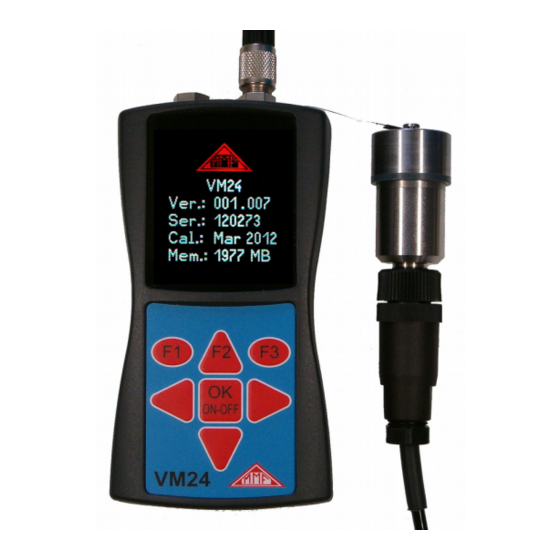
6. Measurement......................14 6.1. Measurement Value Display................14 6.2. Selecting the Display Quantity..............14 6.3. Measurement Point Detection..............15 6.3.1. Reading the VMID Data with the VM24..........15 6.3.2. Entering the Measurement Point Text..........15 6.3.3. Editing and Deleting Measurement Point Data........17 6.4. Saving Measurands..................17 6.5. Graphical Trend Display................17 6.6. - Page 4 Figure 1: VM24 with Sensor...
-
Page 5: Purpose
In the development of the VM24 value was placed on simple operation and mainte- nance requirements, which enable trained personnel to operate the instrument with- out the need of being specially qualified. -
Page 6: The Measuring Instrument
Figure 2: Block Diagram 2 shows the block diagram. The VM24 supplies the IEPE Sensor with 2 mA con- stant current. At the sensor output, a vibration acceleration proportional AC voltage arises, which is amplified in the instrument to produce an optimum level. The gain switch-over takes place automatically. -
Page 7: Vibration Acceleration
2.8 s 2.930 kHz 3.2. Vibration Acceleration The VM24 has the following frequency ranges for vibration acceleration: • 0.2 Hz to 10 kHz: full frequency bandwidth of the accelerometer • 3 Hz to 1 kHz: lower frequency acceleration • 1 kHz to 10 kHz: high frequency vibration only In this way specific signal components can be measured whilst others are attenu - ated. - Page 8 Besides the frequency range of 10 to 1000 Hz, the VM24 has a further frequency range for vibration severity measurements from 2 to 1000 Hz. This is suitable for measurements on slow running machines with a nominal speed of less than 120 min and on reciprocating engines according to ISO 10816-6.
-
Page 9: Vibration Displacement
The VM24 measures the vibration displacement from 5 to 200 Hz. The frequency re- sponse diagram is shown in 6. The curve ends at 200 Hz because even in the case of a fully modulated sensor only single digit measurement values still occur. -
Page 10: The Batteries
1000 Figure 7: Frequency response curves for displacement (RMS) The maximum displacement of the VM24 that can be measured is around 60 mm (RMS). It yields a frequency independent modulation range of up to 10 Hz. At higher frequencies the measuring range limits for acceleration of around 240 m/s² take effect. -
Page 11: Switching On And Off
Figure 8: Battery Compartment Important: • Always use three batteries of the same type and same date of manufacture. • Remove old batteries from the instrument, and take out the batteries if the instru- ment will not be used for a long period of time. Otherwise leaking battery acid may cause severe damage to the instrument. -
Page 12: Battery Display And Battery Type
At this point the battery level indicator is completely empty and the instrument switches itself off automatically. If the VM24 is connected to a USB port, it will be supplied by the USB voltage in order to spare the batteries. In this case, “external” is displayed on the screen instead... -
Page 13: Shut-Off Timer
4.4. Shut-off Timer The VM24 has a shut-off timer to help prolong the battery operating life. To set the shut-off timer, open the main menu by pressing F3. Scroll down into the sub-menu 'Instrument Settings' by pressing▼and OK, and within this sub-menu select the menu option “Shut off Timer”. - Page 14 The Standard ISO 13373-1 also gives recommendations for measurement points on various machine type. Figure 13: Measuring points on vertical Figure 14: Measuring points on flange bearings bearings Figure 15: Measuring points on electric motors Figure 16: Measuring points on ma- chines with vertical rotors...
-
Page 15: Vmid Measurement Point
5.3. VMID Measurement Point 5.3.1. How the VMID Measurement Point Functions The VM24 is equipped with an electronic measuring point detector. Metra offers a type VMID measurement point, which is made of magnetic stainless steel and has an inbuilt memory with an individual serial number (17). -
Page 16: Measurement
Note: When saving measurement values (chapter 6.4) the RMS and peak value are always saved irrespective of the currently selected setting. If the sensor locates a VMID measuring point which is already saved in the VM24 memory, in order to prevent unintentional switch-over, a warning signal will be dis- played when the measurand changes (19). -
Page 17: Measurement Point Detection
As soon as the Sensor base comes into contact with the measurement point, the VM24 displays the measurement point number (Point ID) (20). Figure 20: Newly recognized VMID 6.3.2. Entering the Measurement Point Text If a measurement point has not yet been assigned a text, press the▼... - Page 18 Figure 22: ID text display Once you have assigned the VMID serial number a text, the VM24 will display the text continually, as soon as the sensor makes contact with the measuring point (22). Aside from this, the VM24 reverts automatically to the saved operation mode. In this way it is ensured that measurements are always taken with the correct settings.
-
Page 19: Editing And Deleting Measurement Point Data
In the same way, the entire measurement point data can be deleted as a whole by se - lecting “Erase all Point IDs” in the “ID Menu”. The VM24 memory can store data for a maximum of 1600 measurement points. -
Page 20: Viewing Saved Measurement Values
To deliver the service staff on site a report about the periodic changes in vibration severity and consequently the previous history of the measurement point concerned, the VM24 provides a graphical trend display. The prerequisite for retrieving graph- ical trends is placing the sensor on the relevant VMID. The trend display is obtained by pressing the F1 key (24). -
Page 21: Deleting Saved Measurement Data
Press ▼▲ to scroll to the next measurand. The currently displayed measurands can be deleted by pressing F1. Press F3 to exit the menu. The VM24 memory can hold 16000 measurement values. 6.7. Deleting Saved Measurement Data In the menu option “Measurement data” / “Erase meas. data Memory” you can delete the entire measurement data. - Page 22 A: New condition B: Good condition for unrestricted continuous operation C: Poor condition - allows restricted continued operation only D: Critical condition - Danger of damage to the machine. 45 mm/s 28 mm/s 18 mm/s 14.7 mm/s Zone 11.2 mm/s 4,5 –...
- Page 23 In part 3 of ISO 10816, revised in 2009, the zone borders are specified for vibration severity of machines with a power of 15 kW to 50 MW ( 2). Medium sized ma- Large machines with chines with 15 to 300 300 kW to 50 MW Machine type Electric motors with a...
-
Page 24: Setting The Date And Time
Part 7 of the ISO 10816 deals specifically with rotodynamic pumps (3). Category 1 Category 2 Pumps with high Pumps for general Type safety and reliability and less critical use demands Performance < 200 kW > 200 kW < 200 kW >... -
Page 25: Calibration
To exit the menu press OK followed by F3 repeatedly. 9. Calibration The VM24 comes with with a factory calibration, which is traceable to the reference standard of the Physikalisch-Technischen Bundesanstalt (PTB). The calibration is only valid with the supplied vibration transducer. The serial number of the instru - ment and the transducer are stated on the calibration certificate. - Page 26 You will be requested to mount the sensor on to the vibration exciter (29). This is done using the magnetic base. Press OK. Figure 29: Calibration menu The VM24 is now ready for the reference vibration signal. It displays the measured acceleration (30). Figure 30: Calibration...
-
Page 27: Sensor Check
ERROR” instead of the measurand. 11. Reset Key If it occurs that the VM24 does not respond to the press of any button, press the re- set key to restart the instrument. The reset key is reached with a thin object through the aperture next to the type label (31). -
Page 28: Connection To A Pc
12. Connection to a PC 12.1. Device Driver The VM24 has a USB port. For connection to a PC the VM2x USB cable is pro - vided (32), which is connected to the 8 pin socket on the VM24. Switch the instru - ment off before connecting it to the PC. -
Page 29: Firmware Update
Figure 33: VM2x Measurement Database The program is available for downloading at http://www.mmf.de/software_download.ht m#vm2x A sample record can be used to get familiar with the functions. For more detailed information a help function is provided. 12.3. Firmware Update The instrument software (Firmware) can be updated via the USB port. First of all, check whether a more up-to-date version than currently installed is available. - Page 30 2. Also download the program “Firmware Updater” from the above named inter- net address and install it on your PC. 3. Connect the VM24 to the PC using the USB cable and switch it on so that Win- dows detects it as USB device.
- Page 31 The transfer progress is displayed as a time bar on the PC ans also on the VM24. When the update is finished the VM24 will start up and the “Firmware Updater” will close. Please do not interrupt the update process. Fol- lowing transfer failures the update can be restarted at point 3.
-
Page 32: Technical Data
13. Technical Data Displayed measurand True RMS and peak value (crest value) of vibration acceler- ation, velocity and and displacement Measuring range Acceleration: 0.1 – 240 m/s² at defined accuracy Velocity: 0.1 – 1000 mm/s; > 40 Hz frequency dependent Displacement: 0.01 –... - Page 33 Coding 16 digit unique hexadecimal number Measuring point ID mem- 1600 measuring points with serial number and text ory (VM24) Mounting the VMID Mount with two part adhesive, e.g. LOCTITE Hysol 3430 or 3450 Maximum temperature 80 °C...
-
Page 34: Declaration Of Ce Conformity
The repaired or replaced product will be sent back at Metra’s expense. Declaration of Conformity According to EMC Directive 2014/30/EC Product: Vibration Meter Type: VM24 (from Ser. no. 160000) It is hereby certified that the above mentioned product complies with the demands pursuant to the following standards: DIN EN 61326-1: 2013...
Need help?
Do you have a question about the VM24 and is the answer not in the manual?
Questions and answers