Table of Contents
Advertisement
Quick Links
Advertisement
Table of Contents

Related Manuals for MMF VM25


Summary of Contents for MMF VM25
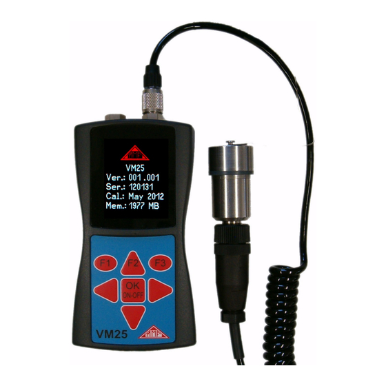
- Page 1 Instruction Manual Vibration Meter VM25 Valid from Version 001.009 Manfred Weber Metra Mess- und Frequenztechnik in Radebeul e.K. Meissner Str. 58 - D-01445 Radebeul Tel. +49-351 836 2191 Fax +49-351 836 2940 Email: Info@MMF.de Internet: www.MMF.de...
- Page 2 Metra Mess- und Frequenztechnik in Radebeul e.K. Meißner Str. 58 D-01445 Radebeul Tel. +49-351-836 2191 +49-351-836 2940 Email Info@MMF.de Internet www.MMF.de Note: The latest version of this manual can be found at http://www.mmf.de/product_literature.htm Specification subject to change. © 2012 Manfred Weber Metra Mess- und Frequenztechnik in Radebeul e.K.
-
Page 3: Table Of Contents
6. Measurement.......................15 6.1. Measurement Value Display.................15 6.2. Selecting the Display Quantity..............15 6.3. Measurement Point Detection...............16 6.3.1. Reading the VMID Data with the VM25..........16 6.3.2. Entering the Measurement Point Text...........16 6.3.3. Editing and Deleting Measurement Point Data........18 6.4. Saving Measurands..................18 6.5. Graphical Trend Display................18 6.6. - Page 4 13. Connection to a PC....................33 13.1. Device Driver.....................33 13.2. VM2x Measurement Database..............34 13.3. Export of FFT Data to a PC................35 13.4. Firmware Update..................36 14. Technical Data....................38 Limited Warranty....................40 Figure 1: VM25 with vibration sensor...
-
Page 5: Purpose
In the development of the VM25 value was placed on simple operation and mainte- nance requirements, which enable trained personnel to operate the instrument with - out the need of being specially qualified. -
Page 6: The Measuring Instrument
Figure 2: Block Diagram Figure 2 shows the block diagram. The VM25 supplies the IEPE Sensor with 2 mA constant current. At the sensor output, a vibration acceleration proportional AC volt- age arises, which is amplified in the instrument to produce an optimum level. The gain switch-over takes place automatically. -
Page 7: Vibration Acceleration
2.8 s 2.930 kHz 3.2. Vibration Acceleration The VM25 has the following frequency ranges for vibration acceleration: • 0.2 Hz to 10 kHz: full frequency bandwidth of the accelerometer • 3 Hz to 1 kHz: lower frequency acceleration • 1 kHz to 10 kHz: high frequency vibration only In this way specific signal components can be measured whilst others are attenuated. - Page 8 Besides the frequency range of 10 to 1000 Hz, the VM25 has a further frequency range for vibration severity measurements from 2 to 1000 Hz. This is suitable for measurements on slow running machines with a nominal speed of less than 120 min and on reciprocating engines according to ISO 10816-6.
-
Page 9: Vibration Displacement
The VM25 measures the vibration displacement from 5 to 200 Hz. The frequency re- sponse diagram is shown in Figure 6. The curve ends at 200 Hz because even in the case of a fully modulated sensor only single digit measurement values still occur. -
Page 10: Rolling Bearing Parameters K(T)
1000 Figure 7: Frequency response curves for displacement (RMS) The maximum displacement of the VM25 that can be measured is around 60 mm (RMS). It yields a frequency independent modulation range of up to 10 Hz. At higher frequencies the measuring range limits for acceleration of around 240 m/s² take effect. -
Page 11: Rotational Speed
3.6. Rotational Speed Alongside vibration the VM25 measures the rotational speed by means of an inbuilt contactless optical sensor (Figure 34 on page 25). To enable this, the instrument needs to be aligned with the rotating part, for which a laser pointer can be used to help with the positioning. -
Page 12: Switching On And Off
To insert the batteries, remove the two screws from the back cover of the device and open the battery compartment (Figure 8). When inserting the batteries, please ensure that their polarity is correct, (see the engraved markings inside the compartment). Figure 8: Battery Compartment Important: •... -
Page 13: Battery Display And Battery Type
At this point the battery level indicator is completely empty and the instrument switches itself off automatically. If the VM25 is connected to a USB port, it will be supplied by the USB voltage in order to spare the batteries. In this case, “external” is displayed on the screen instead... -
Page 14: Shut-Off Timer
4.4. Shut-off Timer The VM25 has a shut-off timer to help prolong the battery operating life. To set the shut-off timer, open the main menu by pressing F3. Scroll down into the sub-menu 'Instrument Settings' by pressing▼and OK, and within this sub-menu select the menu option “Shut off Timer”. - Page 15 The following illustrations give a few examples of suitable measurement point loca- tions.. The Standard ISO 13373-1 also gives recommendations for measurement points on various machine type. Figure 14: Measuring points on flange Figure 13: Measuring points on vertical bearings bearings Figure 15: Measuring points on electric motors...
-
Page 16: Vmid Measurement Point
5.3. VMID Measurement Point 5.3.1. How the VMID Measurement Point Functions The VM25 is equipped with an electronic measuring point detector. Metra offers a type VMID measurement point, which is made of magnetic stainless steel and has an inbuilt memory with an individual serial number (Figure 17). -
Page 17: Measurement
6. Measurement 6.1. Measurement Value Display In the top margin of the screen (Figure 18) the battery power is displayed. Next to this the date and time are also indicated.. Figure 18: Measurement display Below the measurand (v: 10 Hz-1 kHz RMS) the currently measured value. The display “No Point ID”... -
Page 18: Measurement Point Detection
If the sensor locates a VMID measuring point which is already saved in the VM25 memory, in order to prevent unintentional switch-over, a warning signal will be dis- played when the measurand changes (Figure 19). By pressing OK the measuring range can still be changed. - Page 19 Note: More conveniently, the measurement point texts can also be entered using the available computer software. Figure 22: ID text display Once you have assigned the VMID serial number a text, the VM25 will display the text continually, as soon as the sensor makes contact with the measuring point (Fig- ure 22).
-
Page 20: Editing And Deleting Measurement Point Data
In the same way, the entire measurement point data can be deleted as a whole by se - lecting “Erase all Point IDs” in the “ID Menu”. The VM25 memory can store data for a maximum of 1600 measurement points. -
Page 21: Viewing Saved Measurement Values
To deliver the service staff on site a report about the periodic changes in vibration severity and consequently the previous history of the measurement point concerned, the VM25 provides a graphical trend display. The prerequisite for retrieving graphi- cal trends is placing the sensor on the relevant VMID. The trend display is obtained by pressing the F1 key (Figure 24). -
Page 22: Deleting Saved Measurement Data
Place the sensor on a VMID measuring point of the relevant bearing. If the VMID measurement point ID has not yet been saved in the VM25 (Figure 27), then first of all enter the ID name by pressing the ▼ key (cf. Section 6.3.2). - Page 23 Figure 27: K(t) mode with newly detected VMID If the VMID point ID has been saved but not the K(t) start values, then this is the next step. By pressing the ▼ key the currently measured RMS RMS(t) and peak value Peak(t) are saved as K(t) the start value RMS(0) and Peak(0) (Figure 28).
- Page 24 Figure 29: K(t)-display To view or delete the saved K(t) start values open the menu “K(t) base memory” (Figure 30). In the sub-menu “View K(t) base memory” you can scroll through the saved start values using the ▼▲ keys. Press F1 to delete an entry. In the sub-menu “Erase K(t) memory”...
-
Page 25: Frequency Analysis
Settings 6.9.1. In addition to the measurement of RMS and peak values the VM25 has a simple fre- quency analysis function. To access this function, switch to the main menu by press- ing F3 and select the menu option “Frequency analysis (Figure 31). -
Page 26: Fft Memory
The left end of the frequency axis always represents 0 Hz. However, the 0 Hz line and for velocity also the next line are not displayed to suppress DC and low noise errors. The line above the diagram shows magnitude and frequency of the main spectral line. -
Page 27: Rotation Speed Measurement
6.10. Rotation Speed Measurement The VM25 has an inbuilt RPM laser sensor for contactless measurements. This is lo- cated in the lower part at the back of the instrument (Figure 34). Figure 34: Rotation speed and temperature sensor, laser pointer For taking rotation speed measurements the rotating part needs to be marked with a piece of reflective film. -
Page 28: Temperature Measurement
Set the instrument up on the measuring point, without covering the light beam range with your fingers. To help with the positioning, the VM25 has a laser pointer which can be switched on and off by pressing F1. Caution: The laser beam has a radiation power of < 1 mW at 650 nm wavelength. -
Page 29: Measurement Evaluation With Standard Values
7. Measurement Evaluation with Standard Values To be able to derive statements from the measured vibration velocity values about the condition of a machine, experience is necessary. If experienced personnel are not available, in many cases one can refer to the ISO 10816 recommendations. In these sections of the standard, the vibration severity zone limits for various machine types are defined, which can provide an initial evaluation of a machines maintenance con- dition. - Page 30 In part 3 of ISO 10816, revised in 2009, the zone borders are specified for vibration severity of machines with a power of 15 kW to 50 MW (Table 2). Medium sized ma- Large machines with chines with 15 to 300 300 kW to 50 MW Machine type Electric motors with a...
-
Page 31: Setting The Date And Time
Part 7 of the ISO 10816 deals specifically with rotodynamic pumps (Table 3). Category 1 Category 2 Pumps with high Pumps for general Type safety and reliability and less critical use demands Performance < 200 kW > 200 kW < 200 kW >... -
Page 32: Calibration
To exit the menu press OK followed by F3 repeatedly. 9. Calibration The VM25 comes with with a factory calibration, which is traceable to the reference standard of the Physikalisch-Technischen Bundesanstalt (PTB). The calibration is only valid with the supplied vibration transducer. The serial number of the instru- ment and the transducer are stated on the calibration certificate. - Page 33 You will be requested to mount the sensor on to the vibration exciter (Figure 40). This is done using the magnetic base. Press OK. Figure 40: Calibration menu The VM25 is now ready for the reference vibration signal. It displays the measured acceleration (Figure 41). Figure 41: Calibration...
-
Page 34: Sensor Check
10.00 mm/s s. 10. Sensor Check The VM25 input is designed for use with a low power IEPE accelerometer. These sensors are supplied by constant current, which produces a positive DC voltage po- tential at the output. Due to this DC voltage an assessment can be made of the sen - sor's operating condition. -
Page 35: Reset Key
12. Reset Key If it occurs that the VM25 does not respond to the press of any button, press the re - set key to restart the instrument. The reset key is reached with a thin object through the aperture next to the type label (Figure 45). -
Page 36: Vm2X Measurement Database
Connect the other end of the cable to a USB port of the computer and switch the VM25 on again. If the instrument is being connected with a particular computer for the first time, a driver installation will be necessary. The driver MMF_VCP.zip can be found on our website: http://mmf.de/software_download.htm... -
Page 37: Export Of Fft Data To A Pc
Figure 47: VM2x Measurement Database The program is available for downloading at http://www.mmf.de/software_download.ht m#vm2x A sample record can be used to get familiar with the functions. For more detailed information a help function is provided. 13.3. Export of FFT Data to a PC A tool for exporting the stored FFT data can be found at http://www.mmf.de/software_download.ht m#vm2x... -
Page 38: Firmware Update
To view the latest version visit our 'Software Download' site. http://www.mmf.de/software-download.htm Here you will see the most recent firmware version available. The version number is composed of three digits for the hardware and three for the software (hhh.sss). Only the last three digits are relevant for the firmware. - Page 39 6. Within the VM25 “Instrument Settings” select the option “Update Firmware” and confirm the warning and subsequent hint messages by pressing OK. By car- rying out this step the old firmware is deleted. The VM25 will then indicate that it awaits new firmware data from the USB port (Figure 51).
-
Page 40: Technical Data
14. Technical Data Displayed measurand True RMS and peak value (crest value) of vibration acceler- ation, velocity and displacement, K(t) rolling bearing parameters, rotation speed, temperature Measuring range Acceleration: 0.1 – 240 m/s² at defined accuracy Velocity: 0.1 – 1000 mm/s; > 40 Hz frequency dependent Displacement: 0.01 –... - Page 41 Coding 16 digit unique hexadecimal number Measuring point ID mem- 1600 measuring points with serial number and text ory (VM25) Mounting the VMID Mount with two part adhesive, e.g. LOCTITE Hysol 3430 or 3450 Maximum temperature 80 °C...
-
Page 42: Limited Warranty
The repaired or replaced product will be sent back at Metra’s expense. Declaration of Conformity According to EMC Directive 2014/30/EC Product: Vibration Meter Type: VM25 (from Ser. no. 160000) It is hereby certified that the above mentioned product complies with the demands pursuant to the following standards: DIN EN 61326-1: 2013...
Need help?
Do you have a question about the VM25 and is the answer not in the manual?
Questions and answers