
Related Manuals for Wise GM-1000


Summary of Contents for Wise GM-1000
- Page 1 Bar Graph Indicator GM-1000 VER 3.2 '06. 01 Instruction Manual WISE CONTROL, GED http://www.wisegas.com...
-
Page 2: Table Of Contents
www.DataSheet4U.com Contents 1. Important Remarks………………………………………………………………………..3 2. Introduction…………………………………………………………………………………...4 3. Characteristics………………………………………………………………………………..5 4. Specifications………………………….………………………...……………………………6 5. Installation……………………………….……………………………………………………7 5.1 Main instrument installation…..………………………………………………………..7 6. Wiring…………………………………….……………………………………………………8 6.1 Power…………………………………………………………………………………….8 6.2 Single case wiring……………………………………………………………………….8 6.3 Multi-unit case wiring.…………………………………………………………………9 6.4 The connection with a common alarm unit.…………………………………………10 6.5 The select of sensor and signal source.…………………………………………….11 6.6 Alarm output…………………………….……………………………………………...13 6.7 Connection of retransmittion signal…………………..……………………………...13 6.8 Earth……….…………………………….……………………………………………...13... -
Page 3: Important Remarks
/or not conforming to standards and regulations in force. ▷WISE CONTROL does not allow or authorize any company, person or legal entity to assume such responsibility on the part of WISE CONTROL, even if involved in the sale of the product of WISE CONTROL. -
Page 4: Introduction
GM-1000 is installed at the place using gases by raw materials, supplying gases or the place can be leak gas, like industrial areas, gas charging sites, petrochemical plants, chemical plants, etc. And it can protect industrial calamity by detecting gas leakage and notifying in advance. -
Page 5: Characteristics
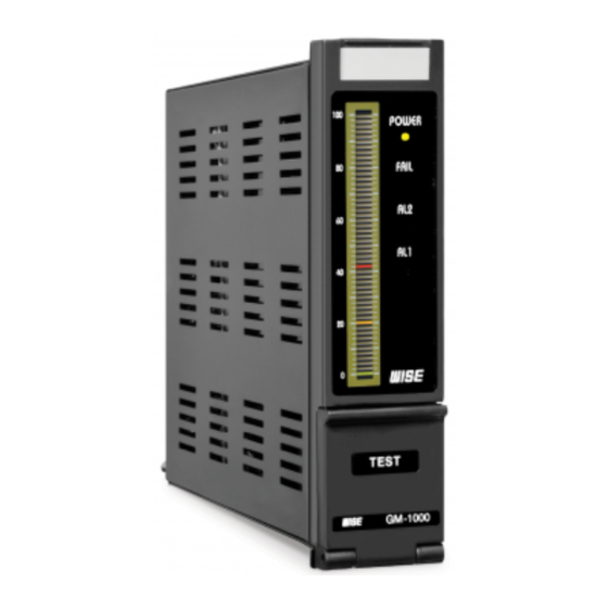
■ GM-1000 is installed at the place using gases by raw materials, supplying gases or the place can be leak gas, like industrial areas, gas charging sites, petrochemical plants, chemical plants, etc. And it can protect industrial calamity by detecting gas leakage and notifying in advance. - Page 6 www.DataSheet4U.com Display 51 segment bar graphic 3 Color Changeable Bar Power, Fail, Al1 and Al2 graphic Sensor input Selectable Measuring Range 0 ~ 100% LEL or Depending on the gas Alarm Set Point Two (High, High-High) L, LL available Set Value 0 to F.S.
-
Page 7: Installation
α = 2 n= 6∼10 : • • • • • • α = 3 n= 11∼15 : n: amount of indicator and alarm unit (36 × n – 3) + α Fig. 5.1 The shape of GM-1000, Panel cut... -
Page 8: Wiring
www.DataSheet4U.com 6. Wiring 6.1 Power After certify the power for using is the same as the power that designate in wiring diagram, you may wire. In order to protect a surge, you may separate an instrument power and a power line (operation power of heater, magnet S/W) 6.2 Single case wiring Fig. -
Page 9: Multi-Unit Case Wiring
▶ Non Transmitter type(Sensor type) CASE1 – 4-wire type sensor CASE2 – 3-wire type sensor ▶ Transmitter type CASE3 – Transmitter type 3-wire CASE4 – Transmitter type 2-wire Fig. 6.2 The wiring method of GM-1000 single case and the wiring diagram. -
Page 10: The Connection With A Common Alarm Unit
Notice) When you connect a ribbon cable, you may off the power of instrument. If you put on/off the cable when the power is loaded, then the electronic circuit can be destroyed Indicator (GM-1000) Alarm unit (AM-2000) Individual Power S/W... -
Page 11: The Select Of Sensor And Signal Source
www.DataSheet4U.com 6.5 The select of sensor and signal source 6.5.1 local detector (diffusion type combustible detector) 1) You may release the lock screw of detector and pull out an instrument from the case carefully. 2) After you off the power, you may connect the connector between a detector and a terminal. 3) You may select the input select jumper on a back lower of connector to the connecting point of combustible gas sensor (refer to Fig. - Page 12 www.DataSheet4U.com area of wire like below. ⊙ In case of 1.25 mm SQUARE: about 1.2 Km ⊙ In case of 2.0 mm SQUARE: about 2.0 Km ⊙ In case of 3.5 mm SQUARE: about 4.0 Km Notice) Cross section areas of four sensor extension wire must be same 6.5.2 Local detector (Suction type combustible gas detector) 1) The connection of sensor is the same as diffusion type combustible gas detector.
-
Page 13: Alarm Output
www.DataSheet4U.com 6.6 Alarm output The three point of alarm contact output are offered. 6.6.1 Connection of danger alarm output (AL2 alarm output) ⊙ C (COMMON) of alarm output #2 : connect to terminal #16 ⊙ NO (NORMAL OPEN ) of alarm output #2 : connect to terminal #11 ⊙... -
Page 14: Operation
7. Operation 7.1 Names and functions of GM-1000 ⑨ ⑩ ⑪ ⑫ ⑬ ① ④ ⑤ ⑥ ⑦ ② ③ ⑧ ⑰ ⑯ ⑭ ⑮ Name Function Name Function Transmitter type NAME PLATE Write TAG No. 4-20mA ZERO VR... -
Page 15: Operation Mode
www.DataSheet4U.com 7.3 Operation mode 7.3.1 Sensor stabilization time (WARMM-UP) You have to wait for sensor stabilization time because a detector does not act immediately. At this time, the value from 0 to 100 %LEL are indicated for 30 second. (Sensor stabilization time) 1) Alarm output does not brake out. - Page 16 www.DataSheet4U.com After you saturated point, you may set the indicated value to 50 by SPAN VR. Ⅱ. Transmitter (2,3-wire type) 1) After 4 mA is supplied by a current source, you set the zero point by the Zero VR. 2) After 12 mA is supplied by a current source, you set the 50 point by the Span VR. 3) You do not need to calibrate the setting because setting points are calibrated when products are shipped.
- Page 17 www.DataSheet4U.com 7.3.6 Alarm acted state During the normal state, gas leakage alarm state and normal state again, lamp and buzzer of alarm state is like below. AL2 SET POINT AL1 SET POINT AL1-LAMP AL2-LAMP AL1-RELAY AL2-RELAY BUZZER BUZZER STOP RESET 7.3.7 Sensor trouble alarm In case of that sensor is damaged or lead wire is disconnected by connection of combustible gas sensor.
- Page 18 www.DataSheet4U.com 7.3.9 Power voltage insufficiency If the power supply voltage is decreased to 18 VDC, then ⊙ detector will be stop. ⊙ all alarm contact output will be off. ⊙ transmitter output does not tout (0 mA) ⊙ You supply normal power again, then the instrument is operated normally after sensor stabilization time.
-
Page 19: Others
** In order to improve the product, the above statements can be modified without a previous notice. WISECONTROL INC & SYSTEM ENGINEERING GED JAN. 2006 VERSION 3.2 WISE CONTROL INC. 199 Sanggal-dong, Giheung-gu, Yongin-city, Kyunggi-do, Korea (449-905) TEL : +82-31-283-5030/2 FAX : +82-31-283-2152 Web site: http://www.wisegas.com...
Need help?
Do you have a question about the GM-1000 and is the answer not in the manual?
Questions and answers