
Subscribe to Our Youtube Channel
Related Manuals for TEXIO LW Series


Summary of Contents for TEXIO LW Series
- Page 1 INSTRUCTION MANUAL MULTI-INPUT ELECTONIC LOADING UNITS LW SERIES LW75-151Q LW151-151D LW75-151D LW301-151S EXTERNAL INTERFACE UNITS IF-50GP IF-50USB © PRINTED IN JAPAN B71-0006-00...
- Page 3 SAFETY ● Symbol in This Manual This symbol indicates where applicable cautionary or other information is to be found. ● Power Source This equipment operates from a power source that does not apply more than 250V rms between the supply conductors or between both supply conductor and ground. A protective ground connection by way of the grounding conductor in the power cord is essential for safe operation.
-
Page 4: Table Of Contents
TABLE OF CONTENTS SAFETY 1. ABOUT THIS PRODUCT........................1 1-1 About This Manual..........................1 1-2 Product Overview ..........................1 1-3 Features............................1 1-3-1 LW electronic loading unit......................1 1-3-2 IF-50GP (Option) ........................2 1-3-3 IF-50USB (Option)........................2 2. SPECIFICATIONS..........................3 2-1 aximum Input Rating......................... - Page 5 4. PANELS ..............................11 4-1 Front Panel ............................11 4-2 Rear Panel............................15 4-3 Optional Board Mount ........................17 5. BEFORE USING UNIT......................... 18 5-1 Position of Voltage Remote Sensing Selector Switches..............18 5-2 Connection of Power Supply......................19 5-2-1 Connecting with input terminals on front panel ............... 19 5-2-2 Connecting with input terminals on rear panel ................
- Page 6 6-2-11 Increasing and decreasing set values of CR mode............... 37 6-2-12 Setting CR mode value by means of voltage and current setting......... 39 6-2-13 Increasing and decreasing current limit set value..............40 6-3 Memory Functions ........................41 6-3-1 Storing preset values (discharge mode and set value) in EEPROM ........41 6-3-2 Storing key settings in EEPROM.....................
- Page 7 8. EXTERNAL VOLTAGE CONTROL ..................... 57 8-1 Pins for External Voltage Control ....................57 8-1-1 Specifications of J2........................57 8-1-2 Connecting external voltage source and J2 ................57 8-1-3 Specifications of controls......................58 8-2 Usage of External Voltage Control Function .................. 58 8-2-1 Checking set value of external voltage control................
- Page 8 10-1-9 Saving preset data in EEPROM .................... 71 10-1-10 Turning on or off switching select function ................71 10-1-11 Setting switching frequency....................72 10-1-12 Setting switching duty......................72 10-1-13 Setting switching time......................72 10-1-14 Changing switching method ....................73 10-1-15 Turning on/off delay operation..................... 73 10-1-16 Setting delay time........................
- Page 9 10-2-19 Query about unit ID number....................85 10-2-20 Query about set time-out time..................... 85 10-2-21 Query about alarm status ....................86 10-2-22 Query about limit operation status..................86 10-2-23 Query about input value display channel ................87 10-2-24 Query about displayed input value..................87 10-2-25 Query about local lockout status ..................
-
Page 10: About This Product
The LW series is a multi-input type electronic loading unit with several isolated input terminals. The basic function of the LW series is the CC discharge mode using the input terminals on the rear panel. Three discharge modes (CR, CV and CP), front input terminals, voltage remote sensing functions, and control functions according to external analog voltages are also available as optional functions on request. -
Page 11: If-50Gp (Option)
Thus, the IF-50GP unit enables construction of a large-scale system. NOTE: This option is not available to an LW series with the external analog voltage control functions added by factory option. -
Page 12: Specifications
100ppm/℃: time of rated current coefficient ・The constant-current circuit of the LW series has an internal reference power source for each preset. Thus, when the same current is set for all presets, the control current may differ with the presets. -
Page 13: Constant-Resistance Mode
・ The resistances shown above are calculated using the following expression:Resistance = 1/(theoretical resolution × STEP) ・The constant-resistance circuit of the LW series has an internal reference power source for each preset. Thus, when the same resistance is set for all presets, the control resistance may differ with the presets. -
Page 14: Constant-Power Mode
1000ppm/°C: time of rated electric power and time of rated current coefficient The constant-power circuit of the LW series has an internal reference power source for each preset. Thus, when the same power is set for all presets, the control power may differ with the presets. -
Page 15: Switching Mode
2-7 Switching Mode Item Operation mode Preset value 1/2 or 3/4 switching Setting method 1: Frequency and duty Frequency setting range 1 to 500 Hz ±5% SET Frequency setting accuracy Frequency setting resolution 1 Hz Duty setting range 5 to 95% Duty setting accuracy 3% SET Duty setting resolution... -
Page 16: Voltage Remote Sensing
2-11 Voltage Remote Sensing Item 1 V, one way (Load input terminal voltage is between min. operating voltage Correction voltage and 150 V.) 2-12 External Contact Control Item Main input ON/OFF Main input is turned on by short-circuiting the contacts. PRESET 1 to 4 selection PRESET 1 to 4 is selected by short-circuiting the contacts. -
Page 17: Use Conditions, Size, Etc
2-15 Use Conditions, Size, etc. Item Use temperature 0 to 40℃ Use humidity 20 to 85% (No condensation) Storage temperature -20 to 60℃ Storage humidity 20 to 85% (No condensation) Source voltage AC 100 V / 120V / 200V / 220V ±10% Source frequency 50/60 Hz Power consumption... -
Page 18: Precautions
3. PRECAUTIONS 3-1 Checking Source Voltage ・Use the LW series in the rated source voltage range. ・The rated source voltage of this unit is single-phase 100, 120, 200 or 220 VAC (voltage fluctuation: ±10%, 50/60 Hz), which is set before shipment. Use the unit on the source voltage marked on the rear panel. -
Page 19: Installation Environment
LW unit, and the power source may become defective. Be sure to set the current limit of the LW series when the LW unit is used in a discharge mode other than the constant-current mode. -
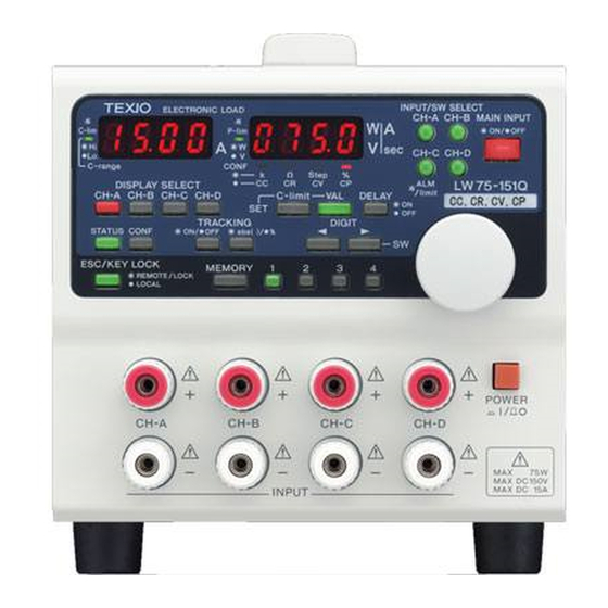
Page 20: Panels
4. PANELS 4-1 Front Panel 1. Model name ・One of the following model names is marked in this position. LW75-151Q (75 W, 150 V, 15 A, four inputs), LW151-151D (150 W, 150 V, 30 A, two inputs), LW301-151S (300 W, 150 V, 30 A or 60 A, one input), and LW75-151D (75 W, 150 V, 15 A, two inputs) LW75-151Q 2. - Page 21 5. C-range indicator LED (lit in green) C-lim indicator LED (blinking in green) Current range indication function ・Stays on when the channel of the DISCHARGE SELECT key lit in orange is in the H current range. Stays off when it is in the Low current range. Current limitation status indication function ・Blinks when the channel of the DISCHARGE SELECT key lit in orange is in the current limitation status.
- Page 22 10. DISPLAY SELECT key (lit in orange, green or red) Display channel selection function ・The key of the channel displayed on the A display and V/W display units is lit Tracking setting status display function ・Displays the tracking setting. NOTE: The LW301-151S does not have this function. Alarm releasing function ・Releases the alarm status.
- Page 23 19. ESC/KEY LOCK key (lit in green) Escape function (Switching over from setting condition to non-setting condition) ・Changes the setting condition into the input value display condition. Key locking function ・The keys are locked when this key is lit. NOTE: This unit switches over from the setting condition to non-setting condition before it enters the key lock status.
-
Page 24: Rear Panel
4-2 Rear Panel 27. Optional board mount ・Mount the optional board IF-50GP or IF-50USB in this position. ・A dummy panel is mounted in this position of a model with no optional board. (The interface board is installed by option when the user places an order.) ・A model with the external voltage control function (factory option) has the external voltage control terminals. - Page 25 30. Rear input terminals and voltage remote sensing terminals ・The rear input terminals and voltage remote sensing terminals of the unit. Observe the current, voltage and power ranges marked on the panel. ・The input terminals on the rear panel are connected with the terminals on the front panel. Voltage supplied by the power source is applied to these terminals even in the condition where the terminals on the front panel are used and these terminals are not used.
-
Page 26: Optional Board Mount
4-3 Optional Board Mount The optional board mount is located at the top of the rear panel with the optional board mount cover removed. NOTE: 1) Stop the electric power supply from the source of on electric power supply before this operation. -
Page 27: Before Using Unit
5. BEFORE USING UNIT 5-1 Position of Voltage Remote Sensing Selector Switches Be sure to disconnect the AC power cable from the unit before using these switches. Cut off electric power from the power supply to the unit as well. ・Detach the optional board mount cover. -
Page 28: Connection Of Power Supply
5-2 Connection of Power Supply ・Connect the power supply with the input terminal of the unit firmly using crimp-style terminals, etc. ・Connect load wires that sufficiently bear the current capacity between the LW unit and power source. ・For safety, be sure to confirm that the MAIN INPUT key of the unit is off before connecting or disconnecting the cable. -
Page 29: Connecting With Input Terminals On Rear Panel
5-2-2 Connecting with input terminals on rear panel NOTE: The input terminals on the rear panel have bare metallic parts. Be sure to keep the supplied rear terminal cover on them. 1. Turn off the MAIN INPUT key of the unit. 2. -
Page 30: Turning On Power
5-3 Turning On Power 5-3-1 Display when turning on power ・Connect the AC power cable supplied with the unit properly, and throw the power switch. Until the unit enters the normal operating condition, the numbers and characters shown in 1 to 5 below are displayed on the A and V/W display units. -
Page 31: Setting When Turning On Power And Storing Setting
5-3-2 Setting when turning on power and storing setting ・The table below shows the default setting and the setting after initializing the memory. Item Initial setting Savable or not INPUT SELECT key All ON ○ SW SELECT key All OFF ○... -
Page 32: Alarm
5-4 Alarm 5-4-1 EAR (External alarm) This alarm occurs when pins 1 and 2 of the external contact control connector (J1) on the rear panel are short-circuited. The following shows the indication of the unit when this alarm occurs. INPUT/SW SELECT MAIN INPUT Crang ●Hi... -
Page 33: Limit Functions
5-5 Limit Functions 5-5-1 Over-power limit (OPL) This function works when the input power of the unit exceeds 115% of the rated power. The following shows the indication in this limit status. NOTE: If operation continues in this status, an OHA may occur. INPUT/SW SELECT MAIN INPUT Crang... -
Page 34: Functions And Operation Procedures
6. FUNCTIONS AND OPERATION PROCEDURES 6-1 Operation Method Selecting Function This unit provides three selectable operation methods shown below. 1. Switching method selection: It is possible to select two switching time setting methods: Frequency and duty, and Ta time and Tb time. -
Page 35: Switching Method Selection
6-1-2 Switching method selection STATUS key STATUS key ESC/KEY LOCK key MEMORY Key Switching method A display unit: "cond" V/W display selection display V/W display unit: "1" unit: "F-du" A display unit: "Su" Saving switching ESC/KEY LOCK setting method Rotary encoder V/W display Normal display operation... -
Page 36: Rear Contact Function Selection
6-1-4 Rear contact function selection STATUS key STATUS key ESC/KEY LOCK key MEMORY key Rear contact function A display unit: "cond" V/W display selection display unit: "PrE" V/W display unit: "3" A display unit: "ESEL" Saving rear contact function ESC/KEY LOCK key V/W display Rotary encoder Normal display... -
Page 37: Function Setting Mode
6-2 Function Setting Mode This unit is capable of setting the following four parameters individually. 1. Delay time The delay time of each channel may be set. However, the LW301-151S does not have this function. 2. Tracking operation The tracking operation of each channel may be set. However, the LW301-151S does not have this function. -
Page 38: Delay Time Setting
6-2-2 Delay time setting Set the time of turning on or off the input of each channel by turning on or off the main input. DISPLAY SELECT key MEMORY key Saving delay Delay time setting Increasing/de A display unit: time in creasing or screen EEPROM... -
Page 39: Tracking Operation Setting
6-2-3 Tracking operation setting Select whether to execute tracking of each channel. MEMORY key DISPLAY SELECT key Saving tracking Tracking setting Setting & changing tracking of each operation setting screen channel in EEPROM. DISPLAY SELECT key On/Off A display unit: "trAc" condition V/W display unit: "----"... -
Page 40: Discharge Mode Setting
6-2-4 Discharge mode setting One-time operation sets the discharge mode of one PRESET, though it sets the discharge modes of all channels. Thus, in discharge mode setting, turn on the PRESET key whose discharge mode should be set before pressing the STATUS key. DISPLAY SELECT key MEMORY key Changes... -
Page 41: Switching Time Setting Method 1
6-2-5 Switching time setting method 1 Set the duty and frequency in switching. This operation is disabled unless the "frequency and duty" switching time setting method is selected. Rotary encoder DIGIT key + rotary encoder operation STATUS key STATUS key operation MEMORY key Changing... -
Page 42: Switching Time Setting Method 2
6-2-6 Switching time setting method 2 Set the Ta time and Tb time in switching. This operation is disabled unless the " Ta time and Tb time" switching time setting method is selected. Rotary encoder DIGIT key + rotary encoder operation STATUS key STATUS key operation... -
Page 43: Changing Input Voltage Display And Input Power Display
6-2-7 Changing input voltage display and input power display INPUT/SW SELECT MAIN INPUT Crang ●Hi ●W ○Low ○V Ω Step % ON●/OFF○ cc cr cv cp DISPLAY SELECT Input voltage or input power is displayed. STAT CONF OFF: Voltage, ON: Power Input current is displayed. -
Page 44: Display Of Two Input Current Values: The Lw301-151S Does Not Have This Function
6-2-9 Display of two input current values: The LW301-151S does not have this function. INPUT/SW SELECT MAIN INPUT Crang ●Hi ●W ○Low ○V Ω Step % ON●/OFF○ cc cr cv cp DISPLAY SELECT Input current of right DISPLAY SELECT Clim DELAY ●ON key lit in orange is displayed. - Page 45 2. When the VAL key is lit, the digits of the A and V/W display units blink. However, when the lowest digit of the set value is to be increased or decreased in the condition where the CONF key is off, that digit does not blink. The blinking digits in each display condition are as shown below.
-
Page 46: Increasing And Decreasing Set Values Of Cr Mode
6-2-11 Increasing and decreasing set values of CR mode Select an intended digit of the STEP value (five digits from the highest digit in all) of the CR mode with the DIGIT key and increase or decrease it with the rotary encoder. The digit to be increased or decreased is indicated by a blinking digit of the A or V/W display unit in the condition where the VAL key is lit. - Page 47 3. When the DIGIT key is operated in the condition in step 2, the blinking digit of the A or V/W display unit moves to the right or left. Pressing the left DIGIT key moves the blinking digit to the left. Pressing the right DIGIT key moves the blinking digit to the left. STEP value display and input value display If the leftmost digit is blinking, it does not change even if the left DIGIT key is pressed.
-
Page 48: Setting Cr Mode Value By Means Of Voltage And Current Setting
6-2-12 Setting CR mode value by means of voltage and current setting It is possible to set the CR mode value by setting the voltage and current. 1. Bring the unit into the constant-resistance mode. Turn off the TRACKING ON/OFF, CONF, VAL and C-lim keys and display the applied voltage on the V/W display unit. -
Page 49: Increasing And Decreasing Current Limit Set Value
5. When the DISPLAY SELECT key lit in orange is pressed after increasing or decreasing the voltage displayed on the V/W display unit and current displayed on the A display unit in steps 3 and 4, the VAL key goes out, the C-lim key goes out, and the CR mode resistance is set as shown below. -
Page 50: Memory Functions
3. When the DIGIT key is operated in the condition in step 2, the blinking digit of the A or V/W display unit moves to the right or left. Pressing the left DIGIT key moves the blinking digit to the left, and pressing the right DIGIT key moves the blinking digit to the left. If the leftmost digit is blinking, it does not change even if the left DIGIT key is pressed. -
Page 51: Recalling Preset Data With Preset Keys
6-3-3 Recalling preset data with PRESET keys 1. Set the discharge modes and set values with two or more PRESET keys, and press those PRESET keys to turn on the keys in green. Turn off the CONF key in the condition where the MAIN INPUT key is lit (input values are displayed on the A and V/W display units). -
Page 52: Initializing Set Value
3. When the VAL key is pressed in step 2, it is lit. The first digits of the set values displayed on the A and V/W display units blink. In this condition, it is possible to move the blinking digits with the DIGIT key and increase or decrease the set value with the rotary encoder INPUT/SW SELECT MAIN INPUT... -
Page 53: Input Functions
6-4 Input Functions This is a multi-input type electronic loading unit, which is capable of turn on or off the input of each channel independently. The input of each channel is turned on or off with the INPUT/SW SELECT keys. The inputs of all channels are turned on or off with the MAIN INPUT key. To turn on the inputs of this unit, make both the INPUT/SW SELECT and MAIN INPUT keys lit. -
Page 54: Switching Functions
6-5 Switching Functions ・This is a multi-input type electronic loading unit capable of turning on or off switching of each channel. Turn on or off switching of each channel with the INPUT/SW SELECT keys. ・This unit switches the set values of the discharge modes set to PRESET 1 and 2 (PRESET key 1 or 2 is selected) or PRESET 3 and 4 (PRESET key 3 or 4 is selected) at a certain interval. -
Page 55: Delay Functions
6-6 Delay Functions ・It is possible to delay the point of turning on (or off) the input of each channel by 0.1 to 10.0 seconds from the moment when operating the MAIN INPUT key. ・During the delay function is working (MAIN INPUT key is blinking), no operations are enabled, except for the MAIN INPUT key. -
Page 56: Tracking Functions
6-7 Tracking Functions ・The tracking function increases or decreases the set values of several channels simultaneously. Two tracking modes are available: "Absolute value tracking mode" that increases or decreases the set values of the channels by the same value, and "% tracking mode" that increases or decreases the set values by percentage, assuming the value when tracking is turned on as 100%. -
Page 57: Increasing Or Decreasing Set Value In Absolute Value Tracking Mode
NOTE: 1) If tracking is not set in any channels, it is impossible to turn on the TRACKING ON/OFF key. 2) It is impossible to activate tracking while the DISPLAY SELECT key of the channel in which tracking is not set is lit in orange. 3) When the DISPLAY SELECT key of the channel in which tracking is not set is lit in orange, the DISPLAY SELECT key of all channels in which tracking is set go out. -
Page 58: Increasing Or Decreasing Set Value In % Tracking Mode
6-7-4 Increasing or decreasing set value in % tracking mode 1. Turn on the DISPLAY SELECT key of the channel in which tracking is set and TRACKING abs ()/% key. Turn off the VAL key. 2. Turn on the TRACKING ON/OFF key. In the % tracking mode, the set value of each channel is regarded as 100% when this key goes on. -
Page 59: Checking Set Value In % Tracking Mode
6-7-5 Checking set value in % tracking mode 1. Bring the unit into the absolute value tracking mode. Turn on the CONF key. The set % values are displayed on the A and V/W display units. 2. Press the DISPLAY SELECT key lit in orange. It blinks in orange, and the set values are displayed on the A and V/W display units. -
Page 60: Example Of Increasing/Decreasing Set Values With Tracking Mode Active
6-7-6 Example of increasing/decreasing set values with tracking mode active The table below shows an example of increasing or decreasing the set values of the LW75-151Q when the tracking mode is activated. Set current with tracking mode active Tracking setting Channel A 5.00 A +... -
Page 61: Occurrence Of Oha (Overheat Alarm) And Releasing It
6-8-2 Occurrence of OHA (overheat alarm) and releasing it 1. If this alarm occurs, the MAIN INPUT key goes out and the inputs of all channels are turned off forcedly. 2. When the unit is in the OHA status, "AL Π" and "oHA" are displayed on the A and V/W display units, respectively. -
Page 62: Key Lock Function
6-9 Key Lock Function ・This function alternates the key locked status and local status of the unit. ・Key locked status (lit in green): Any keys, except for the ESC/KEY LOCK key, are not functional. ・Local status (lit in red): The unit is in the remote control mode. Any keys, except for the ESC/KEY LOCK key, are not functional. -
Page 63: External Contact Control
7. EXTERNAL CONTACT CONTROL 7-1 Functions ・It is possible to operate the MAIN INPUT key and PRESET keys 1 to 4 or INPUT SELECT key of the unit using, input and output of alarm signal through the external contact input and output connector (J1) on the rear panel. -
Page 64: Usage
・Use the lead wires with a connector supplied with the unit for the connector J1. The lead wires with a connector are color-coded according to the marks on J1 on the rear panel. ・If it is necessary to extend the lead wires with a connector supplied with the unit, solder them properly and wind insulation tube around the connections to protect them. -
Page 65: Turning On/Off Input Select Using External Contacts
7-3-3 Turning ON/OFF input select using external contacts 1. Open J1 pin 3 and pin 4 to 7 of the unit. All INPUT SELECT keys go out (Off). 2. Short-circuit J1 pin 3 and one of pins 4 to 7 of the unit. The INPUT SELECT key of the channel A is lit (ON) in green when pin 4 is short-circuited. -
Page 66: External Voltage Control
8. EXTERNAL VOLTAGE CONTROL ・This function is only available on the models, which are provided with the external voltage control function. This function is a factory option. ・It is possible to set the value of each discharge mode of the unit by applying external voltage (0 to 10 V) to the external voltage input connector (hereinafter referred to as J2) on the rear panel. -
Page 67: Specifications Of Controls
8-1-3 Specifications of controls Function Control name LW75-151Q LW75-151D LW151-151D LW301-151S OFFSET 1 Adjusting channel A offset GAIN 1 Adjusting channel A gain OFFSET 2 Adjusting channel B offset Unused GAIN 2 Adjusting channel B gain Adjusting channel Adjusting channel OFFSET 3 C offset B offset... -
Page 68: Adjusting Set Value Using External Voltage
8-2-2 Adjusting set value using external voltage 1. Turn off the main input. Cause the DISPLAY SELECT key of the external-voltage-control channel to be lit in orange. 2. Turn off the VAL key and C-lim key, and turn on the CONF key. The value set by the external voltage control function is displayed on the A and V/ W display units. -
Page 69: Operation In Cc Mode
8-2-3 Operation in CC mode The set value in the CC mode is the sum of the set value increased or decreased on the panel and the value set by the external voltage control function. Set 0 A on the panel when using the value set by the external voltage control function only. -
Page 70: Relationship Between External Voltage And Set Value In Cc Mode
8-2-4 Relationship between external voltage and set value in CC mode Voltage [V] External voltage Rated value [%] Value set by external voltage control function is displayed. Rated value [%] Set value increased or decreased on panel is displayed. Rated value [%] Set value of this unit (On-panel setting + external voltage) Description... -
Page 71: Operation In Cr/Cv/Cp Mode
8-2-5 Operation in CR/CV/CP mode The value set by the external voltage control function serves as the set value in any other modes than the CC mode. It is impossible to increase or decrease the set value on the panel in any mode than the CC mode. -
Page 72: Remote Control
・It is necessary to set the PC address and system address of the local bus master when controlling the LW units through the GP-IB or USB. Set the system address to the slave unit. ・The LW series may only be connected. 9-1-1 Control through GP-IB ・It is possible to connect a maximum of 14 local bus masters directly with a computer using GP-IB... -
Page 73: Connection Figure Of If-50Gp/Usb
9-1-3 Connection Figure of IF-50GP/USB Twisted pair cables GP-IB: Control computer + GP-IB board USB: USB-c omp atible c ontrol c omput er Local bus master 1, GP-IB: GP-IB Slave 1: Slave 2: Slave LW+IF-50xx (GP-IB: cable LW+IF-50GP/USB LW+IF-50GP/USB 31:LW+IF-50GP/USB …... -
Page 74: Connection Of If-50Gp/1F-50Usb Local Bus
9-1-4 Connection of IF-50GP/1F-50USB local bus Observe the following instructions and connect the local bus with twisted pair cables. ・The total length of the bus must be 200 meters or less. Its resistance must be 50 ?. ・Turn on both switches S1 of the local bus masters and the IF-50GP/1F-50USB connected at the end of the bus only. -
Page 75: Address Setting
LF + null packet, CR, LF + null packet, null packet only ・If the USB driver is needed, you may download it from the homepage shown below. Contact our agent if it is impossible to download it. http://www.texio.co.jp You may also download API and sample programs. -
Page 76: Precautions For Sending Commands
9-4 Precautions for Sending Commands 9-4-1 Sending commands ・It is possible to write several commands on a single line by separating them with the separators ";" when sending them through the GP-IB or USB. The maximum of 80 characters may be written on a single line. -
Page 77: Commands
10. COMMANDS 10-1 Setting Commands 10-1-1 Setting units to be controlled Command name : SV Function : Sets a system address of an electronic load to be controlled. Command format : SV□ sa (, sa , ..., sa ) sa : 0, 1 to 32 This command sets a system address of an electronic load to be controlled. -
Page 78: Main Input On/Off
1: Selects the CC mode and H current range. 2: Selects the CC mode and L current range. 3: Selects the CR mode and H current range. 4: Selects the CR mode and L current range. 5: Selects the CV mode and H current range. 6: Selects the CV mode and L current range. -
Page 79: Setting Discharge Mode Set Value
10-1-6 Setting discharge mode set value Command name : VALUE Function : Sets a set value in each discharge mode. Command format : VALUE□ pre , ch , data pre : PRESET key 1: PRESET 1 key, 2 : PRESET 2 key, 3: PRESET 3 key, 4: PRESET 4 key ch : Channel 1: Channel A, 2: Channel B, 3: Channel C, 4: Channel D data : Set data... -
Page 80: Setting Current Limit Value
10-1-8 Setting current limit value Command name : CLIM Function : Sets the current limit value. Command format : CLIM□ pre , ch , data pre : PRESET key 1: PRESET 1 key, 2 : PRESET 2 key, 3: PRESET 3 key, 4: PRESET 4 key ch : Channel 1: Channel A, 2: Channel B, 3: Channel C, 4: Channel D data : Current limit value... -
Page 81: Setting Switching Frequency
10-1-11 Setting switching frequency Command name : SWFREQ Function : Sets the switching frequency. Command format : SWFREQ□ data data : Switching frequency Integer data (1 to 500) in units of Hz. A maximum of three characters. NOTE: 1) This command is not executed if the switching method is "Ta time and Tb time". 2) This command does not save the set data in the EEPROM. -
Page 82: Changing Switching Method
10-1-14 Changing switching method Command name : SWSET Function : Changes the switching setting method Command format : SWSET□ flg flg : Switching method 0: frequency and duty, 1: Ta time and Tb time NOTE: 1) The switching parameter is set again in accordance with the specified setting method after completion of setting. -
Page 83: Saving Discharge Mode Set Value In Eeprom
10-1-18 Saving discharge mode set value in EEPROM Command name : VALWRT Function : Saves the discharge mode set value in the EEPROM. Command format : VALWRT□ pre , ch pre : PRESET key 1: PRESET 1 key, 2 : PRESET 2 key, 3: PRESET 3 key, 4: PRESET 4 key ch : Channel 1: Channel A, 2: Channel B, 3: Channel C, 4: Channel D Example: VALWRT 1,1 ... -
Page 84: Selecting Input Value Display Channel
10-1-22 Selecting input value display channel Command name : DISPSEL Function : Selects a channel whose input value is to be displayed on the V/W and A display units. Command format : DISPSEL□ ch ch : Channel 1: Channel A, 2: Channel B, 3: Channel C, 4: Channel D NOTE: 1) In the remote mode, the input value is always displayed on the V/W and A display units. -
Page 85: Tracking Setting
10-1-26 Tracking setting Command name : TRSET Function : Sets tracking in each channel. Command format : TRSET□ seta , setb , setc , setd seta : Sets tracking of channel A. 0: No tracking, 1: + tracking, 2: - tracking setb : Sets tracking of channel B. -
Page 86: Increasing/Decreasing Set Value In Tracking Operation
10-1-29 Increasing/decreasing set value in tracking operation Command name : TRVAL Function : Increases or decreases the set value in tracking operation. Command format : TRVAL□ data data : Amount of increase/decrease Input an increase/decrease amount in a real number in the absolute value tracking mode. -
Page 87: Query Commands
Example: * IDN? ... Inquires about the ID of the option board built in the local bus master and the model ID of this unit. * IDN TEXIO, IF-50GP, 0, 1.00 ... The mounted option board is the IF-50GP. The ROM version of the IF-50GP is 1.00. -
Page 88: Query About Input Value
10-2-4 Query about input value Command name : MONDATA? Function : Inquires about an input value. ◇Query Command format : MONDATA? □ ch ch : Channel 1: Channel A, 2: Channel B, 3: Channel C, 4: Channel D ◇Response Command format : MONDATA□ sys , cur , volt , watt sys : System address 1 to 32 cur : Input current Real number data in units of A. -
Page 89: Query About Main Input On/Off Status
◇Response Command format : LMODE□ sys , mode sys : System address 1 to 32 mode : Discharge mode of the specified channel 1: CC mode, H current range. 2: CC mode, L current range. 3: CR mode, H current range. 4: CR mode, L current range. -
Page 90: Query About Input Select Status
10-2-8 Query about input select status Command name : INPSEL? Function : Inquires about the input select status. ◇Query Command format : INPSEL? □ ch ch : Channel 1: Channel A, 2: Channel B, 3: Channel C, 4: Channel D ◇Response Command format : INPSEL□... -
Page 91: Query About Set Current Limit
◇Response Command format : SVALUE□ sys , data sys : System address 1 to 32 data : STEP value in CR mode Integer data between 3 and 30000. A maximum of five characters. NOTE: This command is not executed unless the specified channel is in the CR mode. Example: SVALUE? 1,1 ... -
Page 92: Query About Switching Frequency
10-2-13 Query about switching frequency Command name : SWFREQ? Function : Inquires about the switching frequency. ◇Query Command format : SWFREQ? ◇Response Command format : SWFREQ□ sys , data sys : System address 1 to 32 data : Set switching frequency Integer data. -
Page 93: Query About Switching Method
10-2-16 Query about switching method Command name : SWSET? Function : Inquires about the switching method. ◇Query Command format : SWSET? ◇Response Command format : SWSET□ sys , flg sys : System address 1 to 32 flg : Switching setting method 0: Frequency and duty, 1: Ta time and Tb time Example: SWSET? ...Inquires about the switching method. -
Page 94: Query About Unit Id Number
10-2-19 Query about unit ID number Command name : ID? Function : Inquires about the unit ID number. ◇Query Command format : ID? ◇Response Command format : ID□ sys , id sys : System address 1 to 32 id : Model ID number Integer data. -
Page 95: Query About Alarm Status
10-2-21 Query about alarm status Command name : ALARM? Function : Inquires about the alarm status. ◇Query Command format : ALARM? ◇Response Command format : ALARM□ sys , eta , oha , ova , oca , 0000 sys : System address 1 to 32 eta : EAR status 0: Normal, 1: alarm oha : OHA status... -
Page 96: Query About Input Value Display Channel
10-2-23 Query about input value display channel Command name : DISPSEL? Function : Inquires about the channel whose input is displayed. ◇Query Command format : DISPSEL? ◇Response Command format : DISPSEL□ sys , ch sys : System address 1 to 32 ch : Channel 1: Channel A, 2: Channel B, 3: Channel C, 4: Channel D Example: DISPSEL? ... -
Page 97: Query About Tracking Setting
10-2-26 Query about tracking setting Command name : TRSET? Function : Inquires about tracking setting in each channel. ◇Query Command format : TRSET? ◇Response Command format : TRSET□ sys , seta , setb , setc , setd sys : System address 1 to 32 seta : Tracking setting of channel A 0: No tracking is set, 1: + tracking is set, 2: - tracking is set. -
Page 98: Query About % Tracking Mode Set Value
10-2-29 Query about % tracking mode set value Command name : TRVAL? Function : Inquires about the set value in the % tracking mode. ◇Query Command format : TRVAL? ◇Response Command format : TRVAL□ sys , data sys : System address 1 to 32 data : % tracking set value Real number data (0.0 to 200.0). -
Page 99: Command List
10-3 Command List 10-3-1 Setting commands Item Command Page SV system address, ..., system address Setting units to be controlled PRESET preset number PRESET key selection LMODE preset specification, channel, discharge mode, Discharge mode setting external control setting Main input ON/OFF MINPUT ON/OFF INPSEL channel, ON/OFF setting Input select ON/OFF... -
Page 100: Query Commands
10-3-2 Query comman ds Item Command Response Page Sending system address of SV query command response address, SV? controlled units controlled units' addresses Sending addresses of all SLV? SLV all units' system addresses slave units Sending option board ID & *IDN company name, option board *IDN?... -
Page 101: Trouble-Looking Phenomena
11. TROUBLE-LOOKING PHENOMENA Check the matters shown below if the unit operation condition becomes abnormal. Phenomenon Possible cause Countermeasure AC cable is not connected Conn ect th e AC c ab le p rop erly. properly or broken. Rep lace it if b roke n. Power is not turned on Input AC voltage is too high, even if power switch is... -
Page 102: Outside Dimensions
12. OUTSIDE DIMENSIONS 3.35 15.5... - Page 104 7F Towa Fudosan Shin Yokohama Bldg. 2-18-13, Shin Yokohama, Kohoku-ku,Yokohama, Kanagawa, 222-0033 Japan http://www.texio.co.jp/...
Need help?
Do you have a question about the LW Series and is the answer not in the manual?
Questions and answers