Huawei RRU User Manual
Hide thumbs
Also See for RRU:
- Hardware maintenance manual (58 pages) ,
- Installation manual (103 pages)

Related Manuals for Huawei RRU


Summary of Contents for Huawei RRU
- Page 1 V200R001 User Guide Issue Date 2008-04-18 Part Number 00394301 Huawei Proprietary and Confidential Copyright © Huawei Technologies Co., Ltd...
- Page 2 Huawei Technologies Co., Ltd. provides customers with comprehensive technical support and service. For any assistance, please contact our local office or company headquarters. Huawei Technologies Co., Ltd. Address: Huawei Industrial Base Bantian, Longgang Shenzhen 518129 People's Republic of China Website: http://www.huawei.com...
-
Page 3: Table Of Contents
2.3.1 PGND cable of the RRU........................2-11 2.3.2 Power Cable of the RRU........................2-11 2.3.3 CPRI Optical Cable..........................2-12 2.3.4 AISG Multi-Wire Cable of the RRU/SRXU..................2-13 2.3.5 AISG Extension Cable of the RRU/SRXU..................2-14 2.3.6 RF Jumper of the RRU/SRXU......................2-15 2.3.7 Alarm Cable of the RRU........................2-18 2.4 SRXU Cables..............................2-19... - Page 4 3.7.6 Installing the AISG Multi-Wire Cable of the RRU/SRXU..............3-113 3.7.7 Installing the AISG Extension Cable of the RRU/SRXU..............3-114 3.7.8 Opening and Closing the Cover Plate of the RRU Cabling Cavity...........3-114 3.7.9 Opening and Closing the Cover Plate of the SRXU Cabling Cavity..........3-114 3.8 Powering On the RRU/SRXU........................3-114...
- Page 5 User Guide Contents 4.2.1 Powering On the RRU/SRXU........................4-2 4.2.2 Powering Off the RRU/SRXU.......................4-4 4.3 Replacing an RRU............................4-4 4.4 Replacing an SRXU............................4-6 4.5 Replacing an Optical Module..........................4-8 Index..............................i-1 Issue 01 (2008-04-18) Huawei Proprietary and Confidential Copyright © Huawei Technologies Co., Ltd...
- Page 7 Figure 3-6 Installation modes of three RRUs and three SRXUs................3-7 Figure 3-7 Recommended space requirements of one RRU with and without the SRXU (unit: mm)....3-8 Figure 3-8 Minimal space requirements of one RRU with and without the SRXU (unit: mm)......3-9...
- Page 8 Figure 3-40 Drilling a hole and installing the expansion bolt assembly............3-37 Figure 3-41 Securing the mounting plate......................3-38 Figure 3-42 Filling tube, insulating washer, and insulating block..............3-38 Figure 3-43 One RRU in ordinary mode and the other in reverse mode............3-39 Figure 3-44 Securing the attachment plate......................3-40 Figure 3-45 Installing the module........................3-41 Figure 3-46 Securing the module........................3-42...
- Page 9 Figure 3-88 Installing the second module......................3-72 Figure 3-89 Securing the second module......................3-73 Figure 3-90 Installing the third module......................3-74 Figure 3-91 Securing the third module.......................3-75 Figure 3-92 Holes in the multi-purpose attachment plate..................3-76 Issue 01 (2008-04-18) Huawei Proprietary and Confidential Copyright © Huawei Technologies Co., Ltd...
- Page 10 Figure 3-110 SRXUs installed on the two RRUs....................3-88 Figure 3-111 Remove the plastic housings......................3-89 Figure 3-112 Securing the connecting boards to the RRU module that is in ordinary mode......3-90 Figure 3-113 Securing the attachment plate to one SRXU................3-90 Figure 3-114 Installing the SRXU........................3-91 Figure 3-115 Securing the SRXU........................3-92...
- Page 11 Figure 3-135 Twisting the shielding layer into one strand................3-105 Figure 3-136 Power cable with the heat-shrinkable tube.................3-105 Figure 3-137 Waterproofed joints........................3-107 Figure 3-138 CPRI_W port in the RRU cabling cavity...................3-109 Figure 3-139 Strap and waterproof filler......................3-110 Figure 3-140 CPRI_W port in the SRXU cabling cavity.................3-111 Figure 3-141 Cable trough for the optical cable in the SRXU cabling cavity..........3-112...
- Page 13 Tables Tables Table 2-1 LEDs on the RRU..........................2-3 Table 2-2 Ports and LEDs on the panels of the RRU...................2-6 Table 2-3 LEDs on the SRXU..........................2-7 Table 2-4 Ports and LEDs on the panels of the SRXU..................2-10 Table 2-5 Pin assignment for the wires of the –48 V DC power cable (North American Standard)....2-12 Table 2-6 Pin assignment for the wires of the –48 V DC power cable (European Standard)......2-12...
-
Page 15: About This Document
User Guide About This Document About This Document Purpose This document describes the RRU hardware and provides instructions in hardware installation, cable connections, hardware installation check, and hardware maintenance. This document is applicable to RRU3804 and RRU3801E. Product Versions The following table lists the product versions related to this document. - Page 16 This describes how to install the hardware, route the cables, and check the hardware installation of the RRU and SRXU. 4 Maintaining RRU and SRXU Hardware After the RRU and SRXU are deployed, accepted, and put into use, routine maintenance is performed to ensure the functionality of the modules. Conventions 1.
- Page 17 Press the primary mouse button twice continuously and quickly without moving the pointer. Drag Press and hold the primary mouse button and move the pointer to a certain position. Issue 01 (2008-04-18) Huawei Proprietary and Confidential Copyright © Huawei Technologies Co., Ltd...
-
Page 19: Safety Information
This symbol indicates that serious or major injury may occur if you ignore the safety instruction. NOTE This symbol indicates that the operation may be easier if you pay attention to the safety instruction. Issue 01 (2008-04-18) Huawei Proprietary and Confidential Copyright © Huawei Technologies Co., Ltd... - Page 20 Any replacement of the device or part of the device (including the software) or any change made to the device must be performed by qualified or authorized personnel of Huawei. Any fault or error that might cause safety problems must be reported immediately to the personnel in charge.
-
Page 21: Electricity Safety
In a thunderstorm, do not perform operations on high voltage and AC power supply facilities or on a steel tower and mast. High Electrical Leakage CAUTION Ground the device before powering on the device. Otherwise, the personnel and device are in danger. Issue 01 (2008-04-18) Huawei Proprietary and Confidential Copyright © Huawei Technologies Co., Ltd... - Page 22 (ASICs), wear a grounded ESD wrist strap. It can prevent the sensitive components from being damaged by the static electricity in the human body. Figure 1-1shows how to wear an ESD wrist strap. Huawei Proprietary and Confidential Issue 01 (2008-04-18) Copyright © Huawei Technologies Co., Ltd...
-
Page 23: Inflammable Environment
Electrolyte overflow may damage the device. It will corrode the metal parts and the circuit boards, and ultimately damage the device and cause short-circuit of the circuit boards. Issue 01 (2008-04-18) Huawei Proprietary and Confidential Copyright © Huawei Technologies Co., Ltd... - Page 24 High temperature may result in distortion, damage, and electrolyte overflow of the battery. When the temperature of the battery exceeds 60 C, check whether there is acid overflow. If acid overflow occurs, handle the acid immediately. Huawei Proprietary and Confidential Issue 01 (2008-04-18) Copyright © Huawei Technologies Co., Ltd...
-
Page 25: Radiation
BTSs. The antenna should be located in an area that is inaccessible to the public where the RF radiation exceeds the stipulated value. Issue 01 (2008-04-18) Huawei Proprietary and Confidential Copyright © Huawei Technologies Co., Ltd... - Page 26 Before cutting or splicing an optical fiber, ensure that the optical fiber is disconnected from the optical source. After disconnecting the optical fiber, use protecting caps to protect all the optical connectors. Huawei Proprietary and Confidential Issue 01 (2008-04-18) Copyright © Huawei Technologies Co., Ltd...
-
Page 27: Working At Heights
Use a concise instruction to prevent incorrect operation. The angle between the two cables should be less than or equal to 90 in the lifting of weights (See Figure 1-2). Issue 01 (2008-04-18) Huawei Proprietary and Confidential Copyright © Huawei Technologies Co., Ltd... -
Page 28: Figure 1-2 Lifting A Weight
If you tend to climb to the roof, the length of the ladder should be at least one meter higher than the eave, as shown in Figure 1-4. 1-10 Huawei Proprietary and Confidential Issue 01 (2008-04-18) Copyright © Huawei Technologies Co., Ltd... -
Page 29: Mechanical Safety
Before drilling a hole on the cabinet, remove the cables from the cabinet. During the drilling, wear blinkers to protect your eyes. Issue 01 (2008-04-18) Huawei Proprietary and Confidential 1-11 Copyright © Huawei Technologies Co., Ltd... -
Page 30: Others
Inserting and Removing a Board CAUTION When inserting a board, wear the ESD wrist strap or gloves. Insert the board gently to prevent any bent pins on the backplane. 1-12 Huawei Proprietary and Confidential Issue 01 (2008-04-18) Copyright © Huawei Technologies Co., Ltd... - Page 31 24 hours before installation. Move the cables with care, especially at a low temperature. Do not drop the cables directly from the vehicle. Issue 01 (2008-04-18) Huawei Proprietary and Confidential 1-13 Copyright © Huawei Technologies Co., Ltd...
-
Page 33: Rru And Srxu Hardware
The SRXU is an extended RF interface module that provides two RX channels for RF signals. 2.3 RRU Cables The RRU cables include the PGND cable, power cable, AISG multi-wire cable, AISG extension cable, CPRI optical cable, RF jumper, and alarm cable. -
Page 34: Rru Equipment
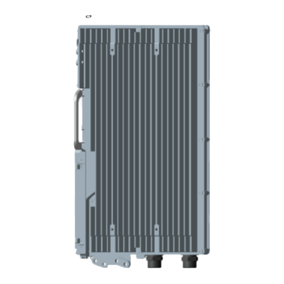
RRU. On the left is a front view of the RRU without the housing, in the middle is a side view of the RRU without the housing, and on the right is a front view of the RRU housing. -
Page 35: Leds On The Rru
2 RRU and SRXU Hardware 2.1.2 LEDs on the RRU The LEDs, on the LED panel of the RRU, indicate the running status of the RRU. For the positions of the LEDs on the RRU, refer to 2.1.3 Panels of the RRU. -
Page 36: Panels Of The Rru
The optical module is not in position or is powered off. 2.1.3 Panels of the RRU The RRU has a bottom panel, a cabling cavity panel, and an LED panel. Figure 2-2 shows the panels of the RRU. Huawei Proprietary and Confidential Issue 01 (2008-04-18) Copyright ©... -
Page 37: Figure 2-2 Panels Of The Rru
User Guide 2 RRU and SRXU Hardware Figure 2-2 Panels of the RRU Table 2-2 describes the ports and LEDs on the panels of the SRXU. Issue 01 (2008-04-18) Huawei Proprietary and Confidential Copyright © Huawei Technologies Co., Ltd... -
Page 38: Srxu Equipment
The SRXU receives RF signals from the antenna system, down-converts the RF signals to IF signals, and then transmits them to the RRU after amplification, analog-to-digital conversion, digital down-conversion, matched filtering, and DAGC. The RRU forwards the signals to the BBU or the macro NodeB. -
Page 39: Appearance Of The Srxu
User Guide 2 RRU and SRXU Hardware 2.2.1 Appearance of the SRXU The SRXU features a modular structure with its ports at the module bottom and on the cabling cavity. Figure 2-3 shows the SRXU. On the left is a front view of the SRXU, and on the right is a side view of the SRXU. -
Page 40: Panels Of The Srxu
2 RRU and SRXU Hardware User Guide Label Color Status Description The optical module is not in position or is powered off. CPRI_E Red/green ON (green) The CPRI link is normal. ON (red) The optical module receives local alarms related to LOS. -
Page 41: Figure 2-4 Panels Of The Srxu
User Guide 2 RRU and SRXU Hardware Figure 2-4 Panels of the SRXU Table 2-4 describes the ports and LEDs on the panels of the SRXU. Issue 01 (2008-04-18) Huawei Proprietary and Confidential Copyright © Huawei Technologies Co., Ltd... -
Page 42: Rru Cables
The PGND cable ensures the grounding of the RRU. 2.3.2 Power Cable of the RRU The RRU uses a shielded -48 V DC power cable. The cable feeds external -48 V DC power to the RRU. 2.3.3 CPRI Optical Cable This describes the CPRI optical cable. -
Page 43: Pgnd Cable Of The Rru
2-hole terminal. Figure 2-6 2-hole terminal Installation Position One end of the PGND cable is connected to the grounding bolt on the RRU, and the other end is connected to the nearest grounding bar. 2.3.2 Power Cable of the RRU The RRU uses a shielded -48 V DC power cable. -
Page 44: Cpri Optical Cable
At one end of the cable, the OT terminal on the blue wire is connected to the NEG(-) port on the cabling cavity of the RRU, and the OT terminal on the black or brown wire is connected to the RTN(+) port on the cabling cavity of the RRU. -
Page 45: Aisg Multi-Wire Cable Of The Rru/Srxu
2.3.4 AISG Multi-Wire Cable of the RRU/SRXU The five-meter-long AISG multi-wire cable connects the RRU/SRXU to the Remote Control Unit (RCU). If both RRU and SRXU are installed, the AISG multi-wire cable only connects the SRXU and the RCU. This cable is optional. -
Page 46: Aisg Extension Cable Of The Rru/Srxu
RCU or to the AISG extension cable. If both the RRU and the SRXU are installed, the waterproof DB9 connector is linked to the RET port at the bottom of the SRXU, and the standard AISG female connector is linked to the corresponding connector on the RCU or to the AISG extension cable. -
Page 47: Rf Jumper Of The Rru/Srxu
AISG female connector of the AISG multi-wire cable. 2.3.6 RF Jumper of the RRU/SRXU The RF jumper of the RRU can be categorized into two types: feeder jumper and interconnect jumper. The interconnect jumper is optional, depending on the site configuration. -
Page 48: Figure 2-11 Feeder Jumper
The interconnect jumper transmits RF signals between two RRUs or two SRXUs. 2.3.6.3 RF Jumper Connections of the RRU One end of the RF jumper is connected to the RF ports on the RRU and the other end to the feeder. Which RF port to use depends on the networking modes. -
Page 49: Figure 2-12 Interconnect Jumper
RX_IN/OUT on two RRUs or two SRXUs respectively. RF Jumper Connections of the RRU One end of the RF jumper is connected to the RF ports on the RRU and the other end to the feeder. Which RF port to use depends on the networking modes. -
Page 50: Alarm Cable Of The Rru
2.3.7 Alarm Cable of the RRU The cable transmits the 2-channel Boolean alarm signals and 1-channel RS485 signals from external devices to the RRU. Thus, the external signals are monitored. Appearance The cable has a DB15 male connector at one end and eight cord end terminals at the other end,... -
Page 51: Srxu Cables
Installation Position The DB15 male connector is linked to the RS485/EXT_ALM port on the cabling cavity of the RRU, and the other end of the cable is connected to the ports for Boolean alarm signals on the external device. 2.4 SRXU Cables The SRXU cables include the PGND cable, power cable, AISG multi-wire cable, AISG extension cable, CPRI optical cable, and RF jumper. -
Page 52: Pgnd Cable Of The Srxu
RRU. 2.4.2 Power Cable of the SRXU The SRXU uses a shielded DC power cable. The cable feeds power from the RRU to the SRXU. Appearance The cable has a waterproof DB9 connector at each end, as shown in Figure 2-16. -
Page 53: Aisg Multi-Wire Cable Of The Rru/Srxu
One end of the DC power cable is connected to the RET/PWR_SRXU port at the bottom of the RRU, and the other end is connected to the PWR_SRXU socket at the bottom of the SRXU. 2.4.3 AISG Multi-Wire Cable of the RRU/SRXU The five-meter-long AISG multi-wire cable connects the RRU/SRXU to the Remote Control Unit (RCU). -
Page 54: Aisg Extension Cable Of The Rru/Srxu
RCU or to the AISG extension cable. If both the RRU and the SRXU are installed, the waterproof DB9 connector is linked to the RET port at the bottom of the SRXU, and the standard AISG female connector is linked to the corresponding connector on the RCU or to the AISG extension cable. -
Page 55: Cpri Optical Cable
The AISG female connector is linked to the corresponding connector on the RCU, and the AISG male connector is linked to the AISG female connector of the AISG multi-wire cable. 2.4.5 CPRI Optical Cable This describes the CPRI optical cable. It connects the BBU3836 to the RRU and transmits CPRI signals between them. Appearance The CPRI optical cable is a multi-mode 2-wire cable with DLC connectors at both ends. -
Page 56: Rf Jumper Of The Rru/Srxu
CPRI_W port on the RRU 2.4.6 RF Jumper of the RRU/SRXU The RF jumper of the RRU can be categorized into two types: feeder jumper and interconnect jumper. The interconnect jumper is optional, depending on the site configuration. Antenna Jumper of the RRU/SRXU The antenna jumper transmits and receives RF signals. -
Page 57: Figure 2-21 Interconnect Jumper
RX_IN/OUT on two RRUs or two SRXUs respectively. RF Jumper Connections of the RRU One end of the RF jumper is connected to the RF ports on the RRU and the other end to the feeder. Which RF port to use depends on the networking modes. - Page 58 ANT_RXD ports at the bottom of the SRXU. One end of the DC power cable is connected to the RET/PWR_SRXU port at the bottom of the RRU, and the other end is connected to the PWR_SRXU socket at the bottom of the SRXU.
-
Page 59: Installing Rru And Srxu Hardware
When the RRU needs to be installed on the ground or rooftop, it supports one-module, two- module centralized, and three-module centralized installation modes. 3.5 Installing the RRU on the Tower Before installing the RRU on the tower, you need to assemble the parts and then lift them up to the tower. 3.6 Installing the SRXU This describes how to install the SRXU on the RRU in one-module, two-module centralized, or three-module centralized installation mode. - Page 60 3 Installing RRU and SRXU Hardware User Guide After the SRXU is fixed to the RRU, install the housing after checking the hardware installation. 3.10 Checklists for Hardware Installation of Distributed NodeBs and Mini NodeBs This describes the checklists for hardware installation and cable connections.
-
Page 61: Information About The Installation
3.1.6 Labels for DBS3836 Cables This presents the types, appearance, and installation of the labels for DBS3836 cables. The labels are attached to the power cable of the BBU3836, power cable of the RRU, E1 cable, CPRI optical cable, and alarm cable. -
Page 62: Figure 3-1 Installation Modes Of One Rru
Figure 3-1 Installation modes of one RRU Installation Modes of One RRU and One SRXU Figure 3-2 shows the installation modes of one RRU and one SRXU. Figure 3-2 Installation modes of one RRU and one SRXU Installation Modes of Two RRUs Figure 3-3 shows the installation modes of two RRUs. -
Page 63: Figure 3-3 Installation Modes Of Two Rrus
User Guide 3 Installing RRU and SRXU Hardware Figure 3-3 Installation modes of two RRUs Installation Modes of Two RRUs and Two SRXUs Figure 3-4 shows the installation modes of two RRUs and two SRXUs. Figure 3-4 Installation modes of two RRUs and two SRXUs... - Page 64 3 Installing RRU and SRXU Hardware User Guide Figure 3-5 Installation modes of three RRUs Installation Modes of Three RRUs and Three SRXUs Figure 3-6 shows the installation modes of three RRUs and three SRXUs. Huawei Proprietary and Confidential Issue 01 (2008-04-18)
-
Page 65: Space Requirements Of The Rru And Srxu
Figure 3-6 Installation modes of three RRUs and three SRXUs NOTE The RRU can be also installed in an indoor centralized rack. For details about how to install the RRU in the indoor centralized rack, refer to Indoor Centralized Installation Guide. -
Page 66: Figure 3-7 Recommended Space Requirements Of One Rru With And Without The Srxu (Unit: Mm)
At least 600 mm on the left of the equipment for maintenance. At least 300 mm on the right of the equipment for maintenance. Regardless of whether the SRXU is fixed to the RRU, the space requirements are the same. Figure 3-8 shows the minimal space requirements of one RRU with and without the SRXU. -
Page 67: Figure 3-8 Minimal Space Requirements Of One Rru With And Without The Srxu (Unit: Mm)
100 mm on the right of the equipment for maintenance. When two RRUs need to be combined, space requirements of each RRU must be met. In addition, the space between the two RRUs should stay within the range shown in Figure 3-9. -
Page 68: Figure 3-10 Recommended Space Requirements Of Multiple Rrus With And Without The Srxus (Unit: Mm)
At least 800 mm on the left of the equipment for maintenance. At least 800 mm on the right of the equipment for maintenance. Regardless of whether the SRXUs are fixed to the RRU, the space requirements are the same. -
Page 69: Cabling Specifications For The Nodeb
User Guide 3 Installing RRU and SRXU Hardware Figure 3-11 Minimal space requirements of multiple RRUs with and without the SRXUs (unit: The minimal space around the equipment is as follows: 300 mm under the equipment for cabling. It is recommended that the space is 1,200 mm between the equipment bottom and the ground for easy maintenance. - Page 70 3 Installing RRU and SRXU Hardware User Guide Cable Requirements for the Bending Radius 1/2" jumper ≥ 50 mm Single-jacket cable 2.5 mm ≤ D ≤ 4.5 mm R ≥ 2D D ≥ 4.5 mm R ≥ 3D Two-wire or multi-wire 6.5 mm ≤...
-
Page 71: Requirements For The Rru Cabling On A Tower
3.1.4 Requirements for the RRU Cabling on a Tower This describes the requirements for the RRU cabling on a tower. Routing RRU cables on a tower should meet certain requirements to prevent damages to the cables or prevent interference to the signals. -
Page 72: Figure 3-12 Scenario Of Rru Cabling On A Tower
3 Installing RRU and SRXU Hardware User Guide Scenario of RRU Cabling on a Tower In RRU installation scenarios, if you choose to install the RRU on the mast of a tower, you need to route the RRU cables on the tower. Figure 3-12 shows the installation scenario. -
Page 73: Figure 3-13 Pvc Protection Tube
Requirements for Routing Cables in the Cable Rack Routing RRU cables in the cable rack should meet the following requirements: Use the cable clip to fasten the cables. Route the cables in a planned way. Do not let the cables occupy too much space. -
Page 74: Figure 3-14 Installing The Cable Clip
3 Installing RRU and SRXU Hardware User Guide Figure 3-14 Installing the cable clip Do not fasten the screws on the clip until the cables are properly arranged and routed. Figure 3-15 shows routing the cables in the cable rack. -
Page 75: Figure 3-15 Routing The Cables In The Cable Rack
Figure 3-15 Routing the cables in the cable rack Requirements for Routing Cables on the Tower Routing RRU cables on the tower should meet the following requirements: Use the cable clip to fasten the cables. Route the cables in a planned way. Do not let the cables occupy too much space. -
Page 76: Figure 3-16 Installing The Cable Clip On The Tower
3 Installing RRU and SRXU Hardware User Guide The clip should be vertical to the cables and should not be bent. The cables fastened by the same clip should be parallel, as shown in Figure 3-16. Figure 3-16 Installing the cable clip on the tower Do not fasten the screws on the clip until the cables are properly arranged and routed. -
Page 77: Connections Of Rru And Srxu Cables
Figure 3-17 Routing the cables in the cable rack 3.1.5 Connections of RRU and SRXU Cables This describes the cable connections between the RRU, SRXU, and other devices such as BBU3806, external power supply, and antenna system. Cable Connections of One RRU with and Without the SRXU... -
Page 78: Figure 3-18 Cable Connections Of One Rru Without The Srxu
Figure 3-18 Cable connections of one RRU without the SRXU NOTE When one RRU is installed, the PGND cable is connected to the grounding bolt on the RRU module. The AISG multi-wire cable connects the RRU to the RCU. When the distance between the RRU and the RCU is too long, the AISG extension cable is used between the AISG multi-wire cable and the RCU. -
Page 79: Figure 3-19 Cable Connections Of One Rru With The Srxu
NOTE Interconnect jumper is used to implement the interconnection between combined RRUs or between combined SRXUs. The interconnection between the RRU and the SRXU, however, cannot be implemented. Cable Connections of Multiple RRUs with and Without the SRXUs Figure 3-20... -
Page 80: Figure 3-20 Cable Connections Of Multiple Rrus Without The Srxus
Figure 3-21 Cable connections of multiple RRUs with the SRXUs NOTE Interconnect jumper is used to implement the interconnection between combined RRUs or between combined SRXUs. The interconnection between the RRU and the SRXU, however, cannot be implemented. 3-22 Huawei Proprietary and Confidential Issue 01 (2008-04-18) Copyright ©... -
Page 81: Labels For Dbs3836 Cables
3.1.6 Labels for DBS3836 Cables This presents the types, appearance, and installation of the labels for DBS3836 cables. The labels are attached to the power cable of the BBU3836, power cable of the RRU, E1 cable, CPRI optical cable, and alarm cable. -
Page 82: Figure 3-24 Label For The E1 Cable (Unit: Mm)
Installation positions of the labels: near the cable hole where the RRU alarm cable is routed out of the cabling cavity A label is attached near the cable hole where the RRU alarm cable is routed out of the cabling cavity. X ranges from 0 to 5, indicating RRU0 through RRU5, as shown in Figure 3-26. -
Page 83: Figure 3-26 Label For The Rru Alarm Cable (Unit: Mm)
User Guide 3 Installing RRU and SRXU Hardware Figure 3-26 Label for the RRU alarm cable (unit: mm) Quantity of delivered labels: quantity of BBU alarm cables x 2 Installation positions of the labels: near the cable hole where the BBU alarm cable is routed... -
Page 84: Procedure For Installing The Rru And Srxu
You need to shorten the cable of a specified length. Procedure Step 1 Unpack the RRU and SRXU, check the items in the package, and prepare tools and instruments. Step 2 Install the RRU. The installation mode of the RRU varies with the installation scenarios. -
Page 85: Preparing For The Nodeb Installation
Step 6 Check RRU and SRXU hardware installation. For details, refer to Checking RRU and SRXU Hardware Installation. Step 7 Install the housing of the RRU and SRXU. For details, refer to 3.9 Installing the Housing of the RRU and SRXU. - Page 86 The packing case is in good condition, Go to Step The packing case is damaged or soaked, Find out the cause and contact the local Huawei office. Step 3 Open the packing case. Check the shipped components according to the Packing List, and then perform the next step according to the checking result.
-
Page 87: Tools And Instruments For Nodeb Installation
User Guide 3 Installing RRU and SRXU Hardware CAUTION To protect the equipment and find out the cause in the case of goods damage, you must Store the unpacked equipment and packing materials indoors. Take photos of the storage environment, rusted or corroded devices, and packing cases and materials, and then file the photos. -
Page 88: Installing The Rru On The Ground Or Rooftop
3.4.1 Installing a Single RRU This describes how to install a single RRU module and its mounting plate. The single RRU can be installed on a metal pole or wall. 3.4.1 Installing a Single RRU This describes how to install a single RRU module and its mounting plate. -
Page 89: Figure 3-30 Mounting The Upper Fixture Assembly
User Guide 3 Installing RRU and SRXU Hardware NOTE It is recommended that the upper fixture assembly be 1,200 mm to 1,600 mm above the ground. Step 2 Mount the upper fixture assembly on the metal pole. Ensure that the four ends of the fixture... -
Page 90: Figure 3-32 Measuring L1 And L2
3 Installing RRU and SRXU Hardware User Guide Figure 3-32 Measuring L1 and L2 If... Then... The pole fixtures are neither horizontal nor Go to Step 2 to adjust the fixture assembly. parallel, The pole fixtures are horizontal and parallel, Go to... -
Page 91: Figure 3-34 Securing The Multi-Purpose Attachment Plate To The Mounting Plate
User Guide 3 Installing RRU and SRXU Hardware Figure 3-34 Securing the multi-purpose attachment plate to the mounting plate Step 6 Install the third pole fixture on the mounting plate at the lower part of its back by tightening two... - Page 92 3 Installing RRU and SRXU Hardware User Guide Figure 3-36 Installing the mounting plate Step 8 Mount the fourth pole fixture to the metal pole by tightening two bolts M10 x 110 between the third and the fourth pole fixtures, as shown in Figure 3-37.
-
Page 93: Figure 3-37 Mounting The Lower Fixture Assembly
1. If the 90-114 mm bolts are used, use pair 2. ----End Installing the Mounting Plate of the Single RRU on the Wall This describes how to install the mounting plate on the wall. -
Page 94: Figure 3-38 Installed Expansion Bolt Assemblies And The Rru
3 Installing RRU and SRXU Hardware User Guide Figure 3-38 Installed expansion bolt assemblies and the RRU NOTE It is recommended that the bottom of the mounting plate be 1,200 mm to 1,600 mm above the ground. Place the mounting plate against the wall, and then use the marking pen to mark the four anchor points. -
Page 95: Figure 3-40 Drilling A Hole And Installing The Expansion Bolt Assembly
User Guide 3 Installing RRU and SRXU Hardware Figure 3-40 Drilling a hole and installing the expansion bolt assembly Use the percussion drill with a Φ14 bit to drill four holes at the anchor points. CAUTION Protect yourself when drilling holes in the wall. Flying dust may hurt your eyes or you may inhale the dust. -
Page 96: Figure 3-41 Securing The Mounting Plate
3 Installing RRU and SRXU Hardware User Guide Figure 3-41 Securing the mounting plate Place the mounting plate against the wall, and then align the mounting plate with the four marked anchor points. Lead each bolt M10 x 75 through the spring washer 10, flat washer 10, and insulating washer in turn. -
Page 97: Figure 3-43 One Rru In Ordinary Mode And The Other In Reverse Mode
Before delivery, the plastic housing of the RRU is fixed in the assumption that the RRU needs to be installed in ordinary mode. If you want to install the RRU in reverse mode, remove the plastic housing first. -
Page 98: Figure 3-44 Securing The Attachment Plate
CAUTION When installing the attachment plate, protect the plastic housing from being scratched. If you find that the plastic housing is put face down when unpacking the RRU, install the attachment plate before taking out the RRU. If you find that the plastic housing is put face up, lay cardboards or packing bags on the ground. -
Page 99: Figure 3-45 Installing The Module
User Guide 3 Installing RRU and SRXU Hardware Figure 3-45 Installing the module CAUTION The tabs on the attachment plate must be fitted into the middle pair of anchor slots in the mounting plate. Step 3 Lead two screws M6 x 20 through the holes in the bottom of the module. Then, secure the module... -
Page 100: Figure 3-46 Securing The Module
Figure 3-46 Securing the module ----End 3.4.2 Install Two RRUs This describes how to install two RRU modules and their mounting plates. The two RRUs can be installed on a metal pole or wall. Procedure Step 1 Install the mounting plate of the RRU. The operation varies with the installation mode.
Need help?
Do you have a question about the RRU and is the answer not in the manual?
Questions and answers