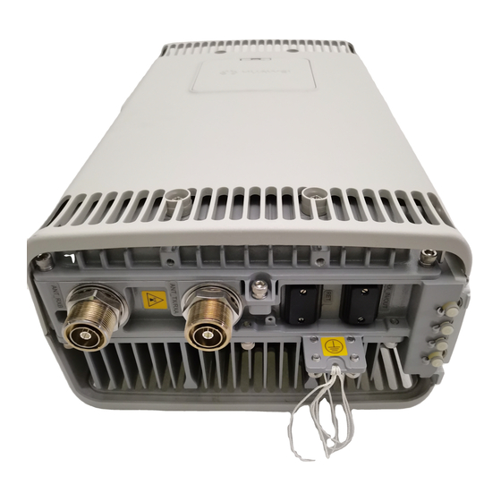
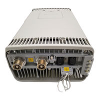
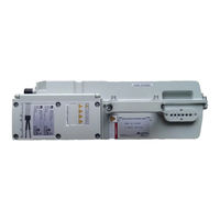
Sign In
Upload
Manuals
Brands
Huawei Manuals
Accessories
RRU3804
Huawei RRU3804 Manuals
Manuals and User Guides for Huawei RRU3804. We have
4
Huawei RRU3804 manuals available for free PDF download: User Manual, Hardware Maintenance Manual
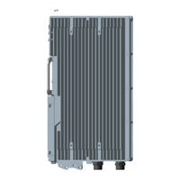
Huawei RRU3804 User Manual (100 pages)
Brand:
Huawei
| Category:
Network Hardware
| Size: 2.23 MB
Table of Contents
Table of Contents
3
Figures
7
Table of Contents
13
About this Document
15
1 Safety Information
19
Safety Precautions
19
Electricity Safety
21
Inflammable Environment
23
Battery
23
Figure 1-1 Wearing an ESD Wrist Strap
23
Radiation
25
Working at Heights
27
Figure 1-2 Lifting a Weight
28
Mechanical Safety
29
Figure 1-3 Slant Angle
29
Figure 1-4 One Meter Higher than the Eave
29
Others
30
2 RRU and SRXU Hardware
33
RRU Equipment
34
Appearance of the RRU
34
Leds on the RRU
35
Table 2-1 Leds on the RRU
35
Panels of the RRU
36
Figure 2-2 Panels of the RRU
37
SRXU Equipment
38
Table 2-2 Ports and Leds on the Panels of the RRU
38
Appearance of the SRXU
39
Leds on the SRXU
39
Table 2-3 Leds on the SRXU
39
Panels of the SRXU
40
Figure 2-4 Panels of the SRXU
41
RRU Cables
42
Table 2-4 Ports and Leds on the Panels of the SRXU
42
PGND Cable of the RRU
43
Power Cable of the RRU
43
Figure 2-5 PGND Cable
43
Figure 2-6 2-Hole Terminal
43
CPRI Optical Cable
44
Figure 2-7 -48 V DC Power Cable
44
Table 2-5 Pin Assignment for the Wires of the -48 V DC Power Cable (North American Standard)
44
Table 2-6 Pin Assignment for the Wires of the -48 V DC Power Cable (European Standard)
44
AISG Multi-Wire Cable of the RRU/SRXU
45
Figure 2-8 CPRI Optical Cable
45
Table 2-7 Pin Assignment for the Fiber Tails of the CPRI Optical Cable
45
Table 2-8 Installation Positions of the CPRI Optical Cable
45
AISG Extension Cable of the RRU/SRXU
46
Figure 2-1 RRU
46
Figure 2-9 AISG Multi-Wire Cable
46
Table 2-9 Pin Assignment for the Wires of the AISG Multi-Wire Cable
46
RF Jumper of the RRU/SRXU
47
Figure 2-10 AISG Extension Cable
47
Table 2-10 Pin Assignment for the Wires of the AISG Extension Cable
47
Figure 2-11 Feeder Jumper
48
Figure 2-12 Interconnect Jumper
49
Table 2-11 RF Jumper Connections of the RRU
49
Alarm Cable of the RRU
50
Figure 2-13 Alarm Cable
50
SRXU Cables
51
Table 2-12 Pin Assignment for the Wires of the Alarm Cable
51
PGND Cable of the SRXU
52
Power Cable of the SRXU
52
Figure 2-14 PGND Cable
52
Figure 2-15 2-Hole Terminal
52
Figure 2-16 DC Power Cable
52
AISG Multi-Wire Cable of the RRU/SRXU
53
Figure 2-17 AISG Multi-Wire Cable
53
Table 2-13 Pin Assignment for the Wires of the DC Power Cable
53
AISG Extension Cable of the RRU/SRXU
54
Figure 2-18 AISG Extension Cable
54
Table 2-14 Pin Assignment for the Wires of the AISG Multi-Wire Cable
54
CPRI Optical Cable
55
Figure 2-19 CPRI Optical Cable
55
Table 2-15 Pin Assignment for the Wires of the AISG Extension Cable
55
RF Jumper of the RRU/SRXU
56
Figure 2-20 Feeder Jumper
56
Table 2-16 Pin Assignment for the Fiber Tails of the CPRI Optical Cable
56
Table 2-17 Installation Positions of the CPRI Optical Cable
56
Figure 2-21 Interconnect Jumper
57
Table 2-18 RF Jumper Connections of the RRU
57
3 Installing RRU and SRXU Hardware
59
Information about the Installation
61
Installation Modes of the RRU and SRXU
61
Figure 3-1 Installation Modes of One RRU
62
Figure 3-2 Installation Modes of One RRU and One SRXU
62
Figure 3-3 Installation Modes of Two Rrus
63
Figure 3-4 Installation Modes of Two Rrus and Two Srxus
63
Space Requirements of the RRU and SRXU
65
Figure 3-6 Installation Modes of Three Rrus and Three Srxus
65
Figure 3-7 Recommended Space Requirements of One RRU with and Without the SRXU (Unit: MM)
66
Figure 3-8 Minimal Space Requirements of One RRU with and Without the SRXU (Unit: MM)
67
Figure 3-9 Space Requirements of Two Combined Rrus (Unit: MM)
67
Figure 3-10 Recommended Space Requirements of Multiple Rrus with and Without the Srxus (Unit: MM)
68
Cabling Specifications for the Nodeb
69
Figure 3-11 Minimal Space Requirements of Multiple Rrus with and Without the Srxus (Unit: MM)
69
Requirements for the RRU Cabling on a Tower
71
Figure 3-12 Scenario of RRU Cabling on a Tower
72
Figure 3-13 PVC Protection Tube
73
Figure 3-14 Installing the Cable Clip
74
Figure 3-15 Routing the Cables in the Cable Rack
75
Figure 3-16 Installing the Cable Clip on the Tower
76
Connections of RRU and SRXU Cables
77
Figure 3-17 Routing the Cables in the Cable Rack
77
Figure 3-18 Cable Connections of One RRU Without the SRXU
78
Figure 3-19 Cable Connections of One RRU with the SRXU
79
Figure 3-20 Cable Connections of Multiple Rrus Without the Srxus
80
Figure 3-21 Cable Connections of Multiple Rrus with the Srxus
80
Labels for DBS3836 Cables
81
Figure 3-22 Label for the BBU Power Cable (Unit: MM)
81
Figure 3-23 Label for the RRU Power Cable (Unit: MM)
81
Figure 3-24 Label for the E1 Cable (Unit: MM)
82
Figure 3-25 Label for the CPRI Optical Cable (Unit: MM)
82
Figure 3-26 Label for the RRU Alarm Cable (Unit: MM)
83
Figure 3-27 Label for the BBU Alarm Cable (Unit: MM)
83
Figure 3-28 Leading Cable Ties through the Holes
83
Procedure for Installing the RRU and SRXU
84
Figure 3-29 Binding the Label to the Cable
84
Preparing for the Nodeb Installation
85
Unpacking Inspection for the Nodeb
85
Tools and Instruments for Nodeb Installation
87
Table 3-1 Tools and Instruments
87
Installing the RRU on the Ground or Rooftop
88
Installing a Single RRU
88
Figure 3-30 Mounting the Upper Fixture Assembly
89
Figure 3-31 Holes in the Fixture Assembly
89
Figure 3-32 Measuring L1 and L2
90
Figure 3-33 Holes in the Multi-Purpose Attachment Plate
90
Figure 3-34 Securing the Multi-Purpose Attachment Plate to the Mounting Plate
91
Figure 3-35 Installing the Third Pole Fixture
91
Figure 3-37 Mounting the Lower Fixture Assembly
93
Figure 3-38 Installed Expansion Bolt Assemblies and the RRU
94
Figure 3-39 Determining the Anchor Points
94
Figure 3-40 Drilling a Hole and Installing the Expansion Bolt Assembly
95
Figure 3-41 Securing the Mounting Plate
96
Figure 3-42 Filling Tube, Insulating Washer, and Insulating Block
96
Figure 3-43 One RRU in Ordinary Mode and the Other in Reverse Mode
97
Figure 3-44 Securing the Attachment Plate
98
Figure 3-45 Installing the Module
99
Figure 3-46 Securing the Module
100
Advertisement
Huawei RRU3804 User Manual (90 pages)
Brand:
Huawei
| Category:
Network Hardware
| Size: 1.72 MB
Table of Contents
Table of Contents
3
Index
2
Figures
7
Table of Contents
11
About this Document
13
Maintaining RRU3804 and SRXU Hardware
13
1 Safety Information
17
Safety Precautions
17
Electricity Safety
19
Inflammable Environment
21
Figure 1-1 Wearing an ESD Wrist Strap
21
Battery
22
Radiation
24
Working at Heights
25
Figure 1-2 Lifting a Weight
26
Mechanical Safety
27
Figure 1-3 Slant Angle
27
Figure 1-4 One Meter Higher than the Eave
27
Others
29
2 RRU3804 and SRXU Hardware
31
RRU3804 Equipment
32
DBS3800 Product Family
32
Figure 2-1 Function Modules of the DBS3800
32
Appearance of the RRU3804
35
Leds on the RRU3804
36
Table 2-1 Leds on the RRU3804
36
Ports on the RRU3804
37
Table 2-2 Power Supply Port on the RRU3804
37
Table 2-3 Transmission Ports on the RRU3804
37
Table 2-4 Alarm Port on the RRU3804
37
Panels of the RRU3804
38
Table 2-5 Specifications for the Alarm Port on the RRU3804
38
Table 2-6 Other Ports on the RRU3804
38
Figure 2-3 Panels of the RRU3804
39
Engineering Specifications of the RRU3804
40
Table 2-7 Ports and Leds on the Panels of the RRU3804
40
SRXU Equipment
41
Appearance of the SRXU
41
Table 2-8 Power Input to the RRU3804
41
Leds on the SRXU
42
Table 2-9 Leds on the SRXU
42
Ports on the SRXU
43
Table 2-10 Power Supply Ports on the SRXU
43
Table 2-11 Transmission Ports on the SRXU
43
Table 2-12 Other Ports on the SRXU
43
Panels of the SRXU
44
Figure 2-5 Panels of the SRXU
44
Engineering Specifications of the SRXU
45
RRU3804 Cables
45
Table 2-13 Ports and Leds on the Panels of the SRXU
45
PGND Cable of the RRU3804
46
Figure 2-6 PGND Cable
46
Figure 2-7 2-Hole Terminal
46
Power Cable of the RRU3804
47
Figure 2-8 -48 V DC Power Cable
47
Table 2-14 Pin Assignment for the Wires of the -48 V DC Power Cable (North American Standard)
47
Table 2-15 Pin Assignment for the Wires of the -48 V DC Power Cable (European Standard)
47
AISG Multi-Wire Cable of the RRU3804/SRXU
48
Figure 2-9 AISG Multi-Wire Cable
48
Table 2-16 Pin Assignment for the Wires of the AISG Multi-Wire Cable
48
AISG Extension Cable of the RRU3804/SRXU
49
Figure 2-10 AISG Extension Cable
49
Table 2-17 Pin Assignment for the Wires of the AISG Extension Cable
49
BBU3806-RRU/SRXU CPRI Optical Cable
50
Figure 2-11 CPRI Optical Cable
50
Table 2-18 Pin Assignment for the Fiber Tails
50
BBU3806C-RRU/SRXU CPRI Optical Cable
51
Figure 2-12 Connecting the CPRI Optical Cable in 1 X 1 Configuration (no TX Diversity)
51
Figure 2-13 Connecting the CPRI Optical Cable in 3 X 1 Configuration (no TX Diversity)
51
Figure 2-14 CPRI Optical Cable
52
Figure 2-15 Connecting the CPRI Optical Cable in 1 X 1 Configuration (no TX Diversity)
52
Table 2-19 Pin Assignment for the Fiber Tails of the CRPI Optical Cable
52
RF Jumper of the RRU3804/SRXU
53
Figure 2-16 Connecting the CPRI Optical Cable in 3 X 1 Configuration (no TX Diversity)
53
Figure 2-17 Antenna Jumper
53
Table 2-20 RF Jumper Connections of the RRU3804
54
Boolean/Rs485 Input Cable of the RRU3804
55
Figure 2-2 RRU3804
55
Figure 2-18 Interconnect Jumper
55
Figure 2-19 Boolean/Rs485 Input Cable
56
Table 2-21 Pin Assignment for the Wires of the Boolean/Rs485 Input Cable
56
SRXU Cables
57
PGND Cable of the SRXU
57
Figure 2-20 PGND Cable
57
Power Cable of the SRXU
58
AISG Multi-Wire Cable of the RRU3804/SRXU
58
Figure 2-21 2-Hole Terminal
58
Figure 2-22 DC Power Cable
58
Table 2-22 Pin Assignment for the Wires of the DC Power Cable
58
AISG Extension Cable of the RRU3804/SRXU
59
Figure 2-23 AISG Multi-Wire Cable
59
Table 2-23 Pin Assignment for the Wires of the AISG Multi-Wire Cable
59
BBU3806-RRU/SRXU CPRI Optical Cable
60
Figure 2-24 AISG Extension Cable
60
Table 2-24 Pin Assignment for the Wires of the AISG Extension Cable
60
Figure 2-25 CPRI Optical Cable
61
Figure 2-26 Connecting the CPRI Optical Cable in 1 X 1 Configuration (no TX Diversity)
61
Table 2-25 Pin Assignment for the Fiber Tails
61
RF Jumper of the RRU3804/SRXU
62
Figure 2-27 Connecting the CPRI Optical Cable in 3 X 1 Configuration (no TX Diversity)
62
Figure 2-28 Antenna Jumper
62
Figure 2-29 Interconnect Jumper
63
3 Installing RRU3804 and SRXU Hardware
65
Information about the Installation
67
Installation Modes of the RRU3804 and SRXU
67
Figure 3-1 Installation Modes of One RRU3804
67
Figure 3-2 Installation Modes of One RRU3804 with One SRXU
68
Figure 3-4 Installation Modes of Two Rru3804S with Two Srxus
69
Figure 3-5 Installation Modes of Three Rru3804S
69
Space Requirements of the RRU3804 and SRXU
70
Figure 3-6 Installation Modes of Three Rru3804S with Three Srxus
70
Figure 3-7 Recommended Space Requirements of One RRU3804 with and Without the SRXU (Unit: MM)
71
Figure 3-8 Minimal Space Requirements of One RRU3804 with and Without the SRXU (Unit: MM)
72
Figure 3-9 Space Requirements of Two Combined Rru3804S (Unit: MM)
72
Figure 3-10 Recommended Space Requirements of Multiple Rru3804S with and Without the Srxus (Unit: MM)
73
Procedure for Installing the RRU3804 and SRXU
74
Figure 3-11 Minimal Space Requirements of Multiple Rru3804S with and Without the Srxus (Unit: MM)
74
Preparing for DBS3800 Installation
75
Unpacking the DBS3800
76
Tools and Instruments for DBS3800 Installation
77
Table 3-1 Tools and Instruments
77
Installing the RRU3804 on the Ground or Rooftop
78
Installing a Single RRU3804
78
Figure 3-12 Mounting the Upper Fixture Assembly
79
Figure 3-13 Measuring L1 and L2
80
Figure 3-14 Holes in the Multi-Purpose Attachment Plate
80
Figure 3-15 Securing the Multi-Purpose Attachment Plate on the Mounting Plate
81
Figure 3-16 Installing the Third Pole Fixture
81
Figure 3-18 Mounting the Lower Fixture Assembly
83
Figure 3-19 Determining the Anchor Points
84
Figure 3-20 Drilling Holes and Installing the Expansion Bolt Assembly
84
Figure 3-21 Securing the Mounting Plate
85
Figure 3-22 One RRU3804 in Ordinary Mode and the Other in Reverse Mode
86
Figure 3-23 Securing the Attachment Plate
87
Figure 3-24 Installing the Module
88
Installing Two Rru3804S
89
Figure 3-25 Securing the Module
89
Figure 3-26 Holes in the Multi-Purpose Attachment Plate
90
Figure 3-27 Securing the Multi-Purpose Attachment Plate at the Bottom of the Second Mounting Plate
90
Huawei RRU3804 Hardware Maintenance Manual (58 pages)
Brand:
Huawei
| Category:
Accessories
| Size: 1.28 MB
Table of Contents
About this Document
3
Intended Audience
3
Conventions
4
Organization
4
Symbol Conventions
4
Command Conventions
5
General Conventions
5
GUI Conventions
6
Keyboard Operation
6
Mouse Operation
6
Table of Contents
7
1 Changes in RRU Hardware Maintenance Guide
8
2 Preventative Maintenance Items for an RRU
15
3 Powering on and off an RRU
17
Powering off an RRU
18
4 Replacing an RRU
20
Preparations before Replacement
20
Replacing an RRU Using Assembled Mounting Kits
22
Replacing an RRU Using a Mounting Kit for a Common RRU
22
Attachment Plate a for a Common RRU
23
Attachment Plate B for a Common RRU
23
Loosening Captive Screws on the Main Bracket
25
Loosening the Screw Only for Removing the RRU on the Attachment Plate
25
Raising the Bottom of the RRU
26
Replacing an RRU Using a Mounting Kit for a Blade RRU
27
Removing the Metal Sheet from an RRU Installed in Centralized Mode
29
Loosening Captive Screws on the Attachment Plate
29
Replacing an RRU Using Non-Assembled Mounting Kits
30
Loosening Screws on the Conversion Bracket (Blade RRU)
32
Loosening Screws on the Conversion Bracket (Non-Blade RRU)
32
Holding the RRU Upwards (Blade RRU)
33
Holding the RRU Upwards (Non-Blade RRU)
33
Replacing a Non-Blade RRU with a Blade RRU
34
Replace the RRU in the Middle
36
Reusing the Conversion Bracket
36
Waterproofing a Connector of the Alarm Cable
39
Replacing Blade Rrus in the ICR and Adding Blade Rrus to the ICR
40
Loosing the Upper and Lower Installation Plates
41
Removing the Attachment Plate from the Rear of the RRU
42
Removing the Handle from the RRU
42
Installing the Upper Attachment Plate on the Upper Part of the RRU
43
Installing the Lower Attachment Plate on the Lower Part of the RRU
43
Installing the RRU in an ICR
44
ICR Housing Three Rrus
45
Operations after Replacement
45
5 Replacing an Optical Module
47
6 Adding Rrus
50
Attaching a Blade RRU
53
Installing the Third RRU on the Third Main Bracket
54
Installing the Second Mounting Kit for a Blade RRU
54
Installing a Blade RRU on the Fourth Main Bracket
55
Tightening the Captive Screws into the Holes
56
Installing a Metal Sheet
56
Advertisement
Huawei RRU3804 User Manual (46 pages)
Brand:
Huawei
| Category:
Accessories
| Size: 1.01 MB
Table of Contents
Table of Contents
3
About this Document
9
1 Changes in the RRU3804 User Guide
13
2 DBS3900 Hardware Configuration
15
Typical Configurations of the DBS3900
16
Table 2-1 Typical Configurations of the DBS3900
16
Figure 2-1 Cable Connections of the DBS3900 in Type 3 X 1 Configuration
17
4-Way RX Diversity Configuration
18
Figure 2-2 Cable Connections of the DBS3900 in Type 3 X 4 Configuration
18
Table 2-2 Number of Modules in the DBS3900 in 4-Way RX Diversity Configuration
19
TX Diversity Configuration
20
Figure 2-3 Cable Connections of the DBS3900 in 4-Way RX Diversity Configuration
20
Table 2-3 Number of Modules in the DBS3900 in TX Diversity Configuration
21
X 2 MIMO Configuration
22
Figure 2-4 Cable Connections of the DBS3900 in TX Diversity Configuration
22
Table 2-4 Number of Modules in the DBS3900 in 2 X 2 MIMO Configuration
23
Figure 2-5 Cable Connections of the DBS3900 in 2 X 2 MIMO Configuration
24
3 RRU Hardware
25
RRU Equipment
26
Appearance of the RRU3804
26
Figure 3-1 Appearance of the RRU3804
26
Panels of the RRU3804
27
Figure 3-2 Panels of the RRU3804
27
Leds on the RRU3804
28
Table 3-1 Ports and Leds on the Panels of the RRU3804
28
Table 3-2 Leds on the RRU3804
28
RRU Cables
29
RRU3804 Cable List
30
Table 3-3 RRU3804 Cable List
30
PGND Cable of the RRU
31
Figure 3-3 PGND Cable
31
Power Cable of the RRU
32
Figure 3-4 2-Hole Terminal
32
Figure 3-5 -48 V DC Power Cable
32
Table 3-4 Pin Assignment for the Wires of the -48 V DC Power Cable (North American Standard)
32
CPRI Optical Cable
33
Figure 3-6 CPRI Optical Cable
33
Table 3-5 Pin Assignment for the Wires of the -48 V DC Power Cable (European Standard)
33
AISG Multi-Wire Cable of the RRU
34
Figure 3-7 AISG Multi-Wire Cable
34
Table 3-7 Pin Assignment for the Fiber Tails of the CPRI Optical Cable between Rrus
34
AISG Extension Cable of the RRU
35
Figure 3-8 AISG Extension Cable
35
Table 3-8 Pin Assignment for the Wires of the AISG Multi-Wire Cable
35
RF Jumper of the RRU
36
Figure 3-9 Antenna Jumper
36
Table 3-9 Pin Assignment for the Wires of the AISG Extension Cable
36
Figure 3-10 Interconnect Jumper
37
Table 3-10 RF Jumper Connections of the RRU
37
Alarm Cable of the RRU
38
Figure 3-11 Alarm Cable
39
Table 3-11 Pin Assignment for the Wires of the Alarm Cable
39
4 Maintaining the Hardware of the RRU
41
Maintenance Items of the RRU
42
Powering on and Powering off the RRU
42
Powering on the RRU
42
Table 4-1 Maintenance Items of the RRU
42
Powering off the RRU
43
Replacing the RRU
44
Replacing an Optical Module
45
Figure 4-1 Removing an RRU
45
Advertisement
Related Products
Huawei RRU3808
Huawei RRU3806
Huawei RRU3805
Huawei RRU3828
HUAWEI RRU3232
Huawei RRU3222
Huawei RRU3901E
Huawei RRU3942
Huawei BSS7.0 RRU3606
Huawei RRU3008 DC V2
Huawei Categories
Cell Phone
Network Router
Wireless Router
Modem
Network Hardware
More Huawei Manuals
Login
Sign In
OR
Sign in with Facebook
Sign in with Google
Upload manual
Upload from disk
Upload from URL