Table of Contents
Advertisement
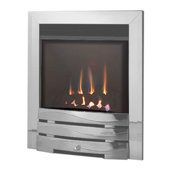
Evora Slide Control
- Modular Coal & Modular Pebble Effect
- Inset Live Fuel Effect Radiant Convector Fire
Installation and
Users Instructions
These instructions should be read by the
installer before installation and then should be
handed to the end user when the installation
is complete.
This is an official requirement and is the
responsibility of the fitter of this
appliance.
Having installed the appliance, the installer
should take the necessary steps to ensure
that the user fully understands how to operate
the appliance and is also made aware of the
fire's basic cleaning and maintenance
requirements.
Advertisement
Table of Contents

Related Manuals for Legendfires Evora


Summary of Contents for Legendfires Evora
- Page 1 Evora Slide Control - Modular Coal & Modular Pebble Effect - Inset Live Fuel Effect Radiant Convector Fire Installation and Users Instructions These instructions should be read by the installer before installation and then should be handed to the end user when the installation is complete.
-
Page 2: Table Of Contents
CONTENTS SECTION PAGE Notes for the Installer and End User Installation Requirements Installation Procedure Commissioning Technical Data Replacement Parts Trouble Shooting (GAS SAFE Engineer Only) 8 User Instructions Cleaning and Maintenance Fire Front Specifications Modular Coal Layout Instructions Modular Pebble Layout Instructions Guarantee Trouble Shooting (User) -
Page 3: Notes For The Installer And End User
NOTES FOR THE INSTALLER AND END USER This appliance has been designed, tested and manufactured to the British Standard BS 7977-1:2002 relating to Radiant Convector Gas Appliances and must be installed by a qualified Gas Safe Registered Installer in accordance with the Gas Safety (Installation and use) regulations 1994 and all other relevant standards. This appliance must be connected in accordance with the National Regulations. -
Page 4: Installation Requirements
INSTALLATION REQUIREMENTS This appliance must only be installed in Great Britain or Ireland. 1. This fire is a natural gas appliance and has been designed for use with the following applications: a) Class I - Conventional brick or stone chimney as used for a solid fuel fire with a cross sectional dimension of 225mm x 225mm (9”... -
Page 5: Installation Procedure
INSTALLATION PROCEDURE 1. Carefully lift the appliance out of the packaging taking care not to damage the ceramic components in the separate carton. 2. Remove the magnetic trim and store to one side to prevent any damage. 5 x Machine Screws 3. - Page 6 INSTALLATION PROCEDURE CONTINUED 9. When the burner tray has been removed, decide which Fixing Holes side of the appliance the gas supply will be entering the radiant box and remove the relevant blanking plate. The gas supply should be concealed as much as possible. Both blanking plates MUST be re-fitted or this could seriously impair performance.
-
Page 7: Commissioning
COMMISSIONING 1. Unscrew the inlet pressure test point sealing screw (Fig. 7) and fit a manometer. Consult the user instructions (page 9). Ignite the appliance and turn to the high position. 2. Take a pressure reading and consult the technical data (page 7) to establish the correct working pressure. -
Page 8: Trouble Shooting (Gas Safe Engineer Only)
TROUBLE SHOOTING (GAS SAFE ENGINEER ONLY) 1. The Piezo will not spark. Check: If the electrode is cracked or broken - Replace pilot assembly. If the HT lead is shorting out on the burner body - Locate where the short is occurring, isolate and/or re-route the lead. -
Page 9: User Instructions
USER INSTRUCTIONS Please also familiarise yourself with the Notes for the Installer and End User on page 3. Never place combustible material directly in front of this appliance. Floor covering such as carpet is acceptable but must be a minimum of 300mm from the incandescent flame. Any combustible shelf must be at least 215mm above the fire trim, providing the shelf depth is 150mm or less. -
Page 10: Cleaning And Maintenance
CLEANING AND MAINTENANCE Legend Gas Fires recommend that this appliance is serviced at regular 12 monthly intervals. The chimney or flue should also be checked regularly to ensure that all products of combustion are entering the flue and there is no excessive build up of soot. It is the users responsibility to ensure that the appliance is kept in a clean serviceable condition. -
Page 11: Fire Front Specifications
CLEANING AND MAINTENANCE CONTINUED Slide Control Lever - The slide control mechanism should be greased annually with high temperature grease. Place a small amount of grease at the top and bottom of the lever guide and operate the lever several times to work the grease into the guide. -
Page 12: Modular Coal Layout Instructions
MODULAR COAL LAYOUT INSTRUCTIONS CAUTION: The coals are extremely fragile and must be handled accordingly. Gloves should be worn and any inhalation of dust should be avoided. The coals must be kept away from children at all times. Never put additional coals on the fire. Never use coals other than those originally supplied, or genuine Legend Spare Parts. - Page 13 MODULAR COAL LAYOUT INSTRUCTIONS CONTINUED 5. Finally check that all the coal pieces are ‘nested’ together correctly (Fig. 18) and a close fit is achieved on the middle joint (this will stop gas surge through the gap). Fig. 18 It is very important that all the coals are used and arranged as shown in order to achieve the desired flame picture.
-
Page 14: Modular Pebble Layout Instructions
MODULAR PEBBLE LAYOUT INSTRUCTIONS CAUTION: The pebbles are extremely fragile and must be handled accordingly. Gloves should be worn and any inhalation of dust should be avoided. The pebbles must be kept away from children at all times. Never put additional pebbles on the fire. Never use pebbles other than those originally supplied, or genuine Legend Spare Parts. - Page 15 MODULAR PEBBLE LAYOUT INSTRUCTIONS CONTINUED 5. Finally check that all the pebble pieces are ‘nested’ together correctly (Fig. 24) and a close fit is achieved on the middle joint (this will stop gas surge through the gap). Fig. 24 It is very important that all the pebbles are used and arranged as shown in order to achieve the desired flame picture.
-
Page 16: Guarantee
GUARANTEE Your appliance is guaranteed for one year from proof of purchase. Should the appliance prove defective within that period we agree to repair or replace (at our discretion) the component or appliance provided that: 1. The user can produce a receipt for proof of purchase/installation. 2.
Need help?
Do you have a question about the Evora and is the answer not in the manual?
Questions and answers