Table of Contents
Advertisement
FILE NO. A11-011
Revision 1 : Jun., 2017
SERVICE MANUAL
AIR-CONDITIONER
(MULTI TYPE)
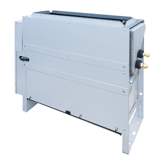
Medium Static Ducted Type
MMD- AP0074BH2UL
MMD- AP0094BH2UL
MMD- AP0124BH2UL
MMD- AP0154BH2UL
MMD- AP0184BH2UL
MMD- AP0214BH2UL
MMD- AP0244BH2UL
MMD- AP0304BH2UL
MMD- AP0364BH2UL
MMD- AP0424BH2UL
MMD- AP0484BH2UL
MMD- AP0484BH2UL
R410A
PRINTED IN JAPAN, Nov., 2011 ToMo
Advertisement
Table of Contents

Related Manuals for Toshiba Carrier MMD- AP0074BH2UL


Summary of Contents for Toshiba Carrier MMD- AP0074BH2UL
- Page 1 FILE NO. A11-011 Revision 1 : Jun., 2017 SERVICE MANUAL AIR-CONDITIONER (MULTI TYPE) Medium Static Ducted Type MMD- AP0074BH2UL MMD- AP0094BH2UL MMD- AP0124BH2UL MMD- AP0154BH2UL MMD- AP0184BH2UL MMD- AP0214BH2UL MMD- AP0244BH2UL MMD- AP0304BH2UL MMD- AP0364BH2UL MMD- AP0424BH2UL MMD- AP0484BH2UL MMD- AP0484BH2UL R410A PRINTED IN JAPAN, Nov., 2011 ToMo...
-
Page 2: Table Of Contents
CONTENTS SAFETY CAUTION ................3 1. SPECIFICATIONS ............... 8 2. CONSTRUCTION VIEWS (EXTERNAL VIEWS) ......9 3. WIRING DIAGRAM..............12 4. PARTS RATING ................. 13 5. REFRIGERATIN GCYCLE DIAGRAM........14 6. CONTROL OUTLINE ..............15 7. APPLIED CONTROL AND FUNCTION ........22 8. -
Page 3: Safety Caution
SAFETY CAUTION The important contents concerned to the safety are described on the product itself and on this Service Manual. Please read this Service Manual after understanding the described items thoroughly in the following contents (Indications/Illustrated marks), and keep them. The manufacturer shall not assume any liability for the damage caused by not observing the description of this manual. - Page 4 WARNING Before troubleshooting or repair work, check the earth wire is connected to the earth terminals of the main unit, otherwise an electric shock is caused when a leak occurs. If the earth wire is not correctly connected, contact an electric engineer for rework. Check earth wires.
- Page 5 WARNING After the work has finished, be sure to use an insulation tester set (500V Megger) to check the resistance is 2MΩ or more between the charge section and the non-charge metal section (Earth position). If the resistance value is low, a disaster such as a leak or electric shock is caused at user’s Insulator check side.
- Page 6 • New Refrigerant (R410A) This air conditioner adopts a new HFC type refrigerant (R410A) which does not deplete the ozone layer. 1. Safety Caution Concerned to New Refrigerant The pressure of R410A is high 1.6 times of that of the former refrigerant (R22). Accompanied with change of refrigerant, the refrigerating oil has been also changed.
- Page 7 4. Tools 1. Required Tools for R410A Mixing of different types of oil may cause a trouble such as generation of sludge, clogging of capillary, etc. Accordingly, the tools to be used are classified into the following three types. 1) Tools exclusive for R410A (Those which cannot be used for conventional refrigerant (R22)) 2) Tools exclusive for R410A, but can be also used for conventional refrigerant (R22) 3) Tools commonly used for R410A and for conventional refrigerant (R22) The table below shows the tools exclusive for R410A and their interchangeability.
-
Page 8: Specifications
1. SPECIFICATIONS 1-1. Medium Static Ducted Type MMD-AP0074BH2UL, AP0094BH2UL, AP0124BH2UL, AP0154BH2UL, AP0184BH2UL Model name MMD- AP0074BH2UL AP0094BH2UL AP0124BH2UL AP0154BH2UL AP0184BH2UL Cooling Capacity kBtu/h 15.4 Heating Capacity kBtu/h 10.5 13.5 Electrical Power supply 230 V (208/230V) 1phase 60Hz characteristics Power consumption 0.041 0.041 0.049... -
Page 9: Construction Views (External Views)
³ 2. CONSTRUCTION VIEWS (EXTERNAL VIEWS) 2-1. Medium Static Ducted Type MMD- AP0074BH2UL, MMD- AP0094BH2UL, MMD- AP0124BH2UL – 9 –... - Page 10 MMD- AP0154BH2UL, MMD- AP0184BH2UL – 10 –...
- Page 11 MMD- AP0214BH2UL, MMD- AP0244BH2UL, MMD- AP0304BH2UL, MMD- AP0364BH2UL MMD- AP0424BH2UL, MMD- AP0484BH2UL – 11 –...
-
Page 12: Wiring Diagram
3. WIRING DIAGRAM – 12 –... -
Page 13: Parts Rating
4. PARTS RATING Model MMD-AP 0074BH2UL 0094BH2UL 0124BH2UL 0154BH2UL 0184BH2UL Fan motor MF-240U150-2A MF-240U150-1A Drain pump motor ADP-1406 Float switch FS-0218-102 Pulse motor EFM-MD12TF-1 Pulse motor valve EFM-25YGTF-1 EFM-40YGTF-1 Reactor CH-43-2Z-T TA sensor Lead wire length : 24.3 in (618mm) TC1 sensor Ø4, Lead wire length : 47.2 in (1200mm), Vinyl tube (Blue) TC2 sensor... -
Page 14: Refrigeratin Gcycle Diagram
5. REFRIGERATING CYCLE DIAGRAM Liquid side Gas side Strainer Capillary tube Air heat exchanger at indoor side Pulse Motor Valve (PMV) Strainer Sensor (TCJ) Sensor (TC2) Sensor (TC1) Sensor Fan motor (TA) Functional part name Functional outline Pulse Motor Valve (Connector CN082 (6P): Blue) 1) Controls super heat in cooling operation 2) Controls under cool in heating operation... -
Page 15: Control Outline
6. CONTROL OUTLINE Item Outline of specifications Remarks When power 1) Distinction of outdoor unit supply is reset When the power supply is reset, the outdoors are distinguished and the control is selected according to the distinguished result. 2) Setting of indoor fan speed and existence of air direction adjustment Based on EEPROM data, select setting of the indoor fan Air speed (rpm)/... - Page 16 Item Outline of specifications Remarks Automatic 1) Based on the difference between Ta and Ts, the capacity control operation capacity is determined by the outdoor unit. COOL HEAT ˚F (˚C) ˚F (˚C) +3.6 (+2) +1.8 (+1) +1.8 (+1) Ts: Setup temp. Ta: Room temp.
- Page 17 Item Outline of specifications Remarks Air speed <HEAT> selection (Continued) Ta ˚F (˚C) L <L+> (–0.9) –1.8 [(–0.5) –1.0] L+ <H> (0) Tsh H <H+> (+0.9) +1.8 [(+0.5) +1.0] <HH> (+1.8) +3.6 [(+1.0) +2.0] (+2.7) +5.4 [(+1.5) +3.0] <HH> (+3.6) +7.2 [(+2.0) +4.0] <...
- Page 18 Item Outline of specifications Remarks Freeze prevention 1. In all cooling operation, the air conditioner TC1: Temperature of indoor control operates as de-scribed below based upon temp. heat exchanger sensor (Low temp. release) detected by TC1, TC2 and TCJ sensors. •...
- Page 19 Item Outline of specifications Remarks Recovery control The indoor unit which is under STOP/Thermo-OFF • The indoor unit which is for heating status or which operates in [FAN] mode performs the under thermo-OFF (COOL) refrigerant (Oil) following controls when it received the heating status or which operates in refrigerant (Oil) recovery signal from the outdoor unit.
- Page 20 Item Outline of specifications Remarks Display of < READY> Displayed on the remote controller • <READY > display [READY] 1) When the following check codes are indicated No display for wireless [HEAT READY] type remote controller • Open phase of power supply wiring [P05] was detected. •...
- Page 21 Item Outline of specifications Remarks DC motor 1) When the fan stator, positioning is performed for the Check code [P12] starter and the rotor. (Vibrate slightly) 2) DC motor operates according to the command from the indoor controller. (Note) If the fan rotates by entry of outside air, etc while the air conditioner stopped, the indoor unit may operate as the fan motor stops.
-
Page 22: Applied Control And Function
7. APPLIED CONTROL AND FUNCTION 7-1. Indoor Controller Block Diagram 7-1-1. When Main (Simple) Wired Remote Controller Connected Main (Simple) wired remote controller (Up to 2 sets) Display part Function setup Key switch Display part DC5V Power circuit Remote controller communication circuit Indoor unit Main P.C. - Page 23 7-1-2. When Wireless Remote Controller Kit Connected – 23 –...
- Page 24 7-1-3. When Both Wired (Simple) Remote Controller and Wireless Remote Controller Kit Connected – 24 –...
- Page 25 7-1-4. Indoor Printed Circuit Board MCC-1510 TC2 sensor TCJ sensor Microcomputer operation LED CN101, DC 5V CN102, DC 5V TC1 sensor Power supply CN100, DC5V CN67 HA (T10) CN61, DC 12V Drain pump power supply Option output CN309 CN60, DC 12V AC 208/230V CN71, DC 5V DISP...
- Page 26 P.C. Board Optional Switch/Connector Specifications Connector Function Specifications Remarks Turn the switch to ON, when using the external static pressure function. No use Bit 1 SW01 SW01 <Bit 2> Input Bit 2 External static SW02 pressure <Bit 2> No use Bit 1 0.008 psi (55 Pa) 0.013 psi...
- Page 27 7-2. Functions at test run Cooling/Heating test run check The test run for cooling/heating can be performed from either indoor remote controller or outdoor interface P.C. board. 1. Start/Finish operation of test run Test run from indoor remote controller Wired remote controller: Refer to the below item of “Test run” of the wired remote controller. Wireless remote controller: Refer to the next page item of “Test run”...
- Page 28 <In case of wireless remote controller (TCB-AX21UL)> Procedure Description Turn on power of the air conditioner. The operation is not accepted for 5 minutes when power has been turned on at first time after installation, and 1 minute when power has been turned on at the next time and after. After the specified time has passed, perform a test operation.
- Page 29 Check function for operation of indoor unit (Functions at indoor unit side) This function is provided to check the operation of the indoor unit singly without communication with the remote controller or the outdoor unit. This function can be used regardless of operation or stop of the system. However, if using this function for a long time, a trouble of the equipment may be caused.
- Page 30 7-3. Method to Set Indoor Unit Function DN Code (When performing this task, be sure to use a wired remote controller.) <Procedure> To be performed only when system at rest Push the buttons simultaneously and hold for at least 4 seconds. The unit No.
- Page 31 Functio n CODE No. (DN Code) Table (Includes All Functions Needed to Perform Applied Control on Site) Item Descrip tio n At sh ip men t Filter display delay timer 0000: None 0001: 150H According to type 0002: 2500H 0003: 5000H 0004: 10000H Dirty state of filter 0000: Standard...
- Page 32 Item Description At shipment 0003 0001 SET DATA 0000 0006 0.008psi (55Pa) 0.013psi (90Pa) 0.017psi (120Pa) 0.006psi (40Pa) External static Standard pressure High static pressure 1 High static pressure 3 Low static pressure (Factory default) SW01 SW02 SW01 SW02 SW01 SW02 SW01 SW02...
- Page 33 7-4. Applied Control in Indoor Unit Remote location ON/OFF control box (TCB-IFCB-4UL) [Wiring and setup] • Use the exclusive connector for connection with the indoor control P.C. board. • In a group control, the system can operate when connecting with any indoor unit (Control P.C. board) in the group.
- Page 34 Ventilating fan control from remote controller [Function] • The start/stop operation can be operated from the wired remote controller when air to air heat exchanger or ventilating fan is installed in the system. • The fan can be operated even if the indoor unit is not operating. •...
- Page 35 Leaving-ON prevention control [Function] • This function controls the indoor units individually. It is connected with cable to the control P.C. board of the indoor unit. • In a group control, it is connected with cable to the indoor unit (Control P.C. board), and the CODE No. is set to the connected indoor unit.
- Page 36 Address setup (Manual setting from Wired remote controller) In case that addresses of the indoor units will be determined prior to piping work after wiring work • Set an indoor unit per a remote controller. (Example of 2-lines cabling) (Real line: Wiring, Broken line: Refrigerant pipe) •...
- Page 37 Confirmation of indoor unit No. position 1. To know the indoor unit addresses though position of the indoor unit is recognized • In case of individual operation (Wired remote controller : indoor unit = 1 : 1) (Follow to the procedure during operation) <Procedure>...
- Page 38 How to check all the unit No. from an arbitrary wired remote controller <Procedure> Carry out this procedure during stop of system. The indoor unit No. and the position in the identical refrigerant piping can be checked. An outdoor unit is selected, the identical refrigerant piping and the indoor unit No. are displayed one after the other, and then its fan and louver are on.
- Page 39 How to change an indoor unit address by using a wired remote control Use this method to change the address of indoor units (one to one or group control) that have had the original address set automatically. This procedure must be done while the units are not operating. TEST Simultaneously push and hold the “SET ”, “CL...
- Page 40 How to change all indoor addresses from an arbitrary wired remote controller (It is possible when setting has finished by automatic addresses.) Contents: The indoor unit addresses in each identical refrigerant piping line can be changed from an arbitrary wired remote controller. Enter in address check/change mode and then change the address.
- Page 41 Function to clear error 1. Clearing method from remote controller How to clear error of outdoor unit In the unit of refrigerant line connected by indoor unit of the remote controller to be operated, the error of the outdoor unit currently detected is cleared. (Error of the indoor unit is not cleared.) The service monitor function of the remote controller is utilized.
- Page 42 Monitoring function of remote controller switch When using the remote controller (Model Name: RBC-AMT32UL), the following monitoring function can be utilized. Calling of display <Contents> The temperature of each sensor of the remote controller, indoor unit and outdoor unit and the operating status can be checked by calling the service monitor mode from the remote controller.
- Page 43 CODE No. Data name Display format Unit Remote controller display example Room temperature (During control) ×1 °F [0081]=71°F(27°C) Room temperature (Remote controller) ×1 °F Indoor suction temperature (TA) ×1 °F Indoor coil temperature (TCJ) ×1 °F Indoor coil temperature (TC2) ×1 °F [0075]=75°F(24°C)
- Page 44 Changing of settings for Celsius display ON / OFF • Push button if the unit stops. Procedure TEST Push simultaneously buttons for 4 seconds or more. After a while, the display part flashes as shown right. Check the displayed CODE No. is [ TEST •...
-
Page 45: Troubleshooting
8. TROUBLESHOOTING 8-1. Overview (1) Before engaging in troubleshooting (a) Applicable models All Super Module Multi (SMMS-i) models. (Indoor units: MMD-APOOO, Outdoor units: MMY-MAPOOO4HT9UL) (b) Tools and measuring devices required • Screwdrivers (Philips, flat head), spanners, long-nose pliers, nipper, pin to push reset switch, etc. •... - Page 46 8-2. Troubleshooting Method The remote controllers (main remote controller and central control remote controller) and the interface P.C. board of an outdoor unit are provided with an LCD display (remote controller) or a 7-segment display (outdoor interface P.C. board) to display operational status. Using this self-diagnosis feature, the fault site/faulty part may be identified in the event of a fault by following the method described below.
- Page 47 (Error detected by main remote controller) Check code Display of receiving unit Outdoor 7-segment display Indicator light block Typical fault site Description of error Main remote controller Operation Timer Ready Flash Sub-code No master remote controller, Signals cannot be received from indoor unit; –...
- Page 48 IPDU: Intelligent Power Drive Unit (Inverter P.C. board) List of Check Codes (Outdoor Unit) : Lighting, : Flashing, : Goes off (Errors detected by SMMS-i outdoor interface - typical examples) ALT.: Flashing is alternately when there are two flashing LED SIM: Simultaneous flashing when there are two flashing LED Check code Display of receiving unit...
- Page 49 Check code Display of receiving unit TCC-LINK Outdoor 7-segment display Indicator light block central control Typical fault site Description of error or main remote Operation Timer Ready controller Flash Sub-code display Outdoor suction Outdoor suction temperature sensor (TS1) has – temperature sensor (TS1) been open/short-circuited.
- Page 50 Check code Display of receiving unit TCC-LINK Outdoor 7-segment display Indicator light block central control Typical fault site Description of error or main remote Operation Timer Ready controller Flash Sub-code display A3-IPDU Fan A3-IPDU IPDU IPDU There are insufficient number of IPDUs (P.C. SIM Error in number of IPDUs boards) in inverter box.
- Page 51 (Errors detected by IPDU featuring in SMMS-i standard outdoor unit - typical examples) Check code Display of receiving unit TCC-LINK Outdoor 7-segment display Indicator light block central control Typical fault site Description of error or main remote Operation Timer Ready controller Flash Sub-code...
- Page 52 8-3. Troubleshooting Based on Information Displayed on Remote Controller Using main remote controller (RBC-AMT32UL) (1) Checking and testing When a fault occurs to an air conditioner, a check code and indoor unit No. are displayed on the display window of the remote controller. Check codes are only displayed while the air conditioner is in operation.
- Page 53 Using indoor unit indicators (receiving unit light block) (wireless type) To identify the check code, check the 7-segment display on the header unit. To check for check codes not displayed on the 7-segment display, consult the “List of Check Codes (Indoor Unit)” in “8-2. Troubleshooting Method”.
- Page 54 Light block Check code Cause of fault Heat exchanger temperature sensor (TCJ) error Operation Timer Ready Heat exchanger temperature sensor (TC2) error Indoor unit temperature sensor Heat exchanger temperature sensor (TC1) error errors Ambient temperature sensor (TA) error Alternate blinking Discharge temperature sensor (TF) error Discharge temperature sensor (TD1) error Operation Timer...
- Page 55 Light block Check code Cause of fault Operation Timer Ready Outdoor EEPROM error Synchronized blinking Other (indications not involving check code) Light block Check code Cause of fault Operation Timer Ready – Test run in progress Synchronized blinking Operation Timer Ready Setting incompatibility –...
- Page 56 8-4. Check Codes Displayed on Remote Controller and SMMS-i Outdoor Unit (7-Segment Display on I/F Board) and Locations to Be Checked For other types of outdoor units, refer to their own service manuals. Check code Location Error detection Outdoor 7-segment display Description System status Check items (locations)
- Page 57 Check code Location Outdoor 7-segment display Error detection Description System status Check items (locations) Main condition(s) remote detection Check code controller Sub-code Duplicated Indoor Duplicated All stop More than one indoor unit is • Check indoor addresses. indoor address unit indoor address assigned same address.
- Page 58 Check code Location Outdoor 7-segment display Error detection Description System status Check items (locations) Main condition(s) detection remote Check code Sub-code controller Indoor Error in Stop of Periodic communication • Check remote controller unit communication corresponding between indoor header and wiring.
- Page 59 Check code Location Outdoor 7-segment display Error detection Description System status Check items (locations) Main condition(s) remote detection Check code Sub-code controller IPDU All stop Communication is disrupted • Check wiring and A3-IPDU Fan communication between IPDUs (P.C. connectors involved in IPDU error boards) in inverter box.
- Page 60 Check code Location Outdoor 7-segment display System Error detection Description Check items (locations) Main status condition(s) remote detection Sub-code controller Check code TO sensor All stop Sensor resistance is infinity • Check connection of TO error or zero (open/short circuit). sensor connector.
- Page 61 Check code Location Outdoor 7-segment display System Error detection Description Check items (locations) Main status condition(s) remote detection controller Sub-code Check code Indoor Other indoor Stop of Indoor P.C. board does not • Check for defect in indoor P.C. – –...
- Page 62 Check code Location Outdoor 7-segment display Error detection Description System status Check items (locations) Main condition(s) detection remote Check code Sub-code controller Low oil level All stop Operating compressor <All outdoor units in protection detects continuous state of corresponding line to be low oil level for about 2 hours.
- Page 63 Check code Location Outdoor 7-segment display System Error detection Description Check items (locations) Main status condition(s) remote detection Check code Sub-code controller 01: TK1 oil Oil level All stop No temperature • Check for disconnection of TK1 sensor. circuit error detection change is detected •...
- Page 64 Check code Location Outdoor 7-segment display Error detection Description System status Check items (locations) Main condition(s) detection remote Check code Sub-code controller Indoor Duplicated Stop of There is more than one • Check indoor addresses. unit indoor header corresponding header unit in group. •...
- Page 65 Check code Location Error detection Outdoor 7-segment display Description System status Check items (locations) Main condition(s) remote detection Check code Sub-code controller Error in No. of All stop Insufficient number of IPDUs • Check model setting of A3-IPDU Fan IPDUs are detected when power is P.C.
- Page 66 Check code Location System Error detection Outdoor 7-segment display Description Check items (locations) Main status condition(s) remote detection Check code Sub-code controller 01: Compressor IPDU Activation of high- All stop High-pressure SW is • Check connection of high- 1 side pressure SW activated.
- Page 67 Check code Location Outdoor 7-segment display Error detection Description System status Check items (locations) Main condition(s) detection remote Check code Sub-code controller Outdoor liquid All stop <During cooling operation> • Check full-close operation backflow When system is in cooling of outdoor PMV (1, 2, 4). detection error operation, high pressure is •...
- Page 68 Check code Location Outdoor 7-segment display Error detection Main Description System status Check items (locations) condition(s) remote detection controller Check code Sub-code Detected 4-way valve All stop Abnormal refrigerating cycle • Check for defect in main outdoor unit reversing error data is collected during body of 4-way valve.
- Page 69 Check code Location Outdoor 7-segment display Error detection AI-NET central Description System status Check items (locations) Main control condition(s) remote detection Check remote Sub-code controller code controller 0 : IGBT circuit IPDU Outdoor fan All stop (Sub code: 0 ) •...
- Page 70 Errors Detected by TCC-LINK Central Control Device Check code Location Error detection Outdoor 7-segment display Description System status Check items (locations) Main condition(s) remote detection controller Sub-code TCC-LINK TCC-LINK Continued Central control device is • Check for defect in central central control operation unable to transmit signal.
- Page 71 8-5. Sensor Characteristics Indoor Unit Temperature sensor characteristics Temperature Resistance [˚F (˚C)] [kΩ] Resistance 32 (0) 33.9 [kΩ] 41 (5) 26.1 50 (10) 20.3 59 (15) 15.9 68 (20) 12.6 77 (25) 10.0 86 (30) 95 (35) 104 (40) 113 (45) 122 (50) 131 (55) 140 (60)
-
Page 72: Detachments
9. DETACHMENTS CAUTION WARNING Be sure to put on the gloves at disassembling Be sure to turn off the power supply and the work; otherwise an injury will be caused by a breaker and then start a work. part, etc. Part name Procedure Remarks... - Page 73 Part name Procedure Remarks Cable clamp ∗ ∗ ∗ ∗ ∗ Cautions when attaching the electric parts box Using cable clamp, bundle each extra lead wire so that it is not caught in the fan and then attach the electric parts box. After attaching the electric parts box, pull the extra wire in the electric parts box and bundle it with clamp, etc.
- Page 74 Part name Procedure Remarks TA sensor connector 2) Remove cover of the electric parts box. (Refer to No. 3) Remove connectors of the fan motor and Fan motor connector TA sensor from P .C. board. Hexagonal screws (For fixing the fan assembly and the main unit) 4) Take off hexagonal screws which fix the fan assembly and the main unit.
- Page 75 Part name Procedure Remarks Fan case Motor band 7) Take off screws of the motor band and the motor earth wire. Motor earth wire 8) Take off the fan case fixed screws and Fan motor then pull out the fan case from the fan base.
- Page 76 Part name Procedure Remarks 1. Detachment Drain pan Fixed screws for the base plate 1) Take off fixed screws for the base plate to remove the base plate from the main unit. 2) Prepare a water receiver; take off the drain cap and then extract drain water accumu- lated in the drain pan.
- Page 77 Part name Procedure Remarks 1. Detachment Drain pump Fixing screws of the drain 1) Remove the drain pan.(Refer to No. pump fixed plate (4 positions) Drain pump 2) Take off screws for the fixed plate of the main unit and the pump. (4 positions) Drain pump fixed plate Screws for fixing drain pump...
- Page 78 Part name Procedure Remarks 1. Detachment Heat exchanger NOTE : Recover refrigerant gas and then remove the refrigerant piping of the indoor unit.Remove the indoor unit and carry out the work on the floor. etc. Check port cover (B) 1) Remove the drain pan.(Refer to No. 3 ) Remove TC1 sensor, TC2 sensor and TCJ sensor from the sensor holder.
-
Page 79: Board Exchange Procedures
10. P.C. BOARD EXCHANGE PROCEDURES 10.2 High Wall type In the non-volatile memory (Hereinafter said EEPROM, IC10) installed on the indoor P .C. board before replacement, the type and capacity code exclusive to the corresponding model have been stored at shipment from the factory and the important setup data such as refrigerant line /indoor unit /group address in (AUTO/MANUAL) mode have been stored at installation. - Page 80 UNIT LOUVER 2. Every pushing button (button at left side), the indoor unit address in the group are displayed succes- sively. Specify the indoor unit No. to be replaced. 3. Using the set temperature TEMP. buttons, the CODE No. (DN) can be moved up and down one by one. 4.
- Page 81 CASE 2 C) In case that power of the indoor units cannot be turned in individually. ( a) Remove all CN41 connectors of the indoor units in the same group except those of the exchanged indoor unit. b) Turn on power of the indoor units and proceed to Procedure 3 ∗...
- Page 82 Procedure2: 3 Writing of the setup contents to EEPROM (The contents of EEPROM installed on the service P .C. board have been set up at shipment from the factory.) TEST 1. Push buttons of the remote controller at the same time for 4 seconds or more. (Corresponded with No.
- Page 83 Table 2 CODE No. table (Please record the objective unit data at field) Item Memo At shipment Filter sign lighting time 0002: 2500 hour Dirty state of filter 0000: Standard Central control address 0099: Unfixed Heating suction temp shift 0002: + 3.6°F (+2°C) PRE-DEF indication selection 0000: Standard Cooling only...
-
Page 84: Exploded Views And Parts List
11. EXPLODED VIEWS AND PARTS LIST 11.1 Medium Static Ducted Type MMD- AP0074BH2UL, AP0094BH2UL, AP0124BH2UL, AP0154BH2UL, AP0184BH2UL 243, 244 241, 242 202, 203 214, 215 237, 238 226, 227 239, 240 229, 230 222, 231, 232 219, 233, 235 220, 234, 236 –... - Page 85 Model Name MMD-AP Location Part No. Description 0074BH2UL 0094BH2UL 0124BH2UL 0154BH2UL 0184BH2UL 43120239 FAN, MULTI BLADE 4314J472 REFRIGERATION CYCLE ASSY 43196012 BUSHING 43079249 BAND, HOSE 43070146 HOSE, DRAIN 43177019 PUMP, DRAIN, ADP-1406 43151294 SWITCH, FLOAT, FS-0218-102 43172222 PAN ASSY, DRAIN 43172223 PAN ASSY, DRAIN 43171080...
- Page 86 Electric Parts MMD- AP0074BH2UL, AP0094BH2UL, AP0124BH2UL, AP0154BH2UL, AP0184BH2UL C302 L301 CN40 CN44 CN102 CN50 CN33 CN60 CN81 PNL CN80 CN61 T10 OPTION 3WAY Model Name MMD-AP Location Part No. Description 0074BH2UL 0094BH2UL 0124BH2UL 0154BH2UL 0184BH2UL 43050425 Sensor Ass’y, Service, TC(F6) : TC2, TCJ 43F50426 Sensor Service, TA 43150320...
- Page 87 MMD- AP0214BH2UL, AP0244BH2UL, AP0304BH2UL,AP0364BH2UL, AP0424BH2UL 202, 203 229, 230 219, 231, 232 222, 233, 235 – 87 –...
- Page 88 Model Name MMD-AP Location Part No. Description 0214BH2UL 0244BH2UL 0304BH2UL 0364BH2UL 0424BH2UL 43120239 FAN, MULTI BLADE 4314J470 REFRIGERATION CYCLE ASSY 43196012 BUSHING 43079249 BAND, HOSE 43125131 BEARING, SHAFT 43125162 COUPLING 43070146 HOSE, DRAIN 43177019 PUMP, DRAIN, ADP-1406 43151294 SWITCH, FLOAT, FS-0218-102 43125163 SHAFT 43172221...
- Page 89 Electric Parts MMD- AP0214BH2UL, AP0244BH2UL, AP0304BH2UL,AP0364BH2UL, AP0424BH2UL C302 L301 CN40 CN44 CN102 CN50 CN33 CN60 CN81 PNL CN80 CN61 T10 OPTION 3WAY Model Name MMD-AP Location Part No. Description 0214BH2UL 0244BH2UL 0304BH2UL 0364BH2UL 0424BH2UL 43050425 Sensor Ass’y, Service, TC(F6) : TC2, TCJ 43F50426 Sensor Service, TA 43150320...
- Page 90 MMD- AP0484BH2UL 19, 31, 3 , 33, 35 – 90 –...
- Page 91 Model Name Location Part No. Description MMD-AP0484BH2UL 43120239 FAN, MULTI BLADE 4314J469 REFRIGERATION CYCLE ASSY 43196012 BUSHING 43079249 BAND, HOSE 43125131 BEARING, SHAFT 43125162 COUPLING 43070146 HOSE, DRAIN 43177019 PUMP, DRAIN, ADP-1406 43151294 SWITCH, FLOAT, FS-0218-102 43125163 SHAFT 43172221 PAN ASSY, DRAIN 43171080 SOCKET, PAN DRAIN 431S8138...
- Page 92 Electric Parts MMD- AP0484BH2UL C302 L301 CN40 CN44 CN102 CN50 CN33 CN60 CN81 PNL CN80 CN61 T10 OPTION 3WAY Model Name Location Part No. Description MMD-AP0484BH2UL 43050425 Sensor Ass’y, Service, TC(F6) : TC2, TCJ 43F50426 Sensor Service, TA 43150320 Sensor Ass’y, Service, TG(F4) : TC1 43160574 Terminal, 4P 43160626...
- Page 93 WARNINGS ON REFRIGERANT LEAKAGE Important Check of Concentration Limit The room in which the air conditioner is to be installed requires a design that in the event of NOTE 2 : refrigerant gas leaking out, its concentration will The standards for minimum room volume are as follows. not exceed a set limit.
- Page 94 TOSHIBA CARRIER CORPORATION 72-34 Horikawa-cho, Saiwai-ku, Kawasaki-shi, Kanagawa 212-8585, JAPAN Copyright © 2017 TOSHIBA CARRIER CORPORATION, ALL Rights Reserved. Revision record Nov., 2011 First issue — — The contents change of Description Page 86, 89, 92 Jun., 2017 Revision 1...
Need help?
Do you have a question about the Carrier MMD- AP0074BH2UL and is the answer not in the manual?
Questions and answers