Table of Contents
Advertisement
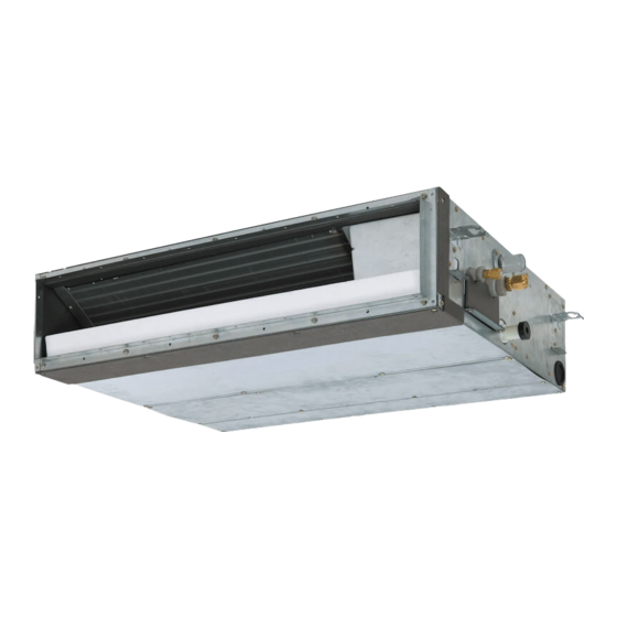
SERVICE MANUAL
AIR-CONDITIONER
INDOOR UNIT
< Slim duct type>
MMD-UP0031SPHY-E
MMD-UP0051SPHY-E
MMD-UP0071SPHY-E
MMD-UP0091SPHY-E
MMD-UP0121SPHY-E
MMD-UP0151SPHY-E
MMD-UP0181SPHY-E
MMD-UP0241SPHY-E
MMD-UP0271SPHY-E
MULTI TYPE
MMD-UP0031SPHY-TR
MMD-UP0051SPHY-TR
MMD-UP0071SPHY-TR
MMD-UP0091SPHY-TR
MMD-UP0121SPHY-TR
MMD-UP0151SPHY-TR
MMD-UP0181SPHY-TR
MMD-UP0241SPHY-TR
MMD-UP0271SPHY-TR
FILE NO. A10-2006
Advertisement
Table of Contents
Troubleshooting

Subscribe to Our Youtube Channel
Related Manuals for Toshiba MMD-UP0031SPHY-E


Summary of Contents for Toshiba MMD-UP0031SPHY-E
- Page 1 FILE NO. A10-2006 SERVICE MANUAL AIR-CONDITIONER MULTI TYPE INDOOR UNIT < Slim duct type> MMD-UP0031SPHY-E MMD-UP0031SPHY-TR MMD-UP0051SPHY-E MMD-UP0051SPHY-TR MMD-UP0071SPHY-E MMD-UP0071SPHY-TR MMD-UP0091SPHY-E MMD-UP0091SPHY-TR MMD-UP0121SPHY-E MMD-UP0121SPHY-TR MMD-UP0151SPHY-E MMD-UP0151SPHY-TR MMD-UP0181SPHY-E MMD-UP0181SPHY-TR MMD-UP0241SPHY-E MMD-UP0241SPHY-TR MMD-UP0271SPHY-E MMD-UP0271SPHY-TR...
-
Page 2: Table Of Contents
CONTENTS PRECAUTIONS FOR SAFETY................. 6 1. SPECIFICATIONS ....................11 2. FAN CHARACTERISTICS..................13 3. CONSTRUCTION VIEWS (EXTERNAL VIEWS)............15 4. WIRING DIAGRAMS....................16 5. PARTS RATING......................17 6. REFRIGERATION CYCLE DIAGRAM ..............18 7. CONTROL OUTLINE ....................19 7-1. Control Specifications ......................19 8. COMMUNICATION TYPE, MODEL NAMES AND THE MAXIMUM NUMBER OF CONNECTABLE UNITS ..................29 9. - Page 3 • The qualified service person is a person who installs, repairs, maintains, relocates and removes the air conditioners made by Toshiba Carrier Corporation. He or she has been trained to install, repair, maintain, relocate and remove the air conditioners made by Toshiba Carrier Corporation...
- Page 4 Definition of Protective Gear When the air conditioner is to be transported, installed, maintained, repaired or removed, wear protective gloves and ‘safety’ work clothing. In addition to such normal protective gear, wear the protective gear described below when undertaking the special work detailed in the table below.
- Page 5 Warning Indications on the Air Conditioner Unit [Confirmation of warning label on the main unit] Confirm that labels are indicated on the specified positions If removing the label during parts replace, stick it as the original. WARNING WARNING ELECTRICAL SHOCK HAZARD ELECTRICAL SHOCK HAZARD Disconnect all remote Disconnect all remote electric power supplies before servicing.
-
Page 6: Precautions For Safety
PRECAUTIONS FOR SAFETY The manufacturer shall not assume any liability for the damage caused by not observing the description of this manual. DANGER Before carrying out the installation, maintenance, repair or removal work, be sure to set the circuit breaker for both the indoor and outdoor units to the OFF position. Otherwise, electric shocks may result. - Page 7 WARNIG Before starting to repair the air conditioner, read carefully through the Service Manual, and repair the air conditioner by following its instructions. Only qualified service person (*1) is allowed to repair the air conditioner. Repair of the air conditioner by unqualified person may give rise to a fire, electric shocks, injury, water leaks and / or other problems.
- Page 8 Do not modify the products.Do not also disassemble or modify the parts. It may cause a fire, electric shock or injury. Prohibition of modification. When any of the electrical parts are to be replaced, ensure that the replacement parts satisfy the specifications given in the Service Manual (or use the parts contained on the parts list in the Service Manual).
- Page 9 After repair work, surely assemble the disassembled parts, and connect and lead the removed wires as before. Perform the work so that the cabinet or panel does not catch the inner wires. If incorrect assembly or incorrect wire connection was done, a disaster such as a leak or fire is caused Assembly / at user’s side.
- Page 10 When the service panel of the outdoor unit is to be opened in order for the compressor or the area around this part to be repaired immediately after the air conditioner has been shut down, set the circuit breaker to the OFF position, and then wait at least 10 minutes before opening the service panel. If you fail to heed this warning, you will run the risk of burning yourself because the compressor pipes and other parts will be very hot to the touch.
-
Page 11: Specifications
1. SPECIFICATIONS MODEL MMD-UP***1SPHY-E/TR NAME Cooling/Heating Capacity (*1) 0.9/1.0 1.7/1.9 2.2/2.5 2.8/3.2 3.6/4.0 4.5/5.0 5.6/6.3 7.1/8.0 8.0/9.0 Power supply 1 phase 220-240V ~ 50Hzz208-230V ~ 60Hz Running 0.34 / 0.36 / 0.40 / 0.42 / 0.44 / 0.47 / 0.53 / 0.69 / 0.74 / current... - Page 12 MODEL MMD-UP***1SPHY-E/TR NAME High Mid.+ Under air Mid. inlet Low+ Sound pressure level <Factory High setting> Mid.+ Back air Mid. inlet Low+ High Mid.+ Sound power level Mid. <Factory setting> Low+ High Mid.+ Under air Mid. inlet Sound Low+ pressure level <Standard external High...
-
Page 13: Fan Characteristics
2. FAN CHARACTERISTICS 003 type 005 type Upper limit of external Upper limit of external static pressure (50Pa) static pressure (50Pa) High (50Pa) High (50Pa) Lower limit of Lower limit of external static external static pressure (50Pa) Low (50Pa) Low (50Pa) pressure (50Pa) High (40Pa) High (40Pa) - Page 14 015 type 018 type Upper limit of external Upper limit of external static pressure (50Pa) static pressure (50Pa) High (50Pa) High (50Pa) Lower limit of external static Lower limit of pressure (50Pa) external static pressure (50Pa) Low (50Pa) Low (50Pa) High (40Pa) High (40Pa) Low (40Pa)
-
Page 15: Construction Views (External Views)
3. CONSTRUCTION VIEWS (EXTERNAL VIEWS) -
Page 16: Wiring Diagrams
4. WIRING DIAGRAMS 超薄型暗藏天花风管式室内机接线图 无出水 机型 泵 无出水泵 (MHY 机型 机型 (MHY CN504 3~ (MCC-1431) 机型 ) (WHI) 适配器电路板 CN81 CN02 (BLK) CN210 (GRN) 2 CN01 (WHI) CN504 CN34 CN34 CN82 (BLU) T6.3A (WHI) (RED) (RED) SW501 (RED) 250V 室内机电控 接地螺钉... -
Page 17: Parts Rating
5. PARTS RATING Model MMD-UP***1SPHY* Fan motor ICF-340WD50-1 ICF-340WD94-3 Drain pump motor MDP-1401 Float switch FS-1A-31 Pulse motor valve PAM-B25YGTF-1 PAM-B40YGTF-1 P.C. board MCC-1643 TA sensor Lead wire length : 328mm Vinyl tube TC1 sensor Dia.4 size lead wire length : 1200mm Vinyl tube (Blue) TC2 sensor Dia.6 size lead wire length : 1000mm Vinyl tube (Black) TCJ sensor... -
Page 18: Refrigeration Cycle Diagram
6. REFRIGERATION CYCLE DIAGRAM Indoor unit Liquid side Gas side Strainer Capillary tubes Heat exchanger at indoor side Pulse Motor Valve (PMV) Strainer Sensor (TCJ) Sensor (TC2) Sensor (TC1) Sensor Fan motor (TA) Explanation of functional parts in indoor unit Functional part name Functional outline Pulse Motor Valve... -
Page 19: Control Outline
7. CONTROL OUTLINE 7-1. Control Specifications Item Outline of specifications Remarks When power 1) Distinction of outdoor unit supply is reset When the power supply is reset, the outdoors are distinguished and the control is selected according to the distinguished result. 2) Setting of indoor fan speed and existence of air direction adjustment Based on EEPROM data, select setting of the indoor fan... - Page 20 Item Outline of specifications Remarks Room temp. 2) By setting the CODE N . 06, the setup temperature in Suction air temperature control heating operation can be compensated. shift of heating operation (Continued) Setup data Setup temp. compensation +0°C +2°C +4°C +6°C Except while sensor of...
- Page 21 Item Outline of specifications Remarks Fan speed Operation with (HH), (H+), (H), (L+), (L) or [AUTO] > H+ > H > L+ > L > UL selection Depends on fan speed mode mode is carried out by the command from the remote selection at the remote controller.
- Page 22 Item Outline of specifications Remarks Fan speed selection Setting of external static pressure mode at code no. (Continued): [5D] or at SW501 on P.C. board. MMD-UP0031SPHY-E/TR, MMD-UP0051SPHY-E/TR Factory default Type1 Type3 Type4 Type6 CODE No. [5d] 0000 0001 0003 0004...
- Page 23 Item Outline of specifications Remarks Fan speed selection Setting of external static pressure mode at code no. (Continued): [5D] or at SW501 on P.C. board. MMD-UP0151SPHY-E/TR, MMD-UP0181SPHY-E/TR Factory default Type1 Type3 Type4 Type6 CODE No. [5d] 0000 0001 0003 0004 0006 SW501 OFF-OFF...
- Page 24 Item Outline of specifications Remarks Prevention of cold air In heating operation, the lowest temperature TCJ: Temperature of indoor discharge between TC1 sensor and the highest heat exchanger sensor temperature between TC2 and TCJ sensor is • In D and E zones, priority set as the upper bound of the fan speed mode is given to remote control- control.
- Page 25 Item Outline of specifications Remarks Freeze prevention 1. In all cooling operation, the air conditioner operates TC1: Temperature of indoor control (Low temp. as described below based upon temp. detected by heat exchanger sensor release) TC1, TC2 and TCJ sensors. •...
- Page 26 Item Outline of specifications Remarks Compensation 1) For 3 minutes after start of operation, the opera- Usually the priority is given to control for short tion is forcedly continued even if the unit enters in 5 minutes at outdoor controller intermittent thermostat.
- Page 27 Item Outline of specifications Remarks < READY> Displayed on the remote controller • < READY> Display of display [READY] 1) When the following check codes are indicated No display for wireless [HEAT READY] type remote controller • Open phase of power supply wiring [P05] was detected. •...
- Page 28 Item Outline of specifications Remarks DC motor Power saving (In the case of RBC-AMT *** ) SAVE mode Push the button on the remote controller The “ ” segment lights up on the wired remote controller display. The requirement capacity ratio is limited to approximately 75 %.
-
Page 29: Communication Type, Model Names And The Maximum Number Of Connectable Units
TCB-TC Remote sensor This letter indicates U series model. Remote sensor... -
Page 30: Applied Control And Functions
9. APPLIED CONTROL AND FUNCTIONS 9-1. Indoor Controller Block Diagram 1. Connection of wired remote controller Wired (Simple) header remote controller (Up to 2 units) Indoor unit #1 (Header) (Follower) (Follower) Indoor control P.C. board (MCC-1643) DC20V Remote controller communication circuit EEPROM DC5V TA sensor... - Page 31 2. Connection of wireless remote controller kit Indoor unit #1 (Header) Wireless remote (Follower) (Follower) controller kit Indoor control P.C. board Receiving (MCC-1643) P.C. board DC20V Remote controller Remote controller communication circuit communication circuit Emergent Power operation EEPROM circuit DC5V DC5V TA sensor DC12V...
- Page 32 3. Connection of both wired remote controller and wireless remote controller kit Wired (Simple) header remote controller Indoor unit #1 (Header) Wireless remote (Follower) (Follower) controller kit Indoor control P.C. board Receiving (MCC-1643) P.C. board DC20V Remote controller Remote controller communication circuit communication circuit Emergent...
-
Page 33: Indoor P.c. Board
9-2. Indoor P.C. board MCC-1643 – 35 –... -
Page 35: Functions At Test Run
9-3. Functions at test run Cooling/Heating test run check ■ The test run for cooling/heating can be performed from either indoor remote controller or outdoor interface P.C. board. Refer to the Installation Manual and Service Manual of outdoor unit for the procedure of the test run from an outdoor interface P.C. - Page 37 Check function for operation of indoor unit (Functions at indoor unit side) ■ This function is provided to check the operation of the indoor unit individually without connecting to the remote controller or the outdoor unit. This function can be used regardless of the ON/OFF operation. However, it is recommend to avoid using this function for along time, otherwise the trouble of the equipment may occurred.
-
Page 38: Setup Of Selecting Function In Indoor Unit
9-4. Setup of Selecting Function in Indoor Unit (Be Sure to Execute Setup by a Wired Remote Controller) <Procedure> Execute the setup operation while the unit stops. SET DATA [MENU] [TIME] [▼] [▲] [ON/OFF] CODE No. [MENU] [TIME] [▼] [▲] [ON/OFF] In STOP status push [MENU] and [▼] buttons simultaneously for at least 10 seconds. - Page 39 code Normal open code Indoor unit Indoor unit TA sensor...
- Page 40 0000: Standard Set data 0000 0001 0003 0004 0006 10Pa External static (Factory 20Pa 30Pa 40Pa 50Pa pressure setting) The list abpve is when SW501-1 and SW501-2 is OFF. Notice code 0001 ~ 0255: 0129: Notice code (201) Notice code 0130: Notice code (202) (0001 ~ 0255: TU2C-LINK only) Notice code...
- Page 41 TYPE Setup data Type Abbreviated Model name 0015 Slim duct type MMD-UP***1SPHY* Indoor unit capacity CODE No. [11] 0044 003 type 0041 005 type 0001 007 type 0003 009 type 0005 012 type 0007 015 type 0009 018 type 0011 024 type 0012 027 type...
-
Page 42: Applied Control In Indoor Unit
9-5. Applied Control in Indoor Unit Remote location ON/OFF control box (TCB-IFCB-4E2) ■ [Wiring and setup] In the case of group control, the control system functions as long as it is connected to one of the indoor units (control P.C. board) in the group. If it is desired to access the operation and trouble statuses of other units, relevant signals must be brought to it from those units individually. - Page 43 ■ Ventilating fan control from remote controller [Function] • The start/stop operation can be operated from the wired remote controller when air to air heat exchanger or ventilating fan is installed in the system. • The fan can be operated even if the indoor unit is not operating. •...
- Page 44 Auto-off feature control [Function] • This function controls the indoor units individually. It is used when the start operation from outside is unnecessary but the stop operation is necessary. • A card switch box or card lock helps protect customers from forgetting to turn off the indoor unit. (not including the following Card Input 3) •...
- Page 45 1) To change a setting temperature by changing data at 1) To change a setting temperature, fan speed and wind DN code No. 172 to 174. direction by changing data at DN code No. 16C to 171. 2) The operation mode can be set by changing data 2) The operation mode can be set by changing data (0000, 0001, 0002) at DN code No.
- Page 46 - The operation mode continues running - The operation mode continues running at the same as the current mode. at the same as the current mode. - The setting temperature of cooling/dry - the setting temperature of cooling/dry and heating mode is changed to 24°C and heating mode is changed to 27°C and 24°C respectively due to change and 20°C respectively due to change...
- Page 47 FILE NO. SVM13011- ■ Address setup (Manual setting from remote controller) In case that addresses of the indoor units will be determined prior to piping work after cabling work (Example of -2lines cabling) (Real line: Cabling, Broken line: Refrigerant pipe) •...
- Page 48 FILE NO. SVM13011- ■ Confirmation of indoor unit No. position • (Follow to the procedure during operation) When the indoor unit is stopped, push [MENU] and [▼] buttons simultaneously for at least 10 seconds. • After entering, the screen displays and the indoor unit number.
- Page 49 FILE NO. SVM13011- Changing the indoor unit address using a remote controller To change an indoor unit address using a wired remote controller. The method to change the address of an individual indoor unit (the indoor unit is paired with a wired remote controller one-to-one), or an indoor unit in a group. (The method is available when the addresses have already been set automatically.) [MENU] [TIME] [▼] [▲] [ON/OFF] (Perform this operation when the air conditioner is stopped)
- Page 50 FILE NO. SVM13011- ■ Check code clearing function 1. Clearing method from remote controller Clearing a check code of the outdoor unit Clear the currently detected outdoor unit for each refrigerant line to which the indoor unit controlled by the remote controller is connected. (The indoor unit check code is not cleared.) Use the service monitoring function of the remote controller.
- Page 51 FILE NO. SVM13011- ■ Monitoring function of remote controller switch When using the remote controller (Model Name: RBC-ASCU11*), the following monitoring function can be utilized. Calling of display <Contents> The temperature of each sensor of the remote controller, indoor unit and outdoor unit and the operating status can be checked by calling the service monitor mode from the remote controller.
- Page 52 Indoor service monitor list Code No. Data name Display format Unit Remote controller display example Room temperature (Use to control) ×1 °C Room temperature (Remote controller) ×1 °C Indoor suction air temperature (TA) ×1 °C Indoor coil temperature (TCJ) ×1 °C Indoor coil temperature (TC2) ×1...
- Page 53 LED display on P.C. board ■ 1. D501 (Red) • D501 goes on at the same time when the power supply is turned on. (Goes on with operation of the main microprocessor) • D501 flashes with 1-second interval (every 0.5 second) : When there is no EEPROM or write-in trouble •...
-
Page 54: Troubleshooting
10. TROUBLESHOOTING 10-1. Overview (1) Before engaging in troubleshooting (a) Applicable models All Super Modular Multi System (SMMS- ) models. (Indoor units: MM -UP , Outdoor units: MMY-M P (b) Tools and measuring devices required • Screwdrivers (Philips, flat head), spanners, long-nose pliers, nipper, pin to push reset switch, etc. •... -
Page 55: Troubleshooting Method
10-2. Troubleshooting method The remote controllers (main remote controller and central control device) and the interface P.C. board of an outdoor unit are provided with an a 7-segment display (outdoor interface P.C. board) to display operational status. Using this self-diagnosis feature, the trouble site / trouble part may be identified in the event of a trouble by following the method described below. - Page 56 (Check code detected by remote controller) Check code Display of receiving unit Outdoor 7-segment display Indicator light block Typical trouble site Description of trouble Remote control Operation Timer Ready Sub-code Flash No master remote control, Signals cannot be received from indoor unit; –...
- Page 57 List of Check Codes (Outdoor Unit) (Check code detected by outdoor interface - typical examples) If "HELLO" is displayed on the oudoor 7-segment for 1 minute or more, turn off the power supply once and then turn on the power supply again after passage of 30 seconds or more. When the same symptom appears, it is considered there is a possibility of I/F board trouble.
- Page 58 Check code Display of receiving unit Outdoor 7-segment display Central Indicator light block Typical problem site Description of problem control or main remote Operation Timer Ready Sub-code controller Flash display Outdoor suction 01: TS1 sensor Outdoor suction temperature sensor temperature sensor 03: TS3 sensor (TS1,TS3) has been open/short-circuited.
- Page 59 Check code Display of receiving unit Outdoor 7-segment display Indicator light block Central Typical problem site Description of problem control or main remote Operation Timer Ready Sub-code Flash controller display P.C.board P.C.board Compressor Fan Motor Compressor Fan Motor Trouble in number of There are insufficient number of P.C.
- Page 60 (Check code detected by Inverter of Compressor featuring in outdoor unit - typical examples) Check code Display of receiving unit Outdoor 7-segment display Central Indicator light block Typical problem site Description of proplem control or main remote Operation Timer Ready Sub-code controller Flash...
-
Page 61: Troubleshooting Based On Information Displayed On Remote Controller
10-3. Troubleshooting based on information displayed on remote controller <RBC-AMT > (1) Checking and testing When a trouble occurs to an air conditioner, a check code and indoor unit No. are displayed on the display window of the remote controller. Check codes are only displayed while the air conditioner is in operation. - Page 62 <RBC-ASCU11- > (1) Confirmation and check If a problem occurs with the air conditioner, the OFF timer indicator alternately shows the check code and the indoor Unit No. in which the problem occurred. Check code The indoor Unit No. in which the problem occurred.
- Page 63 Using indoor unit indicators (receiving unit light block) (wireless type) To identify the check code, check the 7-segment display on the header unit. To check for check codes not displayed on the 7-segment display, consult the “List of Check Codes (Indoor Unit)” in “10-2. Troubleshooting method”. : Blinking (0.5 seconds) : Lighting : Goes off...
- Page 64 Cause of trouble Light block Check code Heat exchanger temperature sensor (TCJ) trouble Operation Timer Ready Heat exchanger temperature sensor (TC2) trouble Indoor unit temperature Heat exchanger temperature sensor (TC1) trouble sensor trouble Ambient temperature sensor (TA) trouble Alternate blinking Discharge temperature sensor (TF) trouble Discharge temperature sensor (TD1) trouble Discharge Operation Timer...
- Page 65 Cause of trouble Light block Check code Operation Timer Ready Occupancy sensor trouble Outdoor EEPROM trouble Synchronized blinking Other (indications not involving check code) Cause of trouble Light block Check code Operation Timer Ready – Test run in progress Synchronized blinking Operation Timer Ready Setting incompatibility...
-
Page 66: Check Codes Displayed On Remote Controller And Smms Series Outdoor Unit
10-4. Check Codes Displayed on Remote Controller and SMMS series Outdoor Unit (7-Segment Display on I/F Board) and Locations to Be Checked For other types of outdoor units, refer to their own service manuals. Check code Location Check code detection Main Outdoor 7-segment display Description... - Page 67 Check code Location Check code detection Main Outdoor 7-segment display Description System status Check items (locations) condition(s) remote Check detection Sub-code controller code No. of indoor Indoor unit Indoor-outdoor All stop Condition 1 • Check power supply to units from indoor unit.
- Page 68 Check code Location Check code detection Main Outdoor 7-segment display Description System status Check items (locations) condition(s) remote Check detection Sub-code controller code Too many All stop • Combined capacity of • Check capacities of indoor Capacity over indoor units indoor units is too large.
- Page 69 Check code Location Check code detection Main Outdoor 7-segment display Description System status Check items (locations) condition(s) remote Check detection Sub-code controller code Detected Outdoor All stop Outdoor header unit • Check check code check outdoor unit No. follower unit receives trouble code from displayed on outdoor code...
- Page 70 Check code Location Check code detection Main Outdoor 7-segment display Description System status Check items (locations) condition(s) remote Check detection Sub-code controller code TD2 sensor y t i • Check connection of TD2 trouble or zero (open/short circuit). sensor connector. •...
- Page 71 Check code Location Check code detection Main Outdoor 7-segment display Description System status Check items (locations) condition(s) remote Check detection Sub-code controller code • Check connection of high- Outdoor pressure Pd sensor and low-pressure pressure Pd sensor sensor wiring Ps sensor are switched. connector.
- Page 72 Check code Location Check code detection Main Outdoor 7-segment display Description System status Check items (locations) condition(s) remote Check detection Sub-code controller code TD1 sensor • Check installation of TD1 miswiring compressor 1 (TD1) does sensor. (incomplete not increase despite •...
- Page 73 Check code Location Check code detection Main Outdoor 7-segment display Description System status Check items (locations) condition(s) remote Check detection Sub-code controller code 01: TK1 oil Oil level All stop No temperature change is • Check for disconnection of circuit trouble detection detected by TK1 despite TK1 sensor.
- Page 74 Check code Location Check code detection Main Outdoor 7-segment display Description System status Check items (locations) condition(s) remote Check detection Sub-code controller code Outdoor • Check model setting of — capacity not set board has not been P.C. board for servicing implemented.
- Page 75 Check code Location Check code detection Main Outdoor 7-segment display Description System status Check items (locations) condition(s) remote Check detection Sub-code controller code 1 : Compressor Activation of All stop High-pressure SW is • Check connection of high- 1 side high-pressure activated.
- Page 76 Check code Location Check code detection Main Outdoor 7-segment display Description System status Check items (locations) condition(s) remote Check detection Sub-code controller code Detected indoor Indoor unit Indoor overflow All stop • Float switch operates. • Check float switch address trouble •...
- Page 77 Check code Location Check code detection Main Outdoor 7-segment display Description System status Check items (locations) condition(s) remote Check detection Sub-code controller code Discharge • Check outdoor service temperature (TD2) exceeds 115 ˚C. valves (gas side, liquid TD2 trouble side) to confirm full opening.
- Page 78 Check code Location Check code detection Main Outdoor 7-segment display Description System status Check items (locations) condition(s) remote Check detection Sub-code controller code 1∗: Fan P.C. Fan INV. Outdoor fan All stop Protected operation of Fan • Check fan motor. board 1 P.C.
- Page 79 Check codes Detected by Central Control Device Check code Location Check code detection Main Outdoor 7-segment display Description System status Check items (locations) condition(s) remote Check detection Sub-code controller code Central Central control Continued Central control device is • Check for failure in central control device.
- Page 80 Points to Note When Servicing Compressor (1) When checking the outputs of inverters, remove the wiring from all the compressors. How to Check Inverter Output (1) Turn off the power supply. (2) Remove compressor leads from the compressor P.C. board. (The model with two compressor should remove the wiring for two sets (6 leads).
-
Page 81: Diagnostic Procedure For Each Check Code (Indoor Unit)
10-5. Diagnostic Procedure for Each Check Code (Indoor Unit) – 118 –... - Page 82 – 119 –...
- Page 83 – 120 –...
- Page 84 – 121 –...
- Page 85 – 122 –...
- Page 86 – 123 –...
- Page 87 – 124 –...
- Page 88 – 125 –...
-
Page 89: Sensor Charateristics
10-6. Sensor charateristics Indoor unit Temperature sensor characteristics Indoor TA sensor Temperature [˚C] Resistance [k Ω ] 33.9 Resistance 26.1 [k Ω ] 20.3 15.9 12.6 10.0 Temperature [˚C] Temperature [˚C] Resistance [k Ω ] –20 99.9 –15 74.1 Indoor TC1 sensor –10 55.6 –5... - Page 90 FILE NO. SVM-13050 Precision metering valve (PMV) coil characteristics Measured parts Resistance values (at 20°C) 180 ~ 220 Ω Red - White 180 ~ 220 Ω Red - Yellow 180 ~ 220 Ω Red - Orange 180 ~ 220 Ω Red - Blue <Maintenance/Check list>...
-
Page 91: Replacement Of Service P.c. Board
11. REPLACEMENT OF SERVICE P.C. BOARD CAUTION <Model name: MMD-UP***1SPHY*> <Note: when replacing the P.C. board for indoor unit servicing> The nonvolatile memory (hereafter called EEPROM, IC503) on the indoor unit P .C. board before replacement includes the model specific type information and capacity codes as the factory-set value and the important setting data which have been automatically or manually set when the indoor unit is installed, such as system/ indoor/group addresses, high ceiling select setting, etc. - Page 92 [1] Setting data read out from EEPROM The setting data modified on the site, other than factory-set value, stored in the EEPROM shall be read out.
- Page 93 CODE No. required at least 1. The Code No. for the Indoor unit type and Indoor unit capacity Contents are required to set the rotation number setting of the fan. Type 2. If the system/indoor/group addresses are different from those Indoor unit capacity before replacement, the auto-address setting mode starts and the manual resetting may be required again.
- Page 94 ing to either methods 1 or 2 shown below. b) Turn on power of the indoor units and proceed to [3]. 1. Turn on only the indoor unit with its P.C. board replaced. (Be sure to confirm the remote controller is ∗...
- Page 96 Table 1. Setting data (CODE No. table (example)) Item Factory-set value Filter sign lighting time Depending on Type Filter pollution level 0000: standard Central control address 00Un/0099: Unfixed Heating suction temperature shift Depending on model type Cooling only 0000: Heat pump Type Depending on model type Indoor unit capacity...
-
Page 97: Detachments
12. DETACHMENTS WARNING CAUTION Be sure to stop operation of the air conditioner Be sure to put on gloves during working time; before work and then turn off switch of the breaker. otherwise an injury will be caused by a part etc. Part name Procedure Remarks... - Page 98 Part name Procedure Remarks ③ Terminal cover 1. Detachment Terminal cover Screw 1) Slightly loosen the screw holding the terminal cover in place. (M4×10 1 pcs) 2) Lifting the terminal cover upward, pull the right side of the cover toward you and then Slit disengage the claws on the left side of the cover from their slits to detach the terminal...
- Page 99 Part name Procedure Remarks ④ Electric parts 1. Detachment Electric parts box cove box cover 1) Perform step 1 of “③Terminal cover” as required. (You may be able to perform this procedure Screws without removing the electric parts box cover.) 2) Slightly loosen the screw holding the electric parts box cover in place.
- Page 100 Part name Procedure Remarks ⑤ Electric parts 1. Detachment Electric parts box 1) For the back air intake, perform the procedure Binding band in 1 of “②Suction panel.” 2) Perform the procedure in 1 of “④Electric parts box cover.” Screws 3) Remove the binding bands and clamps inside Screw the electric parts box.
- Page 101 Part name Procedure Remarks ⑥ Control P.C. 1. Detachment Control P.C. board 1) Perform the procedure in 1 of “④Electric parts box cover.” 2) Disconnect the connectors from other components from the control P.C. board. NOTE) Unlock the lock of the housing to disconnect the connectors.
- Page 102 Part name Procedure Remarks ⑦ Fan case 1. Detachment Fan case (upper) (lower), 1) For the back air intake, perform the procedure Fan case (lower) screw Fan case in 1 of “②Suction panel.” Hanging hook (upper) 2) Remove the screw on the rear of the fan case (lower).
- Page 103 Part name Procedure Remarks ⑧ Fan motor, 1. Detachment Multi blade fan 1) For the back air intake, perform the procedure Clamp in 1 of “②Suction panel.” Binding band 2) Perform the procedure in steps 1-1), 1-2), 1-3) of “④Electric parts box cover.” 3) Disconnect the following connector of the control P.C.
- Page 104 Part name Procedure Remarks ⑨ Under panel, 1. Detachment Drain cap Drain pan 1) Take off the drain cap and drain the drain water accumulated in the drain pan. drain hose Screws In case of natural drain model, drain the drain water by taking off hose band and drain hose.
- Page 105 Part name Procedure Remarks ⑩ Drain pump, 1. Detachment Drain pump Float switch Float switch, 1) Perform the procedure in steps 1-1), 1-2), Drain hose 1-3) of “④Electric parts box cover” and 1 of “⑨Under panel, Drain pan.” * For only 2) Disconnect the following connectors and drain pump connected cables from the control P.C.
- Page 106 Part name Procedure Remarks Sensors ⑪ Heat exchanger 1. Detachment 1) Recover refrigerant, and then remove refrigerant pipes at indoor unit side. 2) Perform the procedure in steps 1-1), 1-2), 1-3) of “④Electric parts box cover” and 1 of Binding band “⑨Under panel, Drain pan.”...
-
Page 107: Exploded Views And Parts List
13. EXPLODED VIEWS AND PARTS LIST – 113 –... - Page 108 Q’ty/Set MMD-UP***1SPHY-E/TR Location Part No. Description 43H22003 CASE,FAN,UPPER 43H22004 CASE,FAN,UPPER 43H22005 CASE,FAN,UPPER 43H22006 CASE,FAN,LOWER 43H22007 CASE,FAN,LOWER 43H22008 CASE,FAN,LOWER 43H21004 MOTOR,FAN 43H21011 MOTOR,FAN 43H00021 PLATE,INLET 43H00022 PLATE,INLET 43H00023 PLATE,INLET 43H70001 HOSE,DRAIN 43H44028 REFRIGERATION CYCLE ASSY 43H44029 REFRIGERATION CYCLE ASSY 43H44031 REFRIGERATION CYCLE ASSY 43H44032 REFRIGERATION CYCLE ASSY 43H49003 SOCKET 43H49004 SOCKET...
- Page 109 Q’ty/Set MMD-UP***1SPHY-E/TR Location Part No. Description 43H80030 AIR FILTER 43H80036 AIR FILTER 43H80037 AIR FILTER 43H80038 RAIL,FILTER 43H80039 RAIL,FILTER 43H80040 RAIL,FILTER 43H00024 FLANGE,OUTLET 43H00025 FLANGE,OUTLET 43H00026 FLANGE,OUTLET 43H97007 SCREW 43H97008 SCREW...
- Page 110 Electric Parts TERMINAL,2P HOLDER SENSOR(TA) PC BOARD ASSY MCC-1643 TERMINAL,4P(AC30V1A) SENSOR TA SENSOR TC SENSOR TC SENSOR TC MMD-UP***1SPHY-E/TR Location Part No. Description 43H50009 SENSOR, TC 43H50010 SENSOR, TC 43H50011 SENSOR, TC 43H50012 SENSOR, TA 43H69082 PC BOARD ASSY, MCC-1643 43H63001 HOLDER, SENSOR(TA) 43H60007...
- Page 111 For the amount of charge in this example: The possible amount of leaked refrigerant gas in rooms A, B and C is 10kg. The possible amount of leaked refrigerant gas in rooms D, E and F is 15kg. – 116 – Toshiba...
- Page 112 Toshiba Carrier Air Conditioning (China) Co., Ltd. Toshiba Carrier Air Conditioning (China) Co., Ltd.
Need help?
Do you have a question about the MMD-UP0031SPHY-E and is the answer not in the manual?
Questions and answers