Table of Contents
Advertisement
Quick Links
Advertisement
Table of Contents

Subscribe to Our Youtube Channel
Summary of Contents for Aginova Sentinel RS-485 DO
- Page 1 Sentinel (RS-485) DO Operation Manual...
-
Page 2: Table Of Contents
Chapter 6 Communication Protocol ......................10 Chapter 7 Maintenance ..........................14 7.1 Sensor Cleaning ..........................14 7.2 Inspection on the Damage of Sensor .................... 14 7.3 Preservation of Sensor ........................14 7.4 Replacement of Fluorescent Cap ....................15 Tel:+1 513 204 5837 Web:https://www.aginova.com... -
Page 3: Chapter 1 Specifications
Operating Temperature 0~45℃ (not freeze) Weight 1.4KG Level of Protection IP68/NEMA6P Cable Length Standard: 10 m, the maximum can be extended 100m Note: The specifications of the product are subject to change without prior notice. Tel:+1 513 204 5837 Web:https://www.aginova.com... -
Page 4: Chapter 2 Product Presentation
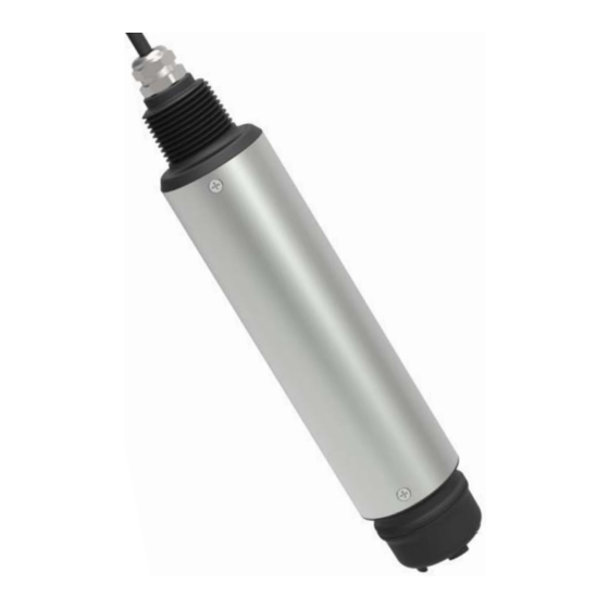
Note: When using the sensor, please pull out the sensor protective cap (Series No.4), Fluorescent cap (Series No.1) is the important part for the measurement function of this sensor. Do not spin down the fluorescent cap (Series No.1). Tel:+1 513 204 5837 Web:https://www.aginova.com... -
Page 5: Chapter 3 Installation
Figure 2 Dimension diagram of Sentinel (RS-485) Dissolved Oxygen Sensor Chapter 3 Installation 3.1 Installation of Sensors Note: The protective cap should be removed before use before measurement. Do not screw down the fluorescent cap. Tel:+1 513 204 5837 Web:https://www.aginova.com... -
Page 6: Quick Dismantling Pool Side Fixed Installation
Sentinel (RS-485) DO • Operation Manual 3.1.1 Quick Dismantling pool side fixed installation Figure 3 Quick Dismantling pool side installation sketch map Tel:+1 513 204 5837 Web:https://www.aginova.com... -
Page 7: Classic Pool Side Fixed Installation
Sentinel (RS-485) DO • Operation Manual 3.1.2 Classic pool side fixed installation Figure 4 Classic pool side fixed installation sketch map Tel:+1 513 204 5837 Web:https://www.aginova.com... -
Page 8: Railing Fixed Installation
Sentinel (RS-485) DO • Operation Manual 3.1.3 Railing fixed installation Figure 5 Railing fixed installation sketch map Tel:+1 513 204 5837 Web:https://www.aginova.com... -
Page 9: Connection Of Sensor
“30” for Quantity in the dialog box , click “OK” Note: After the slave address is changed, the new address will be used for communication and the slave address for the next time connection is also the most recently changed address. Tel:+1 513 204 5837 Web:https://www.aginova.com... -
Page 10: Chapter 5 Calibration Of Sensor
The measured data is stable, Double-click the “06”, and a dialog box pops out. Enter “27” for Address in the dialog box, “16” for Value, then click “Send”. Tel:+1 513 204 5837 Web:https://www.aginova.com... - Page 11 “06”, and a dialog box pops out. Enter “27” for Address in the dialog box, “12” for Value, then click “Send”. Wait 20 seconds, change Value to “19” in the dialog box and click “Send”. Tel:+1 513 204 5837 Web:https://www.aginova.com...
-
Page 12: Chapter 6 Communication Protocol
4800/9600/19200/38400/57600 Data Bits 8 bit Parity Check Stop Bit 1bit Register Name Address Data Type Register Number Read/Write Description Dissolved Oxygen Float R(only read) Value Dissolved Oxygen Float Concentration Temperature Float Range: Slope Float 0.5~1.5 Tel:+1 513 204 5837 Web:https://www.aginova.com... - Page 13 It should be cancelled if you don’t want to calibrate after the execution of “Step 1”. Cancel Signed R:03 Function Code Write 06 as the reshaping data 06 Write 16 as the floating point data 485 analysis: Tel:+1 513 204 5837 Web:https://www.aginova.com...
- Page 14 The equipment return:01 06 00 11 00 0F 99 CB Send command parsing: 01:device address 01 06:Function code 06 for writing register content 00 11:The register address of write data is 0017 00 0F:Write data content of 0015 Tel:+1 513 204 5837 Web:https://www.aginova.com...
- Page 15 The device returns the analysis: 01:device address 01 10:Function code 16 for writing register content 00 06:The starting register address of the return write data is 00 06 00 02:Returns 2 registers A1 C9:CRC16 check code Tel:+1 513 204 5837 Web:https://www.aginova.com...
-
Page 16: Chapter 7 Maintenance
Avoid touching it with hand or other hard objects in case of scratching the fluorescent cap. C、It is forbidden that the fluorescent cap is exposed to direct sunlight or exposure. Tel:+1 513 204 5837 Web:https://www.aginova.com... -
Page 17: Replacement Of Fluorescent Cap
Steps to replace the fluorescent cap: Unscrew the old cap from the sensor, and then screw the new cap on. Note: When removing and installing fluorescent cap, pay attention to whether the sealing ring is out of position. If there is a mismatch, it must be reassembled. version number:R1010_200601 Tel:+1 513 204 5837 Web:https://www.aginova.com...

Need help?
Do you have a question about the Sentinel RS-485 DO and is the answer not in the manual?
Questions and answers