
Related Manuals for compupool products C-CPP Series


Summary of Contents for compupool products C-CPP Series
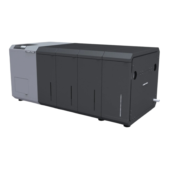
- Page 1 C-CPP Commercial Series Saltwater Chlorine Generator Owner’s Manual Compu Pool C-CPP Commercial Series Manual...
-
Page 2: General Product Specification
GENERAL PRODUCT SPECIFICATION AC Input Power 1.1.1 Single Phase (220-240VAC), Three Phase (208VAC). Agency Approvals 1.2.1 CSA tested to conform to the following UL specifications: UL1081 - Standard for Safety for Swimming Pool Pumps, Filters and Chlorinators. UL1563 - Standard for Safety for Electric Spas, Equipment Assemblies, and Associated Equipment. -
Page 3: Safety Instructions
SAFETY INSTRUCTIONS IMPORTANT SAFETY INSTRUCTIONS, READ AND FOLLOW ALL INSTRUCTIONS. SAVE ALL INSTRUCTIONS. 2.1.1 Follow all aspects of the local and National Electrical Code(s) when installing this device. 2.1.2 NOTE: A bonding terminal is located inside the metal electrical enclosure of this device. -
Page 4: Table Of Contents
C-CPP Commercial Series Saltwater Chlorine Generator Owner’s Manual 1.0 GENERAL PRODUCT SPECIFICATION ........... 2 2.0 SAFETY INSTRUCTIONS ................3 3.0 INTRODUCTION ..................5 4.0 GETTING STARTED .................. 5 5.0 THE CHEMISTRY INVOLVED ..............6 6.0 WATER CHEMISTRY ................. 6 7.0 ADDING SALT TO POOL OR SPA ............9 8.0 INSTALLATION .................. -
Page 5: Introduction
Maintenance personnel should be made familiar with all aspects of the chlorinator. Improper operation or failure to carry out correct maintenance procedures may cause damage to the unit and void the warranty. The C-CPP Series Chlorinator system at a glance. Electronics Electrolytic... -
Page 6: The Chemistry Involved
This form of chlorine works quickly in the pipe, leaving only a mild residual in the pool. WATER CHEMISTRY WARNING: Prior to turning on the C-CPP Series Chlorine Generator for the first time (including reopening the pool for the new pool season) the water chemistry must be balanced according to the following guidelines. - Page 7 6.2.2 Chlorine Stabilizer (Cyanuric Acid). Chlorine Stabilizer is needed to maintain proper levels of chlorine. Unstable chlorine can be destroyed by the sun’s UV radiation within two hours. Chlorine stabilizer must be maintained between 30 – 60 ppm. 6.2.3 Nitrates and Phosphates. These chemicals can cause extremely high chlorine demands and will deplete chlorine from the pool.
- Page 8 Not Recommended List 6.5.1 Do not allow fertilizer anywhere near the pool. Fertilizers contain Nitrates or Phosphates which cause severe chlorine demand in pool water. 6.5.2 Never use dry acid to adjust pH. A build up of by-products can damage the Electrolytic Cell.
-
Page 9: Adding Salt To Pool Or Spa
Salt Level 7.3.1 The Compu Pool C-CPP Series chlorinator can work with a broad salinity range, from a minimum of 3000 ppm (parts per million), up to 6000 ppm. However, the ideal level for operation is 3500 ppm. To achieve this level of salinity, add 30 lbs. of salt for every 1000 gallons of water. -
Page 10: Installation
Positioning 8.1.1 The C-CPP series chlorinator must be installed in a room or area that is protected from the environment and weather. The chlorinator must not be installed into a location that is used for chemical storage as this will void the warranty. - Page 11 Once the plumbing is completed the bypass line valves should be slowly opened to check for proper hydraulic sealing. 8.2.10 The C-CPP Series Chlorinator has been designed to operate with a maximum working pressure of 40Psi (275kPa). Damage to the electrolytic cells may occur if the working pressure exceeds this limit.
- Page 12 01. Remove the two plumbing end 02. Remove the two sheetmetal valve sheetmetal cover panels by unscrewing covers by unscrewing the 8 M4 nuts with the 18 M5 cap head screws with the 4mm a 7mm (9/32") socket. hex key provided. 03.
- Page 13 M2 VALVE M1 VALVE (OUTLET) (INLET) FLOW SENSOR M4 VALVE M5 VALVE M3 VALVE MAIN FLOW RETURN MAIN FLOW RETURN LINE (TO POOL) LINE (FROM FILTRATION) 8.2.12 Figure 1: Plumbing Diagram Compu Pool C-CPP Commercial Series Manual...
- Page 14 Wiring 8.3.1 Before wiring ensure that the single phase and three phase power is turned off at the source. 8.3.2 Power must also be shut off at the Chlorinator circuit breakers before performing any wiring. Be sure to follow local and NEC electrical codes. 02.
- Page 15 8.3.3 The single phase input (220-240VAC) is provided with a three metre cable. This cable is pre-wired to the internal terminals as shown in the following terminal diagram (Figure 2). The Earth wire is connected to the earth terminal that connects to the Earth Stud.
-
Page 16: Installation Checklist
Single Phase Earth Stud ← ← Single Phase Earth In ← Single Phase Active In Single Phase Active to Circuit Breaker ← ← ← Single Phase Neutral In Single Phase Neutral Terminal Internal Fans Active ← Internal Fans Neutral ← External Fan Active ←... -
Page 17: Using The Control Panel
1. On / Off. For normal operation, the system should be left in the “On” position. In this position the Compu Pool C-CPP Series will produce chlorine according to the desired output %. Simply press the button again to turn the unit off. -
Page 18: Maintenance
Chlorine production will only commence when water flow is detected. 10.2.3 Low Salt. The Compu Pool C-CPP Series will automatically let you know if the salinity concentration has fallen below acceptable levels. The warning LED will be illuminated when salt levels fall below 2500ppm. - Page 19 11.2 Electrolytic Cell 11.2.1 The cell operates most efficiently when it is clean. As a natural result of the electrolytic process which creates chlorine from salt molecules, calcium build up is attracted to the titanium plates in the cell. The cell requires regular cleaning to ensure that build up does not cause individual plates to come in contact with each other.
-
Page 20: Warranty
12.0 12.1 Warranty Terms 12.1.1 Compu Pool C-CPP Series chlorine generators carry the following two year warranty should fault occur due to faulty manufacturing or materials. 12.1.2 Compu Pool warrants the original purchaser that the equipment shall be free of... - Page 21 12.1.3 First Year. Parts supplied from our facility or returned for repair to our facility at no cost. Compu Pool reserves the right to determine whether or not a part will be replaced with a new or refurbished part or repaired. 12.1.4 Second Year.
Need help?
Do you have a question about the C-CPP Series and is the answer not in the manual?
Questions and answers