Table of Contents
Advertisement
Quick Links
Advertisement
Table of Contents

Subscribe to Our Youtube Channel
Related Manuals for Specified Controls SC-T32-TS


Summary of Contents for Specified Controls SC-T32-TS
- Page 1 SC-T32-TS Touchscreen Thermostat Installation Manual...
-
Page 3: Table Of Contents
TABLE OF CONTENTS Introduction ............................4 Getting Started ............................5 Installing the Thermostat ........................6-8 Disassembly ..........................6 Thermostat Location ......................6 Mounting the Subbase ......................6-7 Terminal Designations ......................8 Setting the System Switches ........................9 System Switch Functions ........................10 Installing the Batteries ..........................11 Typical System Wiring Diagrams .....................12-20 Heat only (Gas) ........................12 Heat only (Electric)........................13 Cool only (Single or Multi-stage) ...................14... - Page 4 TABLE OF CONTENTS TABLE OF CONTENTS 2 Heat / 1 Cool (Dual Fuel) ....................19 3 Heat / 2 Cool (Dual Fuel) ....................20 Installer Setup Menu ........................21-43 Entering the Setup Menu ......................21 Selecting the Programmable or Non-programmable Operation ..........22 Selecting Number of Program Events ...................23 Selecting Mode ........................24 Selecting Programmable Fan ....................25 Assigning Auxiliary Contacts ....................26...
- Page 5 TABLE OF CONTENTS Timed Ventilation Duration ....................41 Timed Ventilation Low Temp Limit ..................42 Timed Ventilation High Temp Limit ..................43 Daylight Saving Time ......................44 Remote Sensor Installation ......................45-47 Remote Sensor Types ......................45 SC-T-S1 Indoor Sensor Installation .................45-46 SC-T-OTS Outdoor Sensor Installation ................46 Temperature/Resistance Chart ....................47 Display Functions ..........................48 Testing ............................49-53...
-
Page 6: Introduction
INTRODUCTION The SC-T32-TS is a feature-rich touchscreen thermostat that can be battery powered or hardwired to the HVAC equipment. Using a common sense approach to the installation will ensure this product is installed properly and to the customer’s satisfaction. Please take time to read and understand this manual so that installation and testing is performed in an efficient manner. -
Page 7: Getting Started
As with any HVAC project, careful installation is the key to a successful outcome. Time taken during the installation process will be rewarded with fewer call-backs. The steps required to install the SC-T32-TS thermostat are as follows. 1. Read and understand this Installation Manual and User Manual. -
Page 8: Installing The Thermostat
INSTALLING THE THERMOSTAT DISASSEMBLY There are two release slots located on the bottom of the thermostat. Gently push the flat blade of a small screwdriver into one slot at a time and pry upward until the catch disengages. Carefully swing the thermostat upward and away from the subbase. - Page 9 INSTALLING THE THERMOSTAT Pull the control wires through the large opening in the thermostat subbase. Next, level and mount the subbase on the wall using the supplied anchors and screws. (Figure 2) Do not over tighten the mounting screws as the subbase may warp causing the improper seating of the thermostat connecting pins to the terminal blocks.
-
Page 10: Terminal Designations
INSTALLING THE THERMOSTAT TERMINAL DESIGNATIONS TERMINAL DESIGNATION Outdoor Sensor Sensor Common Indoor Sensor Auxiliary Contacts W2/OB Second Stage Heat or Reversing Valve First Stage Cool or First Stage Compressor Second Stage Cool or Second Stage Compressor First Stage Heat/Auxiliary/Emergency Heat 24 VAC Hot 24 VAC Common... -
Page 11: Setting The System Switches
SETTING THE SYSTEM SWITCHES The thermostat contains a set of four system switches located on the thermostat printed circuit board. (Figure 3) The switches are used to match the thermostat operation and relay outputs with the HVAC system requirements. Refer to the system switch functions on the next page to properly configure the thermostat. -
Page 12: System Switch Functions
SYSTEM SWITCH FUNCTIONS Switch 1 - Equipment Type Switch 1 sets the equipment type. For conventional heat/cool equipment, set the switch to the OFF position (factory default). For heat pump equipment set the switch to the ON position. Switch 2 - Fan or When Switch 1 is OFF Reversing Valve For gas heat, set the switch to the OFF position... -
Page 13: Installing The Batteries
INSTALLING THE BATTERIES The thermostat comes with two AA batteries. Even if the thermostat is hardwired, battery backup is recommended to maintain the real-time clock in the event of a power failure. All other memory is non-volatile in the event of battery or primary power loss. -
Page 14: Typical System Wiring Diagrams
TYPICAL SYSTEM WIRING DIAGRAMS HEAT ONLY (GAS) OPTIONAL REMOTE SENSOR TERMINALS THERMOSTAT EQUIPMENT HEAT 1 OUTDOOR INDOOR SENSOR SENSOR RELAY RELAY 24 V LINE Switch Settings Switch 1 = Heat/Cool Switch 2 = Equipment controls fan on call for heat Switch 3 = Single Stage Switch 4 =... -
Page 15: Heat Only (Electric)
TYPICAL SYSTEM WIRING DIAGRAMS HEAT ONLY (ELECTRIC) OPTIONAL REMOTE SENSOR TERMINALS THERMOSTAT EQUIPMENT HEAT 1 OUTDOOR INDOOR SENSOR SENSOR RELAY RELAY 24 V LINE Switch Settings Switch 1 = Heat/Cool Switch 2 = Thermostat controls fan on call for heat Switch 3 = Single Stage Switch 4 =... -
Page 16: Cool Only (Single Or Multi-Stage)
TYPICAL SYSTEM WIRING DIAGRAMS COOL ONLY (SINGLE OR MULI-STAGE) OPTIONAL REMOTE SENSOR TERMINALS THERMOSTAT EQUIPMENT COOL 2 OUTDOOR INDOOR SENSOR SENSOR RELAY COOL 1 RELAY RELAY 24 V LINE Switch Settings Switch 1 = Heat/Cool Switch 2 = Fan energized on call for cooling Switch 3 = OFF/ON = Single Stage... -
Page 17: Heat/1 Cool (Gas)
TYPICAL SYSTEM WIRING DIAGRAMS 1 HEAT/1 COOL (GAS) OPTIONAL REMOTE SENSOR TERMINALS THERMOSTAT EQUIPMENT HEAT 1 OUTDOOR INDOOR SENSOR SENSOR RELAY COOL 1 RELAY RELAY 24 V LINE Switch Settings Switch 1 = Heat/Cool Switch 2 = Fan energized on call for cooling Switch 3 = Single Stage Switch 4 =... -
Page 18: Heat/2 Cool (Gas)
TYPICAL SYSTEM WIRING DIAGRAMS 2 HEAT/2 COOL (GAS) OPTIONAL REMOTE SENSOR TERMINALS THERMOSTAT EQUIPMENT HEAT 2 HEAT 1 COOL 2 OUTDOOR INDOOR RELAY RELAY SENSOR SENSOR RELAY COOL 1 RELAY RELAY 24 V LINE Switch Settings Switch 1 = Heat/Cool Switch 2 = Fan energized on call for cooling Switch 3 =... -
Page 19: Heat/1 Cool (Heat Pump)
TYPICAL SYSTEM WIRING DIAGRAMS 2 HEAT/1 COOL (HEAT PUMP) OPTIONAL REMOTE SENSOR TERMINALS THERMOSTAT EQUIPMENT OUTDOOR INDOOR VALVE RELAY SENSOR SENSOR COMP 1 RELAY RELAY 24 V LINE Switch Settings Switch 1 = Heat Pump Switch 2 = OFF/ON = ‘O’ = ‘B’... -
Page 20: Heat/2 Cool (Heat Pump)
TYPICAL SYSTEM WIRING DIAGRAMS 3 HEAT/2 COOL (HEAT PUMP) OPTIONAL REMOTE SENSOR TERMINALS THERMOSTAT EQUIPMENT COMP 2 OUTDOOR INDOOR VALVE RELAY SENSOR SENSOR RELAY COMP 1 RELAY RELAY 24 V LINE Switch Settings Switch 1 = Heat Pump Switch 2 = OFF/ON = ‘O’... -
Page 21: Heat/1 Cool (Dual Fuel)
TYPICAL SYSTEM WIRING DIAGRAMS 2 HEAT/1 COOL (DUAL FUEL) OPTIONAL REMOTE SENSOR TERMINALS THERMOSTAT EQUIPMENT OUTDOOR INDOOR VALVE RELAY SENSOR SENSOR COMP 1 RELAY RELAY 24 V LINE Switch Settings Switch 1 = Heat Pump Switch 2 = OFF/ON = ‘O’ = ‘B’... -
Page 22: Heat / 2 Cool (Dual Fuel)
TYPICAL SYSTEM WIRING DIAGRAMS 3 HEAT / 2 COOL (DUAL FUEL) OPTIONAL REMOTE SENSOR TERMINALS THERMOSTAT EQUIPMENT COMP 2 OUTDOOR INDOOR VALVE RELAY SENSOR SENSOR RELAY COMP 1 RELAY RELAY 24 V LINE Switch Settings Switch 1 = Heat Pump Switch 2 = OFF/ON = ‘O’... -
Page 23: Installer Setup Menu
INSTALLER SETUP MENU ENTERING THE SETUP MENU Tap the display to bring the back light on then press and hold both the Clock Mode section for 5 seconds to enter the Installer Menu. 01/01/2012 o advance through the menu, touch Next. To back up in the menu, touch Back. -
Page 24: Selecting The Programmable Or Non-Programmable Operation
INSTALLER SETUP MENU SELECTING THE PROGRAMMABLE OR NON-PROGRAMMABLE OPERATION The first menu 01 selects programmable or non-programmable operation. Press the DOWN arrows to change the selection. The factory default is . Back Next Program Morning Day Evening Night 7 = 7-Day Programmable (Factory Default) 0 = Manual Mode (Non-programmable) -
Page 25: Selecting Number Of Program Events
INSTALLER SETUP MENU SELECTING NUMBER OF PROGRAM SCHEDULES ONLY DISPLAYED WHEN 01 = 7 If menu 01 is set to 7, the thermostat can be configured for 4 or 2 schedules per day. The factory default is . 4 Back Next 4 = 4 schedules per day (Factory Default) 2 = 2 schedules per day... -
Page 26: Selecting Mode
INSTALLER SETUP MENU SELECTING MODE Menu 03 selects the mode of operation. The factory default is . 0 Back Next Program 0 = Auto-changeover (Heat/Cool/Auto/Off for Heat/Cool) (Heat/Cool/Auto/EHeat/Off for Heat Pump (Factory Default) 1 = Manual Changeover (Heat/Cool/Off) or (Heat/Cool/E.Heat/Off) 2 = Heating Only (Heat/Off) or (Heat/E.Heat/Off) 3 = Cooling Only (Cool/Off) -
Page 27: Selecting Programmable Fan
INSTALLER SETUP MENU SELECTING PROGRAMMABLE FAN Menu 04 selects the Programmable Fan option which allows selecting continuous or auto fan operation for each program event when programmable mode is selected. The factory default is . 0 Back Next Program 0 = No Programmable Fan (Factory Default) 1 = Programmable Fan Refer to the User Manual for selecting continuous or auto fan for each scheduled event when the Programmable Fan option is ON. -
Page 28: Assigning Auxiliary Contacts
INSTALLER SETUP MENU ASSIGNING AUXILIARY CONTACTS Menu 05 assigns the auxiliary dry relay contacts (AUX) as Normally Open or Normally closed when the Programmable Fan Option 04 is ON. Whenever Programmable Fan is in Always On mode (constant ventilation) for a selected program period, the relay contact will go open or closed based on the auxiliary relay option selection. -
Page 29: Selecting Touchscreen Lock Options
INSTALLER SETUP MENU SELECTING TOUCHSCREEN LOCK OPTIONS Menu 06 allows you to prevent changes to all or part of the touchscreen functions. The factory default is . Touch the DOWN arrows to change the selection. Next Back 0 = All functions unlocked (Factory Default) 1 = All functions locked except setpoint adjustment 2 = All functions locked... -
Page 30: Selecting The Cooling Setpoint Limit
INSTALLER SETUP MENU SELECTING THE COOLING SETPOINT LIMIT Menu 07 selects the minimum cooling setpoint. The factory default is . Touch the DOWN arrows to adjust the limit from 43° - 122°F. Next Back... -
Page 31: Selecting The Heating Setpoint Limit
INSTALLER SETUP MENU SELECTING THE HEATING SETPOINT LIMIT Menu 08 selects the maximum heating setpoint limit. The factory default is . Touch the DOWN arrows to adjust the limit from 41° - 120°F. Heat Next Back... -
Page 32: Selecting Back Light Option
INSTALLER SETUP MENU SELECTING BACK LIGHT OPTION Menu 09 allows you to select the back light option. The factory default is . Touch the DOWN arrows to change the display option. Next Back 0 = Back Light on for 10 seconds when screen is touched 1 = Back Light on high for 10 seconds when screen is touched and then low continuously. -
Page 33: Selecting Adaptive Recovery Option
INSTALLER SETUP MENU SELECTING ADAPTIVE RECOVERY OPTION Menu 10 allows you to select the Adaptive Recovery option. Only displayed when 01 is set to 7. Adaptive Recovery compares the space temperature deviation from setpoint and rate of recovery history to bring the equipment on and reach the setpoint at the scheduled start time. -
Page 34: Selecting First Stage Heating And Cooling Differential Option
INSTALLER SETUP MENU SELECTING FIRST STAGE HEATING AND COOLING DIFFERENTIAL OPTION Menu 11 is used to adjust the heating and cooling differential. The factory default is (1°F). This represents the temperature above the cooling setpoint or below the heating setpoint when the equipment is energized. -
Page 35: Selecting Second Stage Heating And Cooling Differential Option
INSTALLER SETUP MENU SELECTING SECOND STAGE HEATING AND COOLING DIFFERENTIAL OPTION Menu 12 is used to adjust the second stage heating and cooling differential. The factory default is (2°F). This represents the temperature above the first stage cooling differential or below the first stage heating differential when second stage is energized. Touch the DOWN arrows to change the differential. -
Page 36: Selecting Third Stage Heating Differential Option
INSTALLER SETUP MENU SELECTING THIRD STAGE HEATING DIFFERENTIAL OPTION Menu 13 is used to adjust the third stage heating differential. Only displayed when SW1 and SW 3 are ON. The factory default is (2°F). This represents the temperature below the second stage heating differential when third stage heat is energized. Touch the DOWN arrows to change the differential. -
Page 37: Selecting Demand Staging Or Locked Staging Option
INSTALLER SETUP MENU SELECTING DEMAND STAGING OR LOCKED STAGING OPTION Menu 14 is used to select how the thermostat will stage the equipment. The factory default is which = Demand Staging . Demand Staging allows the thermostat to upstage or downstage the equipment based on the stage differential settings. In dual fuel setup, the thermostat will not downstage to compressor if fossil fuel is energized. -
Page 38: Sensor Calibration
INSTALLER SETUP MENU SENSOR CALIBRATION Menu 15 allows you to re-calibrate the internal or a single indoor remote sensor. When a remote sensor is wired to the SC and S1 terminals, the internal sensor is automatically disabled. The factory default is (0°F). -
Page 39: Selecting Low Balance Point Option
INSTALLER SETUP MENU SELECTING LOW BALANCE POINT OPTION Menu 16 allows you to select a low balance point setting when the thermostat is configured for Heat Pump or Dual Fuel and an outdoor sensor is used. When the outdoor temperature falls below the balance point setting, the compressor is locked out and only auxiliary electric heat or dual fuel furnace is used for heating. -
Page 40: Selecting High Balance Point Option
INSTALLER SETUP MENU SELECTING HIGH BALANCE POINT OPTION Menu 17 allows you to select a high balance point setting when the thermostat is configured for Heat Pump or Dual Fuel. When the outdoor temperature rises above the balance point setting, the auxiliary electric heat or dual fuel furnace is locked out and only the heat pump is used for heating. -
Page 41: Selecting Fahrenheit Or Celsius
INSTALLER SETUP MENU SELECTING FAHRENHEIT OR CELSIUS Menu 18 allows you to select temperature readings and temperature setpoints in Fahrenheit or Celsius. The factory default is (Fahrenheit). Touch the DOWN arrows to select (Celsius). Next Back... -
Page 42: Selecting Audible On/Off
INSTALLER SETUP MENU SELECTING AUDIBLE ON/OFF Menu 26 allows you to select an audible beep whenever the screen is touched or to silence the beep. The factory default is audible beep . Touch the DOWN arrows to change the selection. Next Back ON = Audible Beep... -
Page 43: Timed Ventilation Duration
INSTALLER SETUP MENU TIMED VENTILATION DURATION Menu 27 is used to select Timed Ventilation when Menu 05 is set to 3. Timed Ventilation is used to bring outside air into the home at a controlled CFM rate based on ASHRAE 62.2 - 2013 Ventilation and Indoor Air Quality Standard. -
Page 44: Timed Ventilation Low Temp Limit
INSTALLER SETUP MENU TIMED VENTILATION LOW TEMPERATURE LIMIT Menu 28 is used to select a low outdoor temperature when a remote outdoor sensor is installed. If the temperature is lower than or equal to the selected value, Timed Ventilation is suspended. Menu 28 is only displayed if thermostat is fitted with an outdoor sensor. Next Back Range = OFF - 0-50 degrees in 1 degree increments. -
Page 45: Timed Ventilation High Temp Limit
INSTALLER SETUP MENU TIMED VENTILATION HIGH TEMPERATURE LIMIT Menu 29 is used to select a high outdoor temperature limit when a remote outdoor sensor is installed. If the temperature is higher than or equal to the selected value, Timed Ventilation is suspended. Menu 29 is only displayed if thermostat is fitted with an outdoor sensor. -
Page 46: Daylight Saving Time
INSTALLER SETUP MENU DAYLIGHT SAVING TIME Menu 30 is used to enable or disable Daylight Saving Time (DST). In areas of the country where DST is not observed, the feature can be disabled. Touch the DOWN arrows to change the selection. Next Back 1 = DST (Factory Default) -
Page 47: Remote Sensor Installation
REMOTE SENSOR INSTALLATION REMOTE SENSOR TYPES The thermostat can accommodate both an indoor and outdoor remote sensor. For indoor applications, the SC-T-S1 remote sensor can be wired to the thermostat terminals. Each sensor contains two thermistors wired in series with a switch to select one or both sensors. This reduces the total number of sensors required for series/parallel temperature averaging. -
Page 48: Sc-T-Ots Outdoor Sensor Installation
SC-T-OTS OUTDOOR SENSOR INSTALLATION When the SC-T-OTS is wired to the SC-T32-TS, it will display the outside air temperature as well as control high and low balance points for heat pump or dual fuel systems. Refer to the SC-T-OTS installation guide for additional information. -
Page 49: Temperature/Resistance Chart
REMOTE SENSOR INSTALLATION TEMPERATURE/RESISTANCE CHART Temperature Resistance Temperature Resistance (°F) (K ) Ω ( F) º (K ) Ω 34.6 11.9 26.1 19.9 15.3 NTC type 2 sensor - 10K @ 77° F Ω... -
Page 50: Display Functions
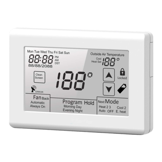
DISPLAY FUNCTIONS DAYLIGHT SAVINGS TIME DISPLAYED WITH OUTSIDE DISPLAYED WHEN DST IS ACTIVE DAYS OF THE WEEK AIR TEMPERATURE AND (DST CAN BE DISABLED) FLASHES WHEN ANY OUTDOOR LIMIT IS EXCEEDED TIME OF DAY (OPTIONAL OUTDOOR SENSOR REQUIRED) 12 HOUR ONLY Mon Tue Wed Thu Fri Sat Sun Outside Air Temperature WITH AM/PM... -
Page 51: Testing
TESTING FAN OPERATION Touch Mode until the word is displayed. Touch FAN until the words Always On appear. After a brief moment, the internal fan relay ‘G’ will energize and the system fan should operate. Touch again until the word Automatic appears. -
Page 52: Conventional Heat Pump
TESTING Note: On a call for cooling, the thermostat activates a 3 minute time delay before the cooling relay ‘Y1’ is energized. Mode will flash to indicate the thermostat is in time delay. After the time delay, the internal fan ‘G’ and cooling relay ‘Y1’ will energize. -
Page 53: Dual Fuel
TESTING DUAL FUEL When the thermostat is configured for dual fuel operation, testing is the same as a heating and cooling system with the exception that a 3 minute time delay is activated before the ‘Y1’ compressor relay will energize on a call for heating or cooling. -
Page 54: High Balance Point
TESTING To test the low balance point setting, set Option 16 above the displayed outdoor temperature and force a call for heating. Only the auxiliary heat relay ‘W1’ should energize. After testing, reset the low balance point setting to a normal operating range. -
Page 55: Programmable Fan
TESTING the designated time. PROGRAMMABLE FAN Programmable Fan (Installer Option 04 = 0) is used to program the fan operation along with the thermostat schedule. This is a very convenient feature that allows selecting continuous (Always ON) or Automatic fan operation for each scheduled event. - Page 56 AUXILIARY CONTACTS The auxiliary dry contacts can be used with the Programmable Fan feature when the Programmable Fan Option 04 is ON. They can also be used for Timed Ventilation when Option 05 is set to 3. Timed Ventilation is designed to improve residential indoor air quality by introducing fresh, outside air through a 2-wire, power open / spring closed motorized intake damper controlled by the thermostat.
-
Page 57: Timed Ventilation Setup
TIMED VENTILATION SETUP The reference chart below provides the ventilation timer setting (Installer Option 27) based on using 8” rigid straight duct with friction loss of 0.1” w.g. per 100 ft. This chart can be used for most applications. VENTILATION TIMER SETTING (MINUTES PER HOUR) THREE FOUR FIVE... -
Page 58: Basic Troubleshooting
BASIC TROUBLESHOOTING SYMPTOM POSSIBLE FAULT AND REMEDY No LCD display If the thermostat is battery powered only, remove the battery compartment and check to see that the positive (+) and negative (-) ends of each battery are oriented properly. Also make sure that the thermostat is securely attached to the subbase with no exposed gaps. - Page 59 BASIC TROUBLESHOOTING SYMPTOM POSSIBLE FAULT AND REMEDY Heat or Cool is flashing This is not a fault but indicates that the thermostat heating or cooling relay is energized. Depending upon the equipment configuration, Heat 2 or Cool 2 will also be displayed if a second stage is energized. Heat 3 is also displayed for heat pumps having three heating stages.
-
Page 60: Specifications
SPECIFICATIONS Input Voltage (Hardwired) 20-30 VAC 50/60 Hz Relay Rating 24 VAC @ 1 Amp maximum per relay Battery Power (2) AA 1.5 V Operating Temperature 32° F to 150° F Operating Relative Humidity 0-95% RH (non-condensing) Storage Temperature 32° F to 150° F Overall Size 5.5”...
Need help?
Do you have a question about the SC-T32-TS and is the answer not in the manual?
Questions and answers