Table of Contents
Advertisement
Quick Links
Advertisement
Table of Contents

Subscribe to Our Youtube Channel
Related Manuals for Specified Controls SC-T32-P


Summary of Contents for Specified Controls SC-T32-P
- Page 1 Installation Manual SC-T32-P Universal Thermostat Version 3.0...
- Page 2 HVAC equipment or seriously affect performance. The SC-T32-P thermostat is intuitive, reliable and easy to install. Using a common sense approach to the installation will ensure this product is installed properly and to the customer’s satisfaction. Please take time to read and understand this manual so that installation and testing is performed in an efficient manner.
-
Page 3: Getting Started
As with any HVAC project, careful installation is the key to a successful outcome. Time taken during the installation process will be rewarded with fewer call-backs. The steps required to install the SC-T32-P thermostat are as follows: 1. Read and understand this Installation Manual and Operation Manual. -
Page 4: Terminal Designations
Diagrams” in the manual). (Figure 2) FIGURE 2 Refer to Typical System Wiring Diagrams in this manual. TERMINAL DESIGNATIONS functions. Based on the SC-T32-P slide switch configurations, some terminals have multiple output (Figure 3) FACTORY JUMPER Power Coms W2 Y2 O/B Y1 G... -
Page 5: Special Instructions For Dual Fuel Applications
SPECIAL INSTRUCTIONS FOR DUAL FUEL APPLICATIONS When the SC-T32-P is used with dual fuel systems, an outdoor sensor is recommended for balance point control (Model SC-T-S1). The sensor is wired to the TT terminals on the thermostat. In the Advanced Installer Settings, set TT = OA. This configures the thermostat to receive the outdoor temperature information. -
Page 6: System Switch Functions
SYSTEM SWITCH FUNCTIONS Sw1 - Equipment Type Switch 1 sets the equipment type. For heat / cool equipment, set the switch to the OFF position (factory default). For heat pump equipment, set the switch to the ON position. Sw2 - Equipment Stages Switch 2 sets the equipment stages. -
Page 7: Typical System Wiring Diagrams
TYPICAL SYSTEM WIRING DIAGRAMS HEAT OR COOL ONLY HEAT 1 FAN 1 MODBUS RELAY RELAY TERMINALS COMP 1 RELAY 24 V LINE Switch Settings Sw1 = OFF (Heat/Cool) Sw2 = OFF (Single Stage) Sw3 = OFF (Not Applicable) Sw4 = OFF (Not Applicable) Sw5 = Equipment Type (OFF = Equipment Controls Fan - Gas) -
Page 8: Heat / 1 Cool Heat Pump
TYPICAL SYSTEM WIRING DIAGRAMS 2 HEAT / 2 COOL HEAT 2 HEAT 1 FAN 1 MODBUS RELAY RELAY RELAY TERMINALS COMP 2 COMP 1 RELAY RELAY LINE 24 V Switch Settings Sw1 = OFF (Heat/Cool) Sw2 = ON (Multi-stage) Sw3 = OFF (Not Applicable) Sw4 = OFF (Not Applicable) -
Page 9: Heat / 2 Cool Heat Pump
TYPICAL SYSTEM WIRING DIAGRAMS 3 HEAT / 2 COOL HEAT PUMP FAN 1 MODBUS HEAT VALVE RELAY TERMINALS COMP 2 COMP 1 RELAY RELAY LINE 24 V Switch Settings Sw1 = ON (Heat Pump) Sw2 = ON (Multi-stage) Sw3 = OFF (Conventional Heat Pump) Sw4 = Reversing Valve (OFF = ‘O’)) -
Page 10: Heat / 2 Cool Dual Fuel
Advanced Installer menu. ENTERING THE ADVANCED INSTALLER SETTINGS MENU The SC-T32-P contains factory defaults for all Advanced Installer Settings. Depending upon the user and equipment application, some settings may need to be changed. To enter the Advanced Installer Settings menu, push the O/RIDE button once, then hold it down (15 seconds) until the LCD displays LC which is the first menu item. - Page 11 ADVANCED INSTALLER SETTINGS MENU Symbol Default Function Maximum Heating Setpoint Limit Adjustable from 41° F - 120° F Minimum Cooling Setpoint Limit Adjustable from 43° F - 122° Temperature Display CF=F - Fahrenheit CF=C - Celsius Internal Sensor Calibration Adjustable +/- 9° F in 0.2° F increments Time Format TC=12 - 12 Hour Time TC=24 - Military Time...
-
Page 12: Tt Terminal Functions
Do not change this function without reading the Factory Test Mode instructions on Page 27 TT TERMINAL FUNCTIONS The ‘T’ and ‘T’ terminals on the SC-T32-P are used for wiring either an indoor or an outdoor remote sensor. Each configuration requires setup in the Advanced Installer menu. -
Page 13: Indoor Sensor Wiring
TT TERMINAL FUNCTIONS INDOOR SENSOR WIRING When the SC-T-S1 is used as an indoor sensor, the SC-T32-P can be configured to allow only the remote sensor to control SC-T-S1 SENSOR the temperature (TT=RS) or both the remote and onboard sensor can be used for temperature averaging (TT=AV). -
Page 14: Testing Fan Operation
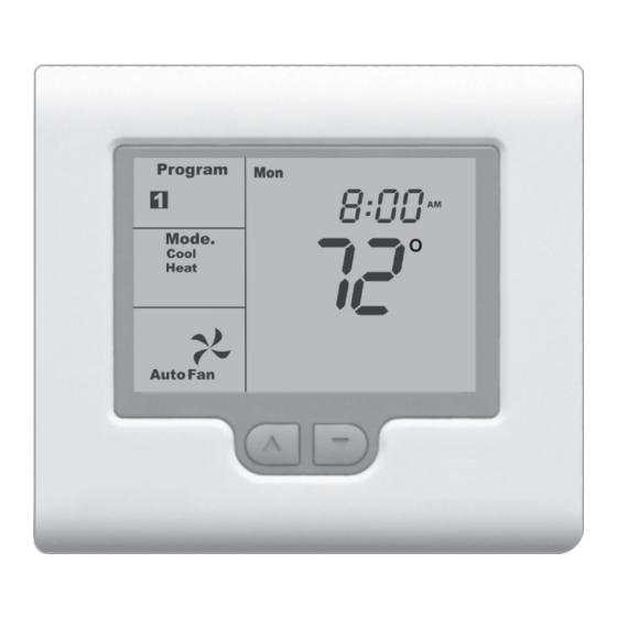
Troubleshooting Guide in this manual if any problems are encountered. When the SC-T32-P is powered, the LCD will briefly show all available LCD icons, software version, then display the time and operating mode, etc. -
Page 15: Adaptive Recovery
Mode. TESTING HEAT PUMP OPERATION When the SC-T32-P is configured for heat pump operation, testing is the same as for a conventional heating and cooling system with the exception that the fan relay is energized on a call for both heating and cooling. -
Page 16: Basic Troubleshooting
The limit values can be changed in the Advanced lower cooling temperature. Installer menu. Thermostat displays wrong The SC-T32-P can display in either Fahrenheit or Celsius. Change temperature CF=C or F in the Advanced Installer menu. The fan continues to run after The thermostat is set to Fan On. -
Page 17: Remote Sensor Installation Instructions
REMOTE SENSOR INSTALLATION INSTRUCTIONS The SC-T32-P can use an indoor remote sensor or multiple sensors for temperature averaging, or as an outdoor sensor for temperature display or a control function depending upon the thermostat configuration. INDOOR SENSOR INSTALLATION Locate the sensor in the same manner as a thermostat. Mount the sensor 18” away from any outside wall. -
Page 18: Specifications
SPECIFICATIONS Input Voltage 24 VAC 50/60 Hz Relay Rating 24 VAC @ 1Amp maximum per relay Operating Temperature 32° F to 122° F Operating Relative Humidity 0-95% (non-condensing) Storage Temperature 32° F to 105° F Size 4-7/16” W x 4-1/16” H x 7/8” D LCD Display Size 2-3/4”...
Need help?
Do you have a question about the SC-T32-P and is the answer not in the manual?
Questions and answers