
Related Manuals for CSF Inox CS Series


Summary of Contents for CSF Inox CS Series
- Page 1 CENTRIFUGAL PUMPS CS Series INSTRUCTIONS FOR INSTALLATION, OPERATION AND MAINTENANCE...
- Page 3 C.S.F. Inox S.p.A. reserves all rights concerning this manual and the object presented herein. The receiving party shall recognize these rights and undertakes, in the absence of our explicit written authorization, not to use this manual for any purpose other than that for which it was created.
-
Page 4: Table Of Contents
Translation of the original instructions INDEX FOREWORD ................................6 1.0 - SYMBOLS .................................6 2.0 - SAFETY WARNINGS ............................6 3.0 - GUARANTEE ..............................7 4.0 - GOODS TRANSPORTATION, RECEIVING AND TRANSFERRING ............7 4.1 - TRANSPORT .............................7 4.2 - RECEIPT ..............................7 4.3 - INSTALLATION SITE PREPARATION .....................7 4.4 - HANDLING ..............................8 5.0 - RETURN ................................ - Page 5 16.0 - PUMP ASSEMBLY ............................34 16.1 - ASSEMBLY OF PUMP "T/W" EXEC.....................34 16.2 - ASSEMBLY OF PUMP "Q" EXEC.......................34 16.3 - REFERENCE TABLE FOR IMPELLER NUT DIMENSIONS .............34 16.4 - REFERENCE TABLE FOR CLAMP TIGHTENING TORQUES ............34 16.5 - REFERENCE TABLE FOR IMPELLER - COVER ASSEMBLY ALLOWANCE ........35 17.0 - BEARINGS MAINTENANCE ........................35 17.1 - SERIES CS BEARINGS MAINTENANCE ...................35 17.2 - SERIES CS - CSX BEARINGS MAINTENANCE WITH HOUSING SIZE 160÷200 ......35...
-
Page 6: Foreword
FOREWORD Read the instructions carefully and keep them for future consultation. C.S.F. Inox S.p.A. reserves the right to make any changes to the documentation it deems necessary without being obliged to update publications that have already been issued. When requesting information, spare parts or assistance, always specify the pump type (2) and serial number (3) in order to ensure fast and efficient service: the complete code is given on the plate and in the purchase documents. -
Page 7: Guarantee
3.0 - GUARANTEE All products manufactured by C.S.F. Inox S.p.A. are guaranteed to the purchaser, for one year from the date of purchase, against hidden defects in materials or manufacture, providing that they are installed and used according to instructions and recommendations of the manufacturer. The guarantee does not cover wear parts or repairs for damage caused by improper use, abrasion, corrosion, negligence, defective installation, non-observance of inspection and maintenance operations, use of non-genuine spare parts, accidents or any work carried out by the purchaser... -
Page 8: Return
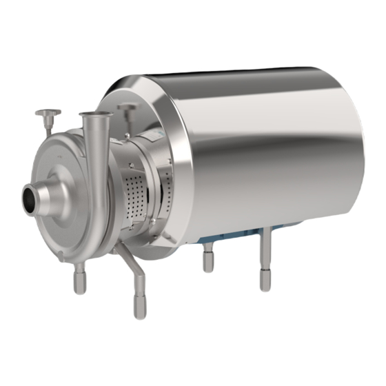
▪ A duly compiled Declaration of Decontamination must accompany the pump (see page 47). 6.0 - DESCRIPTION The CS series comprises single-stage centrifugal pumps with axial suction port, open centrifugal impeller and trapezoidal volute casing. All models have threaded connections for fittings to DIN 11851 standards (unless otherwise requested) and all models are fitted with mechanical seals. -
Page 9: Sound Pressure Level
6.2 - SOUND PRESSURE LEVEL The sound pressure level of centrifugal pumps is the following (see table): PUMP TYPE CS 25-145 4-pole CS 25-175 4-pole CS 32-110 4-pole CS 32-145 4-pole CS 32-175 4-pole CS 32-210 4-pole CS 32-260 4-pole CS 40-145 4-pole CS 40-175... - Page 10 TABLE OF WEIGHTS FOR CS PUMPS - MOTORS FROM 0.37 KW TO 4 KW (IEC 71-112 FRAME SIZE) Weight Weight Weight Pump type Pump type Pump type 0.37 0.55 0.55 CS 25-145 0.55 0.75 0.75 CS 25-145 0.75 CS 50-175 0.37 CS 25-175 0.55...
- Page 11 TABLE OF WEIGHTS FOR CS PUMPS - MOTORS FROM 5.5 KW TO 22 KW (IEC 132-180 FRAME SIZE) Weight Weight Weight Pump type Pump type Pump type CS 65-260 CS 32-210 CS 50-210 CS 80-175 18.5 CS 32-260 CS 80-210 CS 50-260 18.5 CS 80-260...
- Page 12 TABLE OF WEIGHTS FOR CSK EXECUTION PUMP (2 GROUP) Weight Weight Pump type Pump type CSK 32-145 CSK 65-210 CSK 32-175 CSK 65-260 CSK 32-210 CSK 80-175 CSK 40-145 CSK 80-210 CSK 40-175 CSK 80-260 CSK 40-210 CSK 100-210 CSK 50-145 CSK 100-260 CSK 50-175 CSK 100-310...
- Page 13 8.0 - EXECUTIONS CS - shroudless execution with adjustable support CS - shrouded execution with feet from 0.37kW to 4 kW adjustable support feet from 0.37 kW to 4 kW CS - shroudless execution with adjustable CS - shrouded execution with adjustable support feet from 5.5 kW to 22 kW support feet from 5.5 kW to 22 kW CS - shroudless execution with fixed...
-
Page 14: Csk Series Installation
9.0 - CSK SERIES INSTALLATION 9.1 - INSTALLATION ON FOUNDATION PLINTH The foundation plinth must be of the required structure and solidity. It must be prepared based on the dimensions provided in the dimensions sheet/installation diagram. Proceed as follows: Thickness Thickness with (L) >... - Page 15 3. Axial and angular alignment Position the hubs at distance E, as for Table 1. Using the thickness feelers, you can control the gap between hubs, measurement E (keep to axial tolerance X). It is advisable to check the values of measurement E in three positions (O-90-180 degrees), as this will ensure more precise angular alignment (keep to angular alignment Z).
- Page 16 7. Disassembly Remove the two set screws from the ring. Shift the ring by tapping it on the side with a nylon hammer in the areas the pins (reference lines) are housed. PERMITTED SALIGNMENT TOLERANCES Tab. 1 Type A00 A0 A4 A45 A5 A55 A6 A9 A10 A11 Axial X...
-
Page 17: Installation
PERMITTED SALIGNMENT TOLERANCES Tab. 3 Dimension (E) and tolerance in mm. Type A45C A55C Axial X +0.5 +0.5 +0.7 +0.8 +1.0 +1.0 +1.0 +1.0 +1.0 +1.5 Radial Y 0.15 0.20 0.20 0.20 0.20 0.20 0.30 0.30 Angular Z 0.20 0.20 0.30 0.40 0.40... - Page 18 The suction pipe must be as short as possible and rise as it moves towards the pump if it is sucking from a tank (Pict.2). If on the other hand the pump is below the level of the liquid, the pipe should descend slightly (Pict.3).
-
Page 19: Electrical Connection
10.3 - ELECTRICAL CONNECTION Make the electrical connection only after the hydraulic connection has been completed; set up the motor control system in conformity with the technical standards and regulations in force (EN 60204-1): in particular a manual electric power switch must be installed with adequate current switching capacity;... -
Page 20: Operation
11.0 - OPERATION 11.1 - PRELIMINARY OPERATIONS BEFORE START-UP - Check that the pump turns freely under hand pressure - The clamp joining the pump casing and the lantern bracket must be well tightened and it should not be easily unscrewed by hand. The clamp must be tightened using a wrench and NOT simply by hand. -
Page 21: Cleaning The Pump
- The pump must operate smoothly and without vibrations. - Do not operate without liquid and in any case avoid prolonged operation with the discharge gate valve closed. - Check that the suction liquid level is always sufficient to grant an adequate energy load for normal operation of the pump. -
Page 22: Spare Parts
12.0 - SPARE PARTS 12.1 - REFERENCE TABLE OF MAIN PARTS SUBJECT TO REPLACEMENT Pump type CS-CSX 32-110 25-145 25-175 Detail -145 -175 -210 -175 -210 -260 -310 -350 * Mechanical seal D.20 D.28 D.43 D.55 EN12756-ISO3069 Casing O-ring OR 6412 OR 215 OR 6670 OR 215 OR 81300 6670 6795... - Page 23 13.0 - OPERATING MALFUNCTIONS We are herewith listing some of the possible working irregularities which may occur using the pumps, with a table helping to find out the possible causes and how to solve the problem. Trouble: A) The pump does not run F) Leaks from mechanical seal B) The delivery is not sufficient G) Short life of the mechanical seal...
- Page 24 29) Insufficient flushing for external flushed seals: increase the quantity of flushing fluid. 30) Dry operation of pump: to prevent further occurrences of dry operation, install protective devices (e.g. flow switch) to block pump operation when necessary. 31) Shaft oscillations due to excessive play in the assembly, worn bearings, etc.: restore correct assembly conditions replacing any worn parts.
- Page 25 PROBLEM ENCOUNTERED...
-
Page 26: Seals
14.0 - SEALS All CSF Inox CS series pumps are fitted with mechanical seals with standardized seats in compliance with standards EN12756 and ISO 3069. The type of mechanical seal and material are chosen according to the liquid to be pumped. -
Page 27: Double Mechanical Seals - Cs / Csx
EXECUTION Y EXTERNAL MECHANICAL SEAL “Y” For all cases where the mechanical seal must not touch the pumped product, in order to avoid sanitary problems, corrosion and conditioning of its running. EXECUTION V INTERNAL MECHANICAL SEAL “V” The external liquid circulation chamber creates a protective barrier inthe presence of aggressive or toxic liquids. -
Page 28: Double Mechanical Seals - Csk
14.3 - DOUBLE MECHANICAL SEALS - CSK EXECUTION Q DOUBLE MECHANICAL SEAL “Q” Double mechanical seal (back-to-back) with liquid circulation. The function of flushing is that of cleaning, lubricating and cooling the seal; the liquid in circulation must be clean. If the seal is leaking, the flushing liquid will point out this fault. - Page 29 Exec."Q": in case of leaks from the process seal (pump side) the flushing liquid comes into contact with the pump fluid; always use a flushing liquid that is compatible with the process liquid. The flushing must be arranged with a pressure value of 0,5 ÷ 1 Bar higher than the pressure foreseen at the suction, in order to have the right compensation.
-
Page 30: Pump Disassembly
15.0 - PUMP DISASSEMBLY 15.1 - DISASSEMBLY OF PUMP "T/W" EXEC. (Version with single mechanical seal) 1. Remove the screws (42-43-81) to remove the shroud (41), eccentric closure casing (40) and guards (80). Now free the motor (50) by unfastening the screws (36) and extract the pump. Disassemble the front and rear foot (20-23) by removing the screws (24). - Page 31 3. Remove the cap nut (14) (by turning it anti-clockwise) and the O-ring (62). This operation must be performed with a pneumatic or fixed wrench, blocking the motor shaft with a pair of self-locking grip pliers. N.B.: if the motor has not been disassembled, the fan cover can be removed and the motor shaft blocked with self-locking pliers.
- Page 32 5. Turn it over to access the screws (35) which allow you to separate the support (6) from the lantern bracket (5). 6. Remove the bearing cover (12) pulling off the screws (17); extract the shaft (4) - bearing (8) - ring nut (10) unit from the support (6).
-
Page 33: Disassembly Of Pump "Q" Exec
15.2 - DISASSEMBLY OF PUMP "Q" EXEC. (Version with double mechanical seal) 1. Perform the operations 1, 2 and 3 as described in the previous heading 15.1. 2. After having disassembled the flushing pipes (39) separate the seal box cover (26) from the cover (2) by unscrewing the screws (28). - Page 34 3. After having disassembled the flushing pipes (39) separate the seal box cover (26) from the cover (2) by unscrewing the screws (28). Disassemble the Seeger ring (37) and the radial mechanical seal (29). Remove the OR seal ring (27) from the cover (2). 4.
-
Page 35: Pump Assembly
16.0 - PUMP ASSEMBLY 16.1 - ASSEMBLY OF PUMP "T/W" EXEC. Observing the positioning of the seals as described in paragraph 14.1, carry out the assembly operations in reverse order in relation to the previous chapter, heading 15.1, thus obtaining the sequence of steps needed to assemble the pump. -
Page 36: Reference Table For Impeller - Cover Assembly Allowance
16.5 - REFERENCE TABLE FOR IMPELLER - COVER ASSEMBLY ALLOWANCE The value A refers to the impeller/cover assembly allowance created with the adjusting shims (pos. 19). Value B represents the impeller/casing assembly allowances and C is the impeller/cover distance with the adjusting shims (pos. 19). For the internal depth of the casing, the two values B and C are added together. -
Page 37: Bearings Maintenance
17.0 - BEARINGS MAINTENANCE 17.1 - SERIES CS BEARINGS MAINTENANCE In CS series pumps up to motor size 132 (5.5 ÷ 9.2 kW) the bearings installed are shielded and consequently do not need to be lubricated. 17.2 - SERIES CS - CSX BEARINGS MAINTENANCE WITH SUPPORT GR. 160 - 200 The bearings of CS - CSX pumps are sized for an operational life of 20,000 hours or more. -
Page 38: Series Csk Bearings Maintenance
(in any case, always change the oil once a year). For bearings operating in a higher temperature range, oil changes must be more frequent; consult CSF Inox or follow the SKF instructions). To change the oil in the bearing support, proceed as follows: unscrew the drain plug (pos. 75) and drain off the spent oil into a suitable container. -
Page 39: Csk Pump Disassembly
17.4 - CSK PUMP DISASSEMBLY 1. Separate the vent plug (74), the oiler (76), the rear foot (23) with a screw and washer (66 123) and the flaps (15-67) from the support of the bearings (6). 2. Unscrew the screws (17) and remove the front and rear bearing covers (12) with seal rings (32) and gaskets (77). -
Page 40: Pump Csk Assembly
4. Complete disassembly be removing the Speedi-Sleeve rings (125) and the bearings (8-9) from the shaft (4). 17.5 - CSK PUMP ASSEMBLY Perform the disassembly steps in inverse order to assemble the support of the bearings. N.B.: After replacing the bearings (8-9), insert the Speedi-Sleeve rings (125) using a PTFE hollow drift (P). -
Page 41: Special Executions
This device is arranged immediately upstream of the impeller to reduce the NPSH value requested by the pump. It is advisable to always contact CSF INOX engineers for this type of application. -
Page 42: Execution With Heated Casing And Cover (Cs - Csk - Csx)
18.2 - EXECUTION WITH HEATED CASING AND COVER (CS - CSK - CSX) When handling high viscosity products with a tendency to harden or if it is necessary to maintain the processing temperature, cavities are created in the casing and cover through which hot or cold water can circulate. -
Page 43: Csd Series - Aseptic Sanitary Centrifugal Pump
"V" seal chamber flushing Use sterile condensate with a flow rate of 0.5 - 1 l/min and pressure ≤ 1 bar. The aseptic version of the CS series is made with a protective steam barrier between the product and the external environment. - Page 44 TABLE OF OVERALL DIMENSIONS OF FLANGES AND FLUSHING FITTINGS These measurements are not binding - DN = Flanges EN 1092-1 PN16 - exec. with IEC - EN standard motors Casing/Cover/Flange barrier outlet ("Serto" 1/8 "G fitting for 8x1 pipe) Mech. seal flushing outlet (1/8"G, male) Casing/Cover/Flange barrier inlet ("Serto"...
- Page 45 IEC motor frame Pump type Ø Pa Ø Qa ØRa Ø fa Ø Rm Ø Qm Ø Rm Ø fm size CSD 50-145 CSD 50-175 132 M-S 132 MB CSD 50-210 132 M-S 132 MB CSD 50-260 CSD 65-145 132 M-S 132 MB CSD 65-175 132 M-S...
-
Page 46: Cleaning Procedure
19.0 - CLEANING PROCEDURE Use suitable personal protective equipment during cleaning operations. 19.1 - EXTERNAL CLEANING Periodically clean the external parts of the pump and motor to prevent dust and deposits building up which could reduce heat dissipation and/or damage the external surfaces. 19.2 - CLEANING OF INTERNAL PARTS Before performing any maintenance work which requires disassembly of the pumping parts, carry out internal cleaning by running the pump with washing fluids compatible with the pumped fluid... -
Page 47: Cip Washing Procedure
19.4 - CIP WASHING PROCEDURE A typical example of a CIP washing procedure is described below: a) Prerinse with cold water (15-25°C) for 10-15 minutes to remove any residue. b) Warm prerinse with water at 45-60°C for 10 minutes. c) Rinse with alkaline solution at 70-80°C for 20-30 minutes. d) Intermediate rinse with water (warm or cold) up to 60°C for 5-10 minutes. -
Page 48: Declaration Of Decontamination
DECLARATION OF DECONTAMINATION In observance of the legal provisions in force and to protect the health and safety of our personnel, you must fill in, sign and return this declaration to us before we can processyour order. Please make sure that the same declaration is attached to the outside of the packaging. -
Page 49: Waste Disposal And Decommissioning
20.0 - WASTE DISPOSAL AND DECOMMISSIONING The pump, complete with electrical drive system, is a plant component which must be disposed of in accordance with regulations governing the disposal of waste derived from professional electrical and electronic equipment. Neither the pump nor any of its parts may be disposed of with household waste. 20.1 - PACKAGING MATERIALS The packaging material consists of wooden or cardboard boxes, polyethylene shrink-wrap covers and polyurethane foam, galvanized steel screws, polyester belts. - Page 52 TECHNICAL SERVICE 0522 869832 All indications, data and figures (in any form) shown in this C.S.F. Inox S.p.A. Strada per Bibbiano, 7 - 42027 Montecchio E. (RE) - ITALY EU publication are indicative and not binding. C.S.F. INOX does not assume any guarantee or obligation for the use of this document nor for the information contained herein.
Need help?
Do you have a question about the CS Series and is the answer not in the manual?
Questions and answers