CSF Inox CS 25-145 Instructions For Installation, Operation And Maintenance
Cs series.
centrifugal pumps
Hide thumbs
Also See for CS 25-145:

Related Manuals for CSF Inox CS 25-145


Summary of Contents for CSF Inox CS 25-145
- Page 1 TECHNICAL SERVICE 01903 730900 CENTRIFUGAL PUMPS Series INSTRUCTIONS FOR INSTALLATION, OPERATION AND MAINTENANCE...
-
Page 2: Table Of Contents
"Translation of the original instructions" INDEX FOREWORD SYMBOLS SAFETY WARNINGS GUARANTEE GOODS TRANSPORTATION, RECEIVING AND TRANSFERRING Transportation Receiving Transferring DESCRIPTION SETUPS SOUND PRESSURE LEVEL INSTALLATION - CSK SERIES Type "A" elastic coupling assembly instructions Coupling with spacer type A..-SP 8.3 Suction and inflow conditions Piping Electrical connection NON-PERMITTED USES... -
Page 3: Symbols
FOREWORD - Read the instructions carefully and keep them for future consultation. - C.S.F. Inox S.p.A. reserves the right to make any changes to the documentation it deems necessary without being obliged Wto update publications that have already been issued. - When requesting information, spare parts or assistance, always specify the pump type (*) and serial number (**) in order to ensure fast and efficient service: the complete code is given on the plate and in the purchase documents. -
Page 4: Guarantee
GUARANTEE All products manufactured by C.S.F. Inox S.p.A. are guaranteed to the purchaser, for one year from the date of purchase, against hidden defects in materials or manufacture, provid- ing that they are installed and used according to instructions and recommendations of the manufacturer. -
Page 5: Description
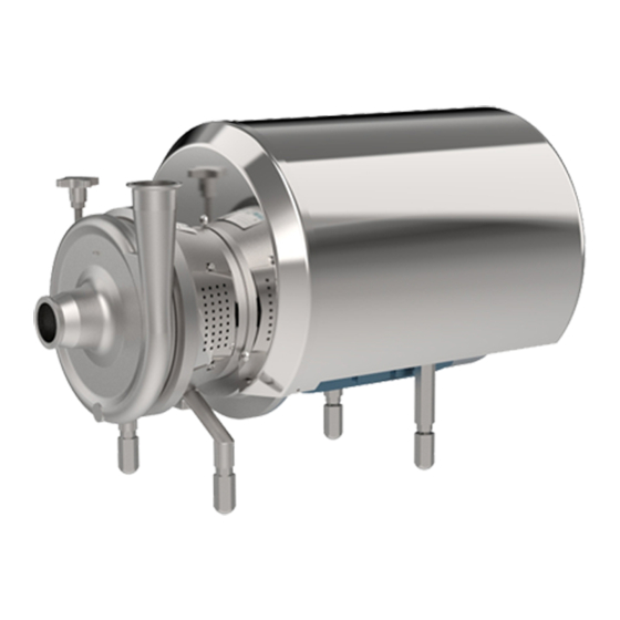
DESCRIPTION The CS series comprises single-stage centrifugal pumps with axial suction port, open centrifugal impeller and trapezoidal volute casing. All models have threaded connections for fittings according to DIN 11851 standards (unless otherwise requested) and all models are fitted with mechanical seals. The materials used for the components and the mechanical seal are chosen according to the liquid to be pumped. -
Page 6: Sound Pressure Level
SOUND PRESSURE LEVEL The sound pressure level of centrifugal pumps is the following (see table): Pump type CS 25-145 4-poles CS 25-175 4-poles CS 32-110 4-poles CS 32-145 4-poles CS 32-175 4-poles CS 32-210 4-poles CS 32-260 4-poles CS 40-145... - Page 7 2. RADIAL ALlGNMENT The radial alignment is controlled with a rule or a dial indicator or laser. By resting the rule on the periphery of the hubs and matching up two opposite teeth, you will have a sufficiently broad line of contact to check they match up throughout their surface area. Better alignment precision is obtained with the help of a dial indicator or laser (keep to radial tolerance Y). 3.
-
Page 8: Coupling With Spacer Type A..-Sp
7. DISASSEMBLY Remove the two set screws from the ring. Shift the ring by tapping it on the side with a nylon hammer in the areas the pins (reference lines) are housed. TAB. 1 MISALIGNMENT ADMISSABLE Type A10 A11 Axial X +0.3 +0.3 +0.5 +0.5 +0.7 +0.8 +1.0 +1.0 +1.0 +1.0 +1.0 +1.5 +1.5 +1.5 +1.5 Radial y Angular Z 0.10 0.10 0.20 0.20 0.30 0.40 0.40 0.50 0.50 0.60 0.90 1.10 1.30 1.70 1.70... -
Page 9: Suction And Inflow Conditions
SUCTION AND INFLOW CONDITIONS (NPSH = Net Positive Suction Head) NPSH of system (available NPSH) In order to ensure that pump operation is free from cavitation, it is essential to observe the maximum permitted suction lift ha geo max or the minimum allowable head hc geo min. NPSH of pump (required NPSH) The centrifugal pumps can operate correctly only if vapour has not formed inside. -
Page 10: Electrical Connection
For this reason, when sucking from a tank located at a lower level, the pipe must reach below the free surface of the liquid. In order to prevent the formation of vortices and avoid the risk of sucking in air, always keep a minimum head at the pipe inlet (h. min.) equal to at least the dynamic head plus a safety margin of 0.1 m (Fig.2). -
Page 11: Operation
OPERATION 10.1 PRELIMINARY OPERATIONS - Check that the pump turns freely under hand pressure. - Check that the clamp joining the pump casing and the lantern bracket is well tightened and that it cannot be easily unscrewed by hand. The tightening of the clamp must be carried out by means of a spanner and NOT by hand. -
Page 12: Spare Parts
SPARE PARTS 12.1 REFERENCE TABLE OF MAIN PARTS SUBJECT TO REPLACEMENT Pump type CS-CSX 32-110 25-145 25-175 Part -145 -175 -210 -175 -210 -260 -310 -350 * Mechanical seal D.20 D.28 D.43 D.55 EN12756-ISO3069 Pump casing “O-Ring” OR 6412 OR 215 OR 6670 OR 81300 6670... -
Page 13: Working Irregularities
WORKING IRREGULARITIES We are herewith listing some of the possible working irregularities which may occur using the pumps, with a table helping to find out the possible causes and how to solve the problem. Trouble: A) The pump does not run B) The delivery is not sufficient C) The pressure is not sufficient D) The pump stops priming E) Power absorption too high F) Leakages from the mechanical seal G) Short life of the mechanical seal H) Failure of the mechanical seal I) Anomalous vibrations and/or noise... - Page 14 TROUBLE p. 14...
-
Page 15: Seals
23) Voltage not suitable for the installed motor. - Replace the motor with one having a suitable voltage. 24) Mechanical seal worn. - Replace the mechanical seal. 25) Pump fluid or temperature not suitable for the assembled mechanical seal or its parts. - Verify the mechanical seal selection. 26) Non-cleaning when using fluids which tend to crystallize. - Increase washing cycles and don’t leave the product inside the pump for a long time. 27) Misassembly of the mechanical seal. -
Page 16: Single Mechanical Seals - Cs / Csx / Csk
SINGLE MECHANICAL SEALS - CS / CSX / CSK EXECUTION T / W STANDARD MECHANICAL SEAL “T” Standard execution foresees the assembly of an submerged internal mechanical seal on the product, housed behind the impeller in a specific tapered chamber so as to guarantee correct lubrication conditions. MECHANICAL SEAL WITH CIRCULATION "W" Internal mechanical seal with circulation forced by the pumped liquid. -
Page 17: Double Mechanical Seals - Cs / Csx
DOUBLE MECHANICAL SEALS - CS / CSX / EXECUTION Q COMPACT DOUBLE MECHANICAL SEAL “Q” Double mechanical seal with circulation of washing and cooling liquid. The function of flushing is that of cleaning, lubricating and cooling the seal; the liquid in circulation must be clean. If the seal is leaking, the flushing liquid will point out this fault. - Page 18 "Q" and "V" Exec. mechanical seal auxiliary flushing Upon the first start up, the filling of the pump, must be guaranteed. Furthermore, you must guarantee the full filling of the auxiliary systems, if present, such as the lubrication circuit of the external dual- seal (seal execution “Q”) or the external flushing circuit (seal execution “V”). Lack of compliance with the present requirements causes the dry operation of the pump and of the mechanical seal; consequently the mechanical seal can be overheated and damaged. The auxiliary services (optional) are the following: - flushing for the double external mechanical seal (seal execution “Q”) - external flushing for the internal seal (execution “V”).
-
Page 19: Disassembly
DISASSEMBLY 18.1 DISASSEMBLY OF CS PUMP "T/W" EXEC. (Version with single mechanical seal) A - Remove the screws (42-81) to disassemble shroud (41) and protections (80). - Remove screws (36) from motor and pull it off the pump. - Disassemble the front and rear foot (20-23) with the screws (24). -
Page 20: Disassembly Of Cs Pump "Q" Exec
E - Turn it over to access the screws (35) which allow you to separate the support (6) from the lantern bracket (5). F - Unscrew the screws (43) and remove the eccentric shroud (40) from the sup- port (6). N:B: Only for versions with shroud. -
Page 21: Disassembly Of Cs Pump "V" Exec
18.3 DISASSEMBLY OF CS PUMP "V" EXEC. Phase: carry out the operations as in parag. 17.1 (A-B-C) Phase: extract the rotating part of the mechanical seal (7) by turning the spring anticlockwise. Phase: after having disassembled the flushing pipes (39) separate the seal box cover (26) from the cover (2) by unscrewing the screws (28). -
Page 22: Reference Table For Assembly Allowance
REFERENCE TABLE FOR ASSEMBLY ALLOWANCE CS-CSX Dimensions Pump 25-145 34,9 35,2 25-175 34,3 34,6 32-110 29,8 30,2 32-145 37,8 38,1 32-175 36,3 36,7 32-210 37,3 37,8 32-260 41,4 41,7 40-145 38,8 39,2 Shims 40-175 39,4 39,8 40-210 38,9 39,3 40-260 42,4 42,8 A = Impeller/cover assembly allowance (imple-... -
Page 23: Bearings Maintenance
BEARINGS MAINTENANCE 20.1 BEARINGS MAINTENANCE FOR CS SERIES PUMPS In CS series pumps up to motor size 132 (5.5 ÷ 9.2 kW) the bearings installed are shielded and consequently do not need to be lubricated. 20.2 BEARINGS MAINTENANCE FOR CS - CSX SERIES PUMPS WITH HOUSING SIZE 160 ÷ 200 The bearings of CS pumps are sized for an operational life of 20,000 hours or more. -
Page 24: Bearings Maintenance For Csk Series Pumps
20.3 BEARINGS MAINTENANCE FOR CSK SERIES PUMPS The bearings of the pump support are lubricated using the oil bath method. The pump is supplied with the support without oil; fill the support before starting the pump, using oil supplied by C.S.F., or an equivalent type of oil. The procedure to fill with oil is the following: with the pump off, unscrew the release plug (pos. 74) and turn the bulb of the constant level oiler (pos. 76), as shown in the figure, then pour the oil through the release plug until it reaches the level of the hole at the side where the constant level oil-feeder is situated, as shown in the figure; then partially fill the bulb as a reserve and turn it to the closed position and screw the release plug back on. - Page 25 Remove the covers of the front and rear bearing (12) with seal rings (32) and gaskets (77). Remove the shaft (4) from the support (6). Complete the disassembly by remo- ving the bearings (8-9) and Speedi sleeve rings (125) from the shaft (4). 20.5 ASSEMBLY Perform the disassembly steps in inverse order to assemble the...
- Page 26 CLEANING PROCEDURE The cleaning of stainless steel pumps depends on the process liquid. Typically the cleaning process should be developed by a plant responsible of sanitization. C.S.F. Inox recommends a fluid velocity between 1,5-3 m/s, with rinsing water and chemical agent like alkaline detergent and acid. Chemicals like hypochlorite and chlorine must be avoided because stainless steel could be damaged by corrosion.
- Page 28 Distributed in the UK by..Pump Engineering Limited. Unit B1, Riverside Industrial Estate, Littlehampton, West Sussex, BN17 5DF, United Kingdom Tel: 01903 730900 - Fax 01903 730234 email: sales@pumpeng.co.uk Web: www.pumpeng.co.uk All the instructions, data and representations (in whatever way executed) listed in this publication are indicative and do not binding. C.S.F. does not stand surety or undertake any obligation for the utilisation of this document and for the information contained.
Need help?
Do you have a question about the CS 25-145 and is the answer not in the manual?
Questions and answers