
Related Manuals for CSF Inox TS Series


Summary of Contents for CSF Inox TS Series
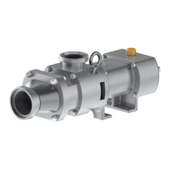
- Page 1 TECHNICAL SERVICE +39 0522 869832 TWIN SCREW PUMPS TS RANGE INSTRUCTIONS FOR INSTALLATION, OPERATION AND MAINTENANCE...
-
Page 2: Table Of Contents
Contents INTRODUCTION ............................3 Symbols used ............................. 3 Descriptive notes ..........................4 Use ..............................4 Enclosed documentation ........................4 SAFETY WARNINGS ............................ 5 Foreseen use ............................5 Improper use ............................. 5 Dangers arising from the use of the machine ................... 6 Particularly dangerous points ...................... - Page 3 Preliminary operations ........................20 Operation ............................20 7.2.1 Fluid temperature ........................20 CIP/SIP ............................. 21 7.3.1 Flushed double mechanical seal ....................21 7.3.2 Single mechanical seal ......................21 DISASSEMBLY OF THE TWIN-SCREW PUMP .................... 22 ASSEMBLY OF THE TWIN SCREW PUMP ....................31 ROUTINE MAINTENANCE ........................
-
Page 4: Introduction
1 INTRODUCTION This manual contains the instructions for the C.S.F. TS pumps relative to receiving delivery, installation and maintenance. The information given herein is of a general nature. Specific information for each version is given in the respective annexes. C.S.F. INOX SpA reserves the right to amend or modify the content of this manual without prior notice. -
Page 5: Descriptive Notes
NOTICE Identifies a risk of damage to material goods if not avoided. 1.2 Descriptive notes Twin-screw displacement pumps are machines with two counter-rotating shafts, synchronized by a gear placed externally to the pumping casing. The two shafts support as many rotors, which engaging, rotate inside a gauged stator and transfer fluid volumes separated from the suction casing to the discharge casing. -
Page 6: Safety Warnings
2 SAFETY WARNINGS The following occurs during operation: DANGER - Electric parts are under tension. - Mechanical parts are moving. - Pump casing, pipes and couplings under internal pressure. Therefore, do not remove any protection or locking device; do not loosen screws or fastenings, as this can cause serious damage to persons or objects. -
Page 7: Dangers Arising From The Use Of The Machine
- Pumping of acids or abrasive liquids, unless otherwise approved by our company; - Pumping of gas or gaseous substances; - Closing the outlet valve; - Reversing the flow, unless otherwise approved by our company; - Dry start, etc. DANGER The pump must always be used in an environment suitable to the level of protection of the motor. -
Page 8: Potentially Explosive Atmosphere
The pump must be protected by the costumer in a way that prevents people from inserting their hands in the indicated openings while the rotors are moving. In case of operations with the rotors stopped, ensure the motor cannot start accidentally. The risk is greater if the tubes are disassembled and the pump is open. 2.5 Potentially explosive atmosphere Follow the indications on explosion protection given in this section in case of operation in potentially explosive atmospheres. -
Page 9: Maintenance Warnings
NOTICE Make sure that the temperature of the fluid processed by the pump does not change abruptly. If this is inevitable, stop the pump for enough time (see par. 7.2.1) If the pump is supplied with a bare shaft, when selecting the coupling motor it is necessary to consider the following conditions: - The temperature limit allowed to the flange and drive shaft must be higher than the temperature generated by the pump;... -
Page 10: Guarantee
3 GUARANTEE All products manufactured by C.S.F. Inox are guaranteed to the purchaser, for one year from the date of purchase, against hidden defects in materials or manufacture, providing that they are installed and used according to instructions and recommendations of the manufacturer. Excluded from the guarantee other than distinctive wear and tear are repairs to damage caused by improper use, abrasion, corrosion, negligence, defect of installation, non-observance of inspection and maintenance, use of non-genuine spare parts, cause of accident or fortuity and from any action carried out by the purchaser not according to the... -
Page 11: Pump Description
4 PUMP DESCRIPTION This chapter reports the technical features of the pump, paying special attention to the types of mechanical seal used. 4.1 General description of the machine 4.2 Technical description of the machine Bare shaft pump Pos. Description Inlet connection Pump cover Pump casing Intermediate Casing... -
Page 12: Mechanical Seals
4.3 Mechanical seals The mechanical seal is a device designed to retain the fluid so that it does not get out of the pump. It consists of two sliding surfaces, one rotating in relation to the other, kept in axial contact by the pressure generated by the fluid (hydraulic force) and by the presence of components, such as springs or bellows (mechanical force). -
Page 13: Double Flushed Mechanical Seal
4.3.2 Double flushed mechanical seal Pos. Component Rotary gasket Rotary ring 1 Fixed ring 1 Frame Guide ring Spring Fixed ring 2 Rotary ring 2 Centering spacer Here are the flushing parameters: Maximum pressure of the flushing system: 16 bar Minimum flow rate of the flushing system: 0.5 l/min For applications with high sanitary requirements, we recommend using a non-pressurized system to avoid... -
Page 14: Transportation
5 TRANSPORTATION 5.1 Transportation The packaging of all pumps manufactured by C.S.F. Inox S.p.A. is defined when placing the order. Unless prior arrangements, the goods are packed only for transit conditions and not for long-term storage; if it should be necessary to store the pumps outside, the pumps must be appropriately covered in order to protect the electrical parts (motor drive) from rain, dust, humidity etc. -
Page 16: Installation
6 INSTALLATION 6.1 Pump preparation DANGER Position the pump over a plain surface. DANGER Do not start the pump without protections to avoid contact hazards!! The entire machine must be protected from any static charge. The connection between the drive shaft and the pump shaft must be protected from contact hazards! WARNING There must be enough space around the pump to allow for maintenance operations. -
Page 17: Motor Transmission Couplings
6.2 Motor transmission couplings Drive for independently mounted is transmitted via flexible couplings designed to absorb impact and torsional vibration. These couplings compensate for both angular and radial misalignment and can sustain variations in load and rotation inversion. The couplings are sized in compliance with DIN 740/2 standards. A coupling is sized so that the maximum moment transmitted by the coupling in different operating conditions is less than the maximum permissible strain for the coupling itself. -
Page 18: Connection To The Piping
Subject to authorization, it is possible to reverse the fluid movement changing the direction of rotation of the motor. Such operation is allowed for short periods at reduced differential pressures. For more information, please contact C.S.F. via the contact details in the end of this manual. 6.4 Connection to the piping Before connection clean the piping and remove foreign bodies (e.g. -
Page 19: Checks Prior To Start-Up (!)
6.5 Checks prior to start-up (!) If cleaning or repairs have been performed or if the first start-up is about to be carried out, ensure all the screws are correctly and completely screwed before starting the pump. In case of pumps for hazardous fluids, comply with the indications provided for such materials. The costumer must ensure that the pump is installed in the right position and with all the necessary safety devices (sensors, switches, pressure gauges, etc.)! The pump must always be filled with the product before the start-... - Page 20 When starting the motor, current absorption raises (5-6 times the nominal value) for a very short period; if the network cannot bear this absorption increase, we advise to use star or delta starters or other systems (for example auto-transformer). C.S.F. Inox S.p.A. is not liable for damages to persons and/or objects in case of non-observance of technical directions and laws.
-
Page 21: Operation
7 OPERATION 7.1 Preliminary operations - Check that the pump turns in the marked direction. - The suction pipe and the pump must be filled with liquid. Two possible cases can be distinguished: a) When the pump must operate with a negative suction head, it must be filled by introducing liquid into the pipes. -
Page 22: Cip/Sip
Temperature Waiting time [s] difference [°C] 7.3 CIP/SIP The twin-screw pump can perform Cleaning/Sterilizing in Place launch. If one wishes to use the pump for processing and for washing and sterilization purposes, it is necessary to notify CSF SpA during the selection phase, in order to receive a machine suitable for the performance requested and for the processed fluids. -
Page 23: Disassembly Of The Twin-Screw Pump
8 DISASSEMBLY OF THE TWIN-SCREW PUMP DANGER Electricity Electrical shock hazard. Electrical connection/disconnection operations on the pump must only be ‒ performed by qualified personnel. WARNING Improper maintenance Injury hazard. Only qualified maintenance technicians are authorized to perform maintenance ‒ operations. - Page 24 NOTICE Improper maintenance Damaging the pump. Before performing such operations, disconnect the electrical motor from the power grid, remove the pipes providing the connection to the system, uncouple the pump from the coupling joint and position it on a flat surface. Moreover, the pump must be washed internally. Use only original C.S.F.
- Page 26 2- Removal of the rotors: • Loosen the fixing nuts (6) of the rotors (8)(9), blocking the rear gear with a wedge of soft material, as described in the figure below; • After the removal of the nuts (6), the studs (36) and the respective gaskets (7), pull out the rotors (8)(9);...
- Page 27 3- Removal of the outlet casing: • Unscrew the 4 screws (18) fixing the intermediate casing (3) to the bearings housing (4); • Pull out the intermediate casing (3) and the 2 centering pins (21); • Remove the fixed parts of the mechanical seals (12) from the intermediate casing (3), acting on the 6 fixing screws and on the 4 extraction holes in the seal flange;...
- Page 28 4- Removal of the synchronization gear: • Unscrew the 2 grooved nuts (27) blocking the gearing (24)(25)(26); • Loosen the 6 adjustment screws (31) of the synchronization; • Remove the driving gear wheel (24) on the drive shaft (42); • Remove the adjustable bush (25) and driven gear wheel (26) unit from the driven shaft (11); •...
- Page 29 5- Removal of the drive and driven shaft from the synchronization gear side. • Unscrew and pull the screws (22) of the bearing cover (19) and the washers (29); • Remove the bearing covers (19); • After removing the drive and driven shafts, take out the radial seal rings (45).
- Page 30 6- Removal of the shafts Remove the rotating shafts from the rear of the bearings housings (4).
- Page 31 7- Disassembly of the shafts: • Remove the external rings from the 2 needle bearings (14); • Remove the external spacers (16); • Remove the sets of 3 rear ball bearings (17); • Remove the Seeger rings (15); • Remove the internal rings from the needle bearings (14).
-
Page 32: Assembly Of The Twin Screw Pump
9 ASSEMBLY OF THE TWIN SCREW PUMP After an accurate check of the conditions of the shafts and bearings, assembling of the pump can be performed. Proceed as follows to assemble the twin-screw pump: 1- Shafts composition: • Insert the inner rings of the front needle bearings (14) on the drive shaft (42) and driven shaft (11) bringing them to the end of their stroke;... - Page 33 2- Insertion of the shafts in the bearings housing and the synchronization gear Fit the radial seal rings (45) on the front side of the bearings housing (4); • • Insert the shafts assembled in the previous point in the rear side of the bearings housing (4), bringing them to the end of their stroke.
- Page 34 3- Insertion of the synchronization gear Insert the adjustable bush (25) in the driven gear wheel (26), by inserting the fixing screws • (31) and the washers (29)(31) without tightening them; Splice the drive gear wheel (24) and the bush (25) and driven wheel (26) unit, assembled in •...
- Page 35 4- Assembly of the mechanical seals and pump casing • Insert the fixing grub screws of the mechanical seal on the drive shaft (42) and driven shaft (11); • Insert the external rotating parts of the mechanical seals (12), bringing them to the end of their stroke on the shafts and fixing them tangentially to the grub screws inserted in the previous point;...
- Page 36 5- Insertion of the rotors • Fix the gasket (10) in the housing on the pump casing (3); • Insert the inner rotating parts of the mechanical seal (12) on the drive and driven shafts, bringing them to the end of their stroke; Assemble both rotors (8)(9) simultaneously on the respective shafts, coupling them by using •...
- Page 37 6- Synchronization of the rotors Insert a wedge of soft material between the gear wheels • to block the gear (A); Rotate the shafts to ensure that the 6 synchronization • screws (31) are positioned at the center of the 6 slots (E); Insert the shims in the points (B)(C)(D) between the sides •...
- Page 38 7- Pump closing Fit the gasket (20) and the gear casing (5) on the bearings housing (4), fixing them with 4 • screws (18) and the washers (18); Insert the lubricant oil draining plug (32) with its own aluminum gasket (35) and oil level •...
-
Page 40: Routine Maintenance
10 ROUTINE MAINTENANCE The following paragraphs contain the indications regarding the routine maintenance operations of the twin- screw pumps. For any further information, please contact C.S.F. via the contact details in the end of this manual. 10.1 Pump monitoring DANGER Injury hazard due to contact with moving parts! - Do not touch the pump during operation. -
Page 41: Wear Parts
C.S.F. Inox declines all responsibility for damage or injury resulting from the use of non-original spare parts. 10.3.1 Bearings maintenance The operations on the bearings of the TS pumps can ONLY be performed by authorized CSF Inox personnel, therefore please report the need for maintenance operations. -
Page 42: Maintenance Table
10.5 Maintenance table Component Staff Operation Intervention timetable Flushing/quenching Specialized technician Check the correct operation of Hourly during start-up, and seal system the flushing/quenching system then weekly Replace the quenching fluid Every 3 months Leaks checking Weekly Coupling with the Specialized technician Check the alignment and the Weekly... -
Page 43: Cleaning Fluids
To process fluids with a temperature higher than 90°C and/or speed of rotation consistently higher than 2000rpm it is recommended the use of FDA lubricant oil with ISO VS 150 viscosity grade. Filling volumes: TS 65 approx. 0.40 liters TS80 approx. - Page 44 Suggested cleaning process: WARNING During cleaning process, the surfaces of the pump can reach high temperatures. Pay attention! 1) Pre-rinse with cold water (15-25°C) for 10-15 minutes to remove any residue. 2) Warm pre-rinse with water at 45-60°C for 10 minutes. 3) Rinse with alkaline solution at 70-95°C for 20-30 minutes.
-
Page 45: Working Irregularities
11 WORKING IRREGULARITIES We are herewith listing some of the possible working irregularities, which may occur using the pumps, with a table helping to find out the possible causes and how to solve the problem. Trouble: A) The pump does not run B) The delivery is not sufficient C) The pressure is not sufficient D) The pump stops priming... - Page 46 TROUBLE ● ● ● ● ● ● ● ● ● ● ● ● ● ● ● ● ● ● ● ● ● ● ● ● ● ● ● ● ● ● ● ● ● ● ● ● ● ● ● ●...
- Page 47 Fluid specific gravity higher than foreseen. Increase the installed motor power. Pumped fluid too viscous. Verify the pump size. Higher pump delivery during operation due to plant friction losses lower than foreseen. Adjust the pump at a lower working point or increase the plant friction losses. Rotation speed too high (when pump is controlled by an inverter).
- Page 48 Verify and adjust anchorage of the involved parts. Bearings not lubricated. Replace bearings and restore their proper lubrication, which must be topped up from time to time according to work conditions (see par. 10.6 Lubrication). Water seepage due to worn oil retainers. Replace worn parts.
-
Page 49: Removal From Service
12 REMOVAL FROM SERVICE 12.1 Temporary removal from service Short term: DANGER Remove product waste (cleaning) Switch off the main switch Clean the surfaces of the pump Long term: DANGER Remove product waste (cleaning) Switch off the main switch ... -
Page 50: Permanent Removal From Service
12.2 Permanent removal from service DANGER Disconnect power supply Discharge the liquids Send exhausted oils or greases to companies specialized in their treatment. -
Page 51: Appendix - Torque
A. APPENDIX – TORQUE The following table reports the torques for the TS65, TS80 and TS100 pumps. Size TS 65 TS 80 TS 100 Torque Torque Torque Screw Screw Screw [Nm] [Nm] [Nm] Suction casing - Rotor casing Rotor casing - Pump casing Blocking of the rotors (WAF 30) (WAF 30)
Need help?
Do you have a question about the TS Series and is the answer not in the manual?
Questions and answers