Table of Contents
Advertisement
Quick Links
Advertisement
Table of Contents

Related Manuals for Comet XRC-4523-OW


Summary of Contents for Comet XRC-4523-OW
- Page 1 Industrial X-Ray Cooler Manual XRC-4523-OW 4500 watt oil to water cooler...
- Page 2 COMET AG Herrengasse 10 3175 Flamatt Switzerland Phone: +41 31 744 9000 Fax: +41 31 744 9090 E-Mail: info@comet.ch Internet: www.comet-xray.com Protection Notice Dissemination as well as copying of this document, utilization or posting of its contents is not permitted unless formally granted.
-
Page 3: Table Of Contents
Contents 1. ABOUT THIS MANUAL ................6 1.1. Explanation of symbols and signs ............. 6 1.1.1. Safety symbols ............................6 1.1.2. Warning instructions ..........................6 1.1.3. Text designations............................ 7 1.2. Illustrations ....................8 1.3. Terms of warranty ..................8 1.4. Contact information ..................9 2. - Page 4 4.4. Unit components ..................18 4.4.1. Cooling circuit ............................18 4.5. Technical specifications ................18 5. TRANSPORT, PACKING AND STORAGE ..........20 5.1. Safety ......................20 5.2. Checking the delivery condition ............... 20 5.3. Symbols on the packaging ................ 21 5.4.
- Page 5 11.2. Returning the unit to service after decommissioning......44 11.3. Final decommissioning, disposal ............. 44 11.4. Disposal of operating materials ..............45 11.5. Return of the unit to COMET ..............45 12. WEAR PARTS AND SPARE PARTS ............. 46 13. ADDENDUM.................... 47 13.1.
-
Page 6: About This Manual
1. About this manual This document is manual for the cooling unit XRC-4523-OW. It is based on international safety regula- tions. This operating manual addresses the needs of the user of the unit. Its intention is to allow the safe operation of the unit. -
Page 7: Text Designations
DANGER Reference to immediate danger to human health. DANGER Failure to comply with this warning instruction will result in severe irreparable injury and even death. WARNING Reference to recognizable hazard to human health. WARNING Failure to comply with this warning instruction may result in severe irreparable injury and even death. -
Page 8: Illustrations
1.3. Terms of warranty General sale and delivery terms of COMET apply. The buyer accepts these terms, at the latest when signing the contract of purchase. The particular terms of warranty and duration of warranty of the unit in question can be taken from the contract documents as well as from the order confirmation. -
Page 9: Contact Information
Any form of unintended use of the unit and any structural change caused by the user without prior authorization in written form by COMET will lead to the termination of warranty as well the termina- tion of the declaration of conformation and will free COMET from product liability. This concern inclu- des safety devices as well. -
Page 10: Safety
2. Safety This chapter provides an overview of all important safety aspects for optimal protection of personnel as well as safe and trouble-free operation. Disregarding this operating manual and warning instructions specified therein may result in considera- ble danger. 2.1. Hints for the safe operation Conduct inspections on a regular time base. -
Page 11: Inadmissible Operating Conditions
The manufacturer is not liable for damage occurring when using the unit in a way it was not intended. When using the unit in a way it was not intended for, the manufacturer’s warranty given by COMET will expire. 2.2. Responsibilities of the unit operator 2.2.1. -
Page 12: Minimizing The Risk Of Injury
2.2.2. Minimizing the risk of injury To minimize the risk of injury the following measures have to be taken: Work on the unit may be carried out by qualified personnel only. The personnel involved with the unit have to be authorized and trained by the operator of the unit. -
Page 13: Specialized Knowledge
Specific competencies and responsibilities, which are essential for the work on and with the unit Adequate behavior at an emergency Maintenance per- Deep knowledge in the fields of: sonnel Mechanical engineering Electrical engineering Authorization for performance of the following tasks according to the standards of safety technology: ... -
Page 14: Personal Protective Gear
2.4. Personal protective gear Wearing the personal protective gear is required when handling the unit to minimize the health haz- ards. The following personal protective gear must always be worn when handling the unit: Protective footwear For the protection against heavy parts falling down and from slipping on slippery surface. -
Page 15: Caution Label
2.7. Caution label Danger spots on the unit are indicated corresponding to German safety regulation DGUV Vorschrift 9 "Sicherheits- und Gesundheitsschutzkennzeichnung am Arbeitsplatz" Caution labels on the unit must be easily readable at all times. Illegible caution labels must be ex- changed without delay. -
Page 16: Product Identification
XRC-4523-OW 3.2. Identification plate The identification plate is attached to the housing of the unit and contains the following specifications: Unit name, e.g. XRC-4523-OW Name and address of the manufacturer Name and address of the distributor Article number ... -
Page 17: Unit Description
NOTE The manufacturer is not liable for damage occurring when using the unit in a way it was not intended. When using the unit in a way it was not intended for, the manufacturer’s warranty given by COMET will expire. -
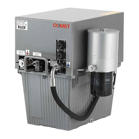
Page 18: Unit Components
4.4. Unit components The unit mainly consists of the following subassemblies. Additional unit information can be found in the diagrams contained in the addendum. Figure 4: Subassemblies (1) Heat exchanger (2) Cooling circuit (3) Casing 4.4.1. Cooling circuit In the cooling circuit the coolant is driven by the pump to the device that is to be cooled and back via the return flow. - Page 19 Coolant: Oil, Shell Diala S4 ZX-I Coolant capacity: ca. 23 liters Performance data 4500 W at ∆T = ≥ 20 K temperature difference between the cool- Cooling capacity: ant outlet temperature and the cooling water temperature Throughput: > 25 l/min at 350 kPa (3,5 bars) Mains voltage: 230 V AC + 10% / - 15%, 50/60 Hz Input power:...
-
Page 20: Transport, Packing And Storage
5. Transport, packing and storage 5.1. Safety WARNING Damage due to improper transportation! Injuries to persons and significant damage to property can occur in the case of im- proper transportation. When unloading the packed unit on delivery, as well as in-house transport, WARNING proceed very carefully and obey the symbols and instructions on the packag- ing. -
Page 21: Symbols On The Packaging
The packing material should only be removed just before the installation takes place. COMET advises to keep the transport pallet (if provided) for later transportation of the unit. Dispose packing material in accordance with environment protection requirements. -
Page 22: Handling With Industrial Truck
The packaging has only to be removed just before installation takes place. Protection caps for the coolant inlet and coolant outlet connections have only to be re- moved just before installation takes place. In order to store the units for more than 6 months, please consult COMET. -
Page 23: Preparing The Unit For The Further Transport
Mount the unit cover, see "Removing and mounting the unit cover" Pack the unit according to the transport conditions that can be expected. COMET advises to use original packaging, if available, or an equivalent packaging. Mark the packaging with appropriate symbols, see "Symbols on the packaging"... -
Page 24: Installation And Commissioning
6. Installation and commissioning 6.1. Requirements concerning the installation location 6.1.1. Installation location The surface of the location must be even. When choosing the installation location the following must be kept in mind: coolant inlet and coolant outlet connections must be easily accessible and all hoses must be installed without sharp bends. -
Page 25: Using The Unit For The First Time
6.2. Using the unit for the first time NOTE Risk of damage to the unit due to temperature fluctuations! In case the unit is stored outside the operating temperature for a longer period of time, let the unit rest at the installation location so long, until it has reached ambient temperature. Only then can the unit be put into operation. -
Page 26: Putting The Unit Into Operation
Connecting the unit electrically Requirements Coolant hoses connected, see "Connecting the coolant hoses" Cooling water hoses connected, see "Connecting the cooling water hoses" Coolant added, see "Adding coolant". Unit cover removed, see "Removing and mounting the unit cover" Procedure ... - Page 27 Starting up the unit Requirements Coolant hoses connected, see "Connecting the coolant hoses" Cooling water hoses connected, see "Connecting the cooling water hoses" Coolant added, see "Adding coolant" Unit connected electrically, see "Connecting the unit electrically" ...
-
Page 28: Controlling The Unit
7. Controlling the unit The unit is controlled by using the controls of the device that is to be cooled. All alarm and error signaling is only indicated on the control panel of the device that is to be cooled. 7.1. -
Page 29: Pressure Relief Valve
The pressure control valve is set by the manufacturer to a maximum pressure (factory setting: see "Technical specifications"). If any modification to this setting should be required, please contact the COMET service department to receive a briefing. NOTE The maximum pressure, which is reached by the device to be cooled, is affected by the length of the coolant hoses. -
Page 30: Cooling Water Controller
Procedure Remove the cover nut using the spanner (size 32). Use the spanner (size 36) to hold the valve in place. Loosen the counter nut using the spanner (size 32). Turn the adjusting screw clockwise by using spanner (size 19) to increase the maximum pressure. -
Page 31: Thermostat
7.3.4. Thermostat The coolant outlet temperature is monitored by a thermostat. Factory setting: see "Technical specifica- tions". To meet changing needs the switching point of the thermostat can be corrected using the ad- justment knob. Setting the maximum value of the coolant outlet temperature Procedure ... -
Page 32: Disruptions
In the event of fault diagnostics follow the guidelines detailed below: Only sufficiently qualified personnel may perform maintenance on the unit. If you cannot determine the error, please contact COMET services. 8.2. Disruption in operation The most common reason for disruption in operation of the unit is improper maintenance. Maintenance should be carried out regularly according to the maintenance intervals defined in chapter "Mainte-... -
Page 33: Troubleshooting
8.2.1. Troubleshooting For trouble shooting you may rely on the following: Alarm signaling within the safety circuit of the unit to be cooled Wiring diagram Flow chart Trouble shooting table given below Fault table Fault Possible cause Corrective measures Clearance by Unit does not... -
Page 34: Maintenance And Cleaning
9. Maintenance and cleaning Diligent maintenance is the prime factor for assuring an error-free and efficient operation of the unit. All the maintenance tasks contained in this chapter have to be performed according to the maintenance intervals. 9.1. Safety Working on the electrical equipment DANGER Electrical danger! Work on electrical installations may be carried out by trained and authorized electri-... - Page 35 Improper maintenance WARNING Danger of injury due to improperly performed maintenance. Improper maintenance can lead to personal injury or material damage. Disconnect the unit from all sources of power during maintenance work. Ensure the sufficient working area at the beginning of the maintenance work. ...
-
Page 36: Maintenance Schedule
Environmental issues NOTE Danger to the environment due to improper handling! Environmentally conscious and anticipatory behavior of staff avoids environmentally hazardous im- pacts. The following principles apply for environmentally conscious behavior: Environmentally hazardous substances must not get into the soil or into the drains. They should be kept in appropriate containers. -
Page 37: Preparing The Unit For Maintenance
Maintenance table Interval Activities to be carried out Criteria Personnel Regularly Check the coolant level and The coolant is filled up to the Operating per- replenish it, if necessary, see middle of the fill level indica- sonnel "Adding coolant" Inspect coolant hoses, con- Coolant hoses, pipes and Operating per- nections and pipes for cracks... -
Page 38: Disconnecting The Cooling Water Hoses
Disconnecting the coolant hoses Requirements Unit prepared for maintenance, see "Preparing the unit for maintenance" Coolant drained, see "Draining the coolant" Coolant cooled down to the ambient temperature. Tools and material required – Spanner (size 32) – Spanner (size 27) –... -
Page 39: Connecting The Coolant Hoses
Procedure Unscrew the connection screws for connecting the cooling water hoses to the unit using the water pump pliers. Use the spanner (size 22) for countering, in order to avoid the hy- draulic line from being destroyed. Secure the cooling water inlet and cooling water outlet connections with protection caps against soiling. -
Page 40: Connecting The Cooling Water Hoses
Remove the protection caps from the coolant inlet and coolant outlet connections of the unit. Connect an appropriate coolant hose to the coolant inlet and coolant outlet respectively. Screw the connection screws for connecting the coolant hoses to the unit using the span- ner (size 32). -
Page 41: Draining The Coolant
9.8. Draining the coolant Draining the coolant Requirements Unit prepared for maintenance, see "Preparing the unit for maintenance" Coolant cooled down to the ambient temperature. Tools and material required – Allen wrench (size 10) – Collection container – Filling funnel –... -
Page 42: Removing And Mounting The Unit Cover
Adding coolant Requirements Unit prepared for maintenance, see "Preparing the unit for maintenance" Coolant hoses connected to the unit, see "Connecting the coolant hoses" Unit cover removed, see "Removing and mounting the unit cover" Tools and material required –... -
Page 43: Cleaning The Casing
Ensure to adhere to safety regulations as detailed in chapter "Safety" 10.2. Repair procedures In case of malfunctioning during the warranty period the unit must be sent to the COMET service de- partment for repair (see "Contact information or the COMET services website under http://www.comet- xray.com/Service/Contact-Form). -
Page 44: Decommissioning And Disposal
11. Decommissioning and disposal 11.1. Temporary placing out of operation DANGER Electrical danger! Work on electrical installations may be carried out by trained and authorized electri- cians only. Switch off the unit before starting your work. DANGER Disconnect the unit from mains by pulling the mains plug. ... -
Page 45: Disposal Of Operating Materials
Contact COMET for take back of end-of-life units (see "Contact information") or the official COMET services website at http://www.comet-xray.com/Service/Contact-Form) or ask a company destined for disposal and recycling. 11.4. Disposal of operating materials The operating materials of the unit can be hazardous to the environment and to health. -
Page 46: Wear Parts And Spare Parts
COMET does not provide warranty service in case of damages caused by the use of spare parts made by manufacturers other than COMET. The type of the unit and the article number can be found on the identification plate of the unit. The corresponding numbers shown in drawings below as well as the part description are listed in the spare part list (table 7). -
Page 47: Addendum
13. Addendum 13.1. Performance diagram Item Designation Item Designation ∆T [°C] Temperaturedifference Oil to Water Cooling performance in watts To x-ray tube Water Cooling capacity 4500w... -
Page 48: Flow Chart
13.2. Flow chart Item Designation Item Designation Water outlet (hose nipple) Pump with motor Oil inlet (screw in con. M26x1,5) Relief valve Water inlet (hose nipple) Thermostat / Oil temperature Oil outlet (screw in con. M26x1,5) Evaporator Thermal switch Flow controller Throttle valve Level indicator Filter... -
Page 49: Wiring Diagram
13.3. Wiring diagram... - Page 50 Wiring diagram legend Item Designation Thermal switch Flow switch Capacitor Relay Pump Safety circuit i-Cooler Node Spare clamp...
-
Page 51: Dimension Drawing
13.4. Dimension drawing... - Page 52 Europe & RoW Asia COMET AG COMET Technologies USA, Inc. COMET China Herrengasse 10 100 Trap Falls Road Extension 1201 Gui Qiao Road CH-3175 Flamatt Shelton, CT 06484 Building 10, 1 floor Switzerland Pudong, Shanghai 201206 P.R.China T +41 31 744 90 00...
Need help?
Do you have a question about the XRC-4523-OW and is the answer not in the manual?
Questions and answers