
Subscribe to Our Youtube Channel
Related Manuals for Comet W0710


Summary of Contents for Comet W0710
- Page 1 User’s Guide W0710 W0711 W0741 W3710 W3711 W3721 W3745 W4710 W5714 W7710 Sensor with WiFi communication...
- Page 2 © Copyright: COMET SYSTEM, s.r.o. Is prohibited to copy and make any changes in this manual, without explicit agreement of company COMET SYSTEM, s.r.o. All rights reserved. COMET SYSTEM, s.r.o. makes constant development and improvement of their products. Manufacturer reserves the right to make technical changes to the device without previous notice.
-
Page 3: Table Of Contents
Table of contents INTRODUCTION ....................5 SAFETY PRECAUTIONS AND PROHIBITED HANDLING ........8 INSTALLATION ....................9 Hardware installation ................9 Provisioning and first setup ..............11 FEATURES ....................... 13 LCD display ..................13 Keyboard ..................... 15 WiFi Modes ..................16 Main page .................... - Page 4 IT security advices ................63 Firmware update .................. 64 Technical support and service .............. 64 TECHNICAL SPECIFICATION ................65 Power supply ..................65 General parameters ................65 WiFi radio ..................... 65 Communication protocols ..............66 Parameters of inputs ................67 Operating and storage conditions............
-
Page 5: Introduction
Device is equipped by USB-C connector which is used for powering of the device. Same connector can be used for device configuration if needed. Measured values can be shown on device web pages and can be transferred into data acquisition system COMET Cloud or COMET Database. 3 party data acquisition systems are supported via JSON, XML and Modbus TCP protocols. - Page 6 Schematic drawing of WiFi sensor: Dimensions: ie-wfs-Wx7xx-03...
- Page 7 Drawing of WiFi sensor with SMA antenna connector (option Wx7xxQ): Please see Technical specification for detail information about suitable antenna for devices with option Wx7xxQ. This antenna is not part of shipment. Dimensions for device with option Wx7xxQ: ie-wfs-Wx7xx-03...
-
Page 8: Safety Precautions And Prohibited Handling
Safety precautions and prohibited handling Please read the following safety precautions carefully before using the device and keep it in mind during use! Installation, commissioning, and maintenance must only be carried out by a qualified person in accordance with applicable regulations and standards. ... -
Page 9: Installation
Installation Hardware installation Select proper location for the device – bear in mind that the environmental conditions should meet requirement according to Operating conditions. Do not place device next to sources of electromagnetic interferences. The device has not a protection against the ingress of water and dust. - Page 10 Device can be mounted onto wall by optional holder LP100 – holder is available as optional accessory. LP100 package contains holder itself, installation material (wall dowels and screws), lock and keys. For security reason do not install device to higher position than 2 m above floor. ...
-
Page 11: Provisioning And First Setup
Provisioning and first setup Access point mode – newly purchased device is set into access point mode. Access point mode is signalised by symbol AP on the LCD display. In case this symbol is not shown or there is symbol CL, please switch device mode manually by the buttons according to chapter Keyboard. - Page 12 Other settings – during initial device configuration other settings can be changed. Detail information about device settings is available in chapter Device setup. Save settings – For settings changes to be applied, it needs to be saved using the field Save or cancel. ...
-
Page 13: Features
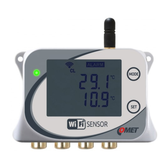
Features LCD display WiFi sensors are equipped with LCD display for showing current measured values and device state information. Showing of measured values at LCD display can be enabled for each value separately. When LCD display is deactivated and buttons are pressed, LCD display is temporarily activated with status information. - Page 14 from system alarms. System alarms designed for diagnostic of the device failure. Security enabled This symbol is shown when device security is enabled. Configuration session This symbol is shown when configuration session is under progress. Only one configuration session is possible at one moment. That means setup from other places is blocked when configuration session is started.
-
Page 15: Keyboard
Keyboard At the device body are two buttons MODE and SET. These buttons can be used for following actions: Manual switching between Client and Access point mode Showing of device IP address Mute of the acoustic Showing RSSI value at LCD display ie-wfs-Wx7xx-03... -
Page 16: Wifi Modes
WiFi Modes Device supports two WiFi modes. AP mode which in intended for initial provisioning into WiFi network and Client mode. Client mode is used when device is connected to infrastructure access point. When Client SSID is blank device is automatically switched into AP mode. Newly purchased device has blank SSID. - Page 17 Tile Description This tile starts Settings of the device. Advanced options menu. At this menu can be Mute of acoustic done and testing email and testing cloud message can be sent. There are accessible service options like a detection of Digi probes, firmware update and download of diagnostic file.
-
Page 18: Models Of Wifi Sensors
This chapter contains list of available models of WiFi sensors. Difference between models are types of inputs and ranges of measured values. Each measured quantity has assigned input channel. End-user cannot change type or range of measured quantities. W0710 ____________________________________________ Single channel compact thermometer This model of device measures temperature from probe which is connected to bottom part of the device. - Page 19 W0711 ____________________________________________ Single channel thermometer for external Pt1000 probe This model is designed to measurement from one external probe Pt1000/C. Probe is not a part of shipment and can be ordered separately. Device is suitable for monitoring places where probe is placed only, and device body is located outside the measured environment.
- Page 20 W3721 ____________________________________________ Thermometer-hygrometer for two external probes This model is designed to measurement of temperature and relative humidity from two Digi/E probes. Probes are not a part of shipment and can be ordered separately. It can be selected one of the computed humidity values (dew point, absolute humidity, specific humidity, mixing ratio, specific enthalpy, or humidex).
- Page 21 W4710 ___________________________________________ Compact sensor with temperature, relative humidity, barometric pressure and CO concentration measurement This model is designed to measurement of temperature, relative humidity, barometric pressure, and CO concentration of air. Temperature and relative humidity are measured by probe which is part of shipment and may to be detached from device body.
- Page 22 W5714 ____________________________________________ Compact sensor for measurement of CO concentrarion This model measure CO concentrarion of the air from internal sensor. Device should be located into measured environment directly. ie-wfs-Wx7xx-03...
-
Page 23: Device Setup
Device setup Conventions Configuration session Device setup uses a feature called configuration session. Once a device setup is started settings can be changed according to needs. All changes of setup are kept inside temporary memory. Settings changes are applied after saving. -
Page 24: General Settings
Globally disabled features Some device features can be globally enabled or disabled. Good example of such feature is LCD display. It can be globally disabled at General settings. Showing measured values at LCD display can be disabled for each channel separately. - Page 25 Change of device time is applied after saving whole settings. Be aware that improper changing of time zone without proper changing current time can cause wrong data interpretation at COMET Cloud history. ie-wfs-Wx7xx-03...
- Page 26 Due to natural behaviour of https and certificates at local networks it may to be needed assign security exception at web browser. COMET root certificate can be obtained on request. Be aware in case of administrator password is lost, device need to be...
-
Page 27: Measurements Settings
Measurements settings Settings of global features related to measurement. Available setup options depend on device type. Devices with temperature measurement can select between °C and °F. Dew point unit is same as temperature unit. Devices with humidity measurement allow for one of computed values from the list: Dew point, Absolute humidity, Specific humidity, Mixing ratio, Specific enthalpy, or Humidex. -
Page 28: Channels Settings
In case of channel name is left blank, default channel name according to selected language is used. Be aware that after changing channel name, a new channel is created inside COMET Cloud or COMET Database. Each channel can have two independent alarms thresholds which can be configured separately. - Page 29 WiFi sensors have capability to send email in case of alarm on channel is activated. Up to four email recipients can be configured. Addresses of email recipients are configurable at Email protocol settings. Each recipient can be enabled or disabled separately at alarm settings. Image above illustrates how settings of alarms works.
- Page 30 limit for longer time than is set delay. Alarm state persists till measured value goes under limit with hysteresis (50 % - 2 % = 48 %). Recalculation of measured values Measured values can be re-calculated using linear equation. This option can be enabled when some correction of measured values is needed.
-
Page 31: Alarms Settings
Alarms settings Alarm setting page allows for globally enable or disable audible and optical LED signalisation. There is option to enable local or remote mute of as well. System alarms System alarms are used to diagnose functionality of measurement chain including device or connected probes. -
Page 32: Network Settings
Network settings WiFi Client For usage of WiFi sensors at final deployment it needs to be device connected into infrastructure access point. Setup of connection parameters (SSID and password) is done at the WiFi client menu. Scan item shows WiFi networks at range. - Page 33 Setup of LAN parameters for Client mode. It can be used static IP address or IP address can be obtained from DHCP server automatically. By default, is DHCP option enabled. In case of static IP address need to be used, please contact your network administrator.
- Page 34 AP mode AP mode is intended for device provisioning and for a first setup. WiFi sensor comes into AP mode when SSID for WiFi client mode is blank. Device can be switched into AP mode by the device buttons manually if needed. When device is switched into AP mode by buttons and there is no other communication with WiFi sensor, device is switched back to client mode automatically after 10 minutes.
- Page 35 Device model Default power mode W0711 High performance W0741 High performance W3711 High performance W3721 High performance W3745 High performance W5714 High performance W0710 Normal performance W3710 Normal performance W4710 Normal performance W7710 Normal performance ie-wfs-Wx7xx-03...
-
Page 36: Protocols Settings
Device can send keep alive emails and repeat warning emails when alarm on channels persists. In case of COMET Cloud or COMET Database is used, it is not mandatory set sending emails from device itself. COMET Cloud and COMET Database have independent way how to send warning emails. - Page 37 In addition to the correct setup of SMTP server connection, the address of email sender and addresses of recipients needs to be set. WiFi sensors support up to four recipients which can be for each type of email enabled independently. It can be set email at text or html format according needs. Alarm repeat interval can be selected at range 10 min to 12 hours.
- Page 38 Proper settings of SMTP parameters can be tested at Advanced options menu accessible from main page. At first step need to be email and SMTP connection properly set at settings. After that email can be tested. Return codes are described at table below. Last state Description Unknown...
- Page 39 Error 4 Connection was instantly closed by server. Please make sure that set proper address of SMTP server and make sure that TLS option is not required. Error 5 Wrong response to welcome HELO or EHLO command. It seems stat opposite server is not a SMTP server or server requires TLS connection which is not enabled at the device.
- Page 40 Modbus TCP. Vision software Settings of TCP communication port for PC software - COMET Vision or WifiSensorUtility. Port is set to 10001 by default and may to be changed according to requirements. WiFi sensor here act as a TCP server.
-
Page 41: Cloud Protocol Settings
Cloud. COMET Cloud is a paid service. Each WiFi sensor comes with 3 moths free trial period for COMET Cloud. It allows to test features of COMET Cloud without any additional costs. For the device to be visible at COMET Cloud, it needs to be registered into Cloud. - Page 42 COMET Database is described at manual for COMET Database. Sending interval can be adjusted at range 10 sec to 12 hours. Enabled feature of Asynchronous messages allows to send messages when alarm occurred or is cleared. Memory for unsent readings can be deactivated if needed.
- Page 43 Error 2 DNS resolve error. Please make sure that is set proper URL for Cloud server and IP address of DNS server is correct. Error 3 Unable to create Cloud socket. Please contact support. Error 4 Unable to open TCP/TLS connection to Cloud server. Please make sure that is set proper URL, server is running, and ISP connectivity is available.
-
Page 44: Communication Protocols
Communication protocols Modbus TCP Modbus TCP protocol allows for measured values from device to the 3 party SCADA software. Modbus TCP server supports two connections (sockets) simultaneously. Default TCP port is 502. Modbus device address (Unit Identifier) can be arbitrary. Modbus write command is not supported. Brief description and example in Python language is available at About / Library section of webpages. - Page 45 Measured value at channel 1 0x9C40 40000 INT*X … … … Measured value at channel 8 0x9C47 40007 State of alarm 1 at channel 1 0x9C48 40008 … … … State of alarm 1 at channel 8 0x9C4F 40015 State of alarm 2 at channel 1 0x9C50 40016 …...
- Page 46 INT*(X+2) 32bit measured value with increased resolution by 2. Value is transmitted via two 16bit Modbus registers. Most significant part of number is transmitted first (e.g. value 22.825 = reg1: 0, reg2: 22825). Error values are transmitted as numbers lower then -320000000 (e.g -320000011 = Error 11).
-
Page 47: Cloud Protocol - Json
POST with JSON data format. JSON protocol is described at this chapter. Python example of http server is available at About / Library section of webpages. There are two modes of Cloud protocol - COMET Cloud mode and COMET Database / User server. This chapter is described User server mode only. - Page 48 RSSI values structure: <Rssi>: { <Now>, <Sample> } Structure for channels: <Channels>: <Nr>, <En>, <Quant>, <Val>, <ValStr>, <Unit>, <Dec>, <Alarm>: [ <_Al1>, <_Al2> ], <AlarmLim>: [ <_AlLim1>, <_AlLim2> ], <AlarmMode>: [ <_AlMode1>, <_AlMode2> ] <Nr>, <En>, <Quant>, <Val>, <ValStr>, <Unit>, <Dec>, <Alarm>: [ <_Al1>, <_Al2>...
- Page 49 (RESULT_CONFIRM) <Sn> 8B length Serial number of the device (e.g. 20286614) <Desc> 64B length Device name at UTF-8 <Kind> 0 – 11 Identification of device type: W0710 W0741 W3710 T+RH W3711 T+RH W3721 T+RH W3745 T+RH W7710...
- Page 50 <Dec> 0 - 10 Number of decimal places State of alarm at the channel (1 = alarm) <_Al1> 0, 1 Alarm 1 at channel <_Al2> 0, 1 Alarm 2 at channel Alarm limit at float format transmitted via HEX characters. IEEE 754 Float number 72.0442 is transmitted as hexadecimal string 429016A0.
-
Page 51: Json And Xml Via Http Server
Message response Delivered messages to http(s) server needs to be confirmed by following response: <Result>, <Message> Parameter Type Range Description <Result> BOOL Response whether incoming message was successfully processed by the server. In case of server response is true, message is marked as successfully sent and message is removed from cache (if cache feature is not deactivated). - Page 52 XML structure XML file structure can be validated against XSD schema available at About / Library section of webpages. At same place are available examples of XML files as well. Description of tags at <root> key: Parameter Type Range Description <devname>...
- Page 53 <name>, <unit>, <value>, <alarm1>, <alarm2> where: Parameter Type Range Description <devname> 64B length Device name <devsn> 8B length Serial number of the device (e.g. 20280001) <time> RFC3339 Current device time <timeunix> 32bit Current device time as Unix timestamp unsigned (seconds since 01/01/1970) <synch>...
-
Page 54: Troubleshooting
Troubleshooting Factory defaults By the factory defaults procedure, the device is restored into same state as was newly purchased. Current device settings are lost including passwords and WiFi connection parameter. Provisioning procedure for connecting into WiFi network needs to be done again. Factory default procedure can be done locally only. -
Page 55: Forgotten Administrator Password
TSensor. This software is free for download at manufacturer webpages. Local IP address of WiFi sensor can be shown at COMET Cloud or COMET Database. To be able to utilize this feature, WiFi sensor needs to be connected to that platform. - Page 56 Error 2 A/D converter for measurement from Pt1000 probes is above high limit. It is likely that temperature probe is not connected, or cable is damaged. Please inspect probe for a damage or connect probe. Error 3 Measured value is outside expected range. Please contact technical support.
-
Page 57: Warning Exclamation Mark On Lcd
Error 37 Unknow type of Digi probe. Please update firmware version and after that detect Digi probe(s) again. Error 38 Communication error with memory for calibration data inside Digi probe. It is likely that Digi probe is not connected properly, or probe is damaged. -
Page 58: Battery Symbol At Lcd Or Wrong Device Time
Battery symbol at LCD or wrong device time Device time is maintained by internal RTC (real-time clock) circuit with coin- cell backup battery. Battery lifetime is designed for a whole device lifespan and is not exchangeable by the end-user. In case of battery sign at LCD display and red exclamation mark at the web pages are shown, it means that current time may not be correct. -
Page 59: Wifi Network Connection Problems
WiFi network connection problems In case of troubles with connection into WiFi network these steps may to be followed: 1. At first step please makes sure that are inserted proper WiFi connection credentials like SSID, password and encryption type. Credentials can be tested with another WiFi devices if needed. - Page 60 In case of WiFi sensor with SMA connector (option Wx7xxQ) is used, please make sure that antenna according Technical specification is used. Incompatible external antenna may to affect RF performance of WiFi sensor. Recommended signal strength (RSSI) is higher than -70 dBm (e.g. -55 dBm). Signal strength can be examined by following steps: 1.
-
Page 61: Recommendations For Operation And Maintenance
Recommendations for operation and maintenance Operation in application areas Before putting the device into operation, it should be considered, if device is suitable for the intended purpose. Device settings should be determined together with intended use case. In case that the device is part of a larger measurement system, instructions for its metrological and operational checks should be developed. -
Page 62: Recommendations For Calibration
LCD display or device webpages. b) Check whether measured values are properly transferred into data acquisition platform like is COMET Cloud or COMET Database. Data are transmitted according to selected sensing interval. c) Check history data inside data acquisition platform for any unexpected data outage or alarm states. -
Page 63: It Security Advices
IT security advices IT security is an important aspect of deployment of any device connected into wired or wireless networks. It is not important from application and measurement device standpoint only, but overall integrity of network infrastructure itself. Any not adequately secured network device or IoT device may to compromise security of network. -
Page 64: Firmware Update
Firmware update Device firmware can be updated via web pages – Advanced options / Service menu. In case of security is enabled, administrator permissions are required. Firmware downgrade is not supported via web pages. Latest firmware version can be obtained from manufacturer webpages or from technical support. -
Page 65: Technical Specification
Technical specification Power supply Supply voltage: 5.0 V to 5.4 V DC Consumption: Typ. 150 mA at high performance mode (max. 500 mA) Recommended power supply adapter: A1879 (Sunny SYS 1561-1105) Recommended cable: MP053 (USB A to USB-C length 1 m) Connector: USB-C General parameters... -
Page 66: Communication Protocols
WiFi security: Open, WEP, WPA / WPA2, WPA2-PMF, WPA3 WPA2 Enterprise (IEEE 802.1X) is not supported now WiFi modes: Client mode Access point mode (up to four clients connected simultaneously) Antenna: Standard device: External antenna not detachable Antenna specification for devices with Wx7xxQ option: ... -
Page 67: Parameters Of Inputs
Recommended calibration interval: 2 years W0711 ___________________________________________ Measured values: Temperature from external probe COMET Pt1000/C Range: -90 °C to +260 °C (sensor Pt1000/3850 ppm) -150 °C to +600 °C (for option W0711F) Measurement current ~250 uA Input accuracy (without probes): ±0.2 °C the at range below +100 °C... - Page 68 Probe connection: Two wire connection with capability for deviation compensation due to resistance of uses cable. Connection is done via CINCH (RCA) connector. Connection is described at Appendix Recommended length of probe Pt1000/C is up to 15 m. Length of probe cannot exceed 30 m. It is strongly recommended to use shielded cable of probe only.
- Page 69 Recommended calibration interval: 2 years W3710 ___________________________________________ Measured values: Temperature and relative humidity from a probe, which is part of shipment. Other humidity quantities are calculated from the measured temperature and humidity. Range: Temperature: -30 °C to +60 °C Relative humidity: 0 %RH to 95 %RH without condensation Dew point temperature: -60 °C to +60 °C Accuracy: Temperature: ±0.4 °C...
- Page 70 W3711 ___________________________________________ Measured values: Temperature and relative humidity from an external probe Digi/E. Other humidity quantities are calculated from the measured temperature and humidity. Range, accuracy, and response time: See manual for a particular Digi/E probe Probe connection: Digi/E probe is connected by 4-pin M8 ELKA 4008V connector. Connection of pins is described at Appendix Maximum length of cable for Digi/E probe cannot exceed 15 m.
- Page 71 W3745 ___________________________________________ Measured values: Temperature and relative humidity from an external probe Digi/E and up to three temperature from external probes Pt1000/C. Other humidity quantities are calculated from the temperature and humidity measured by the Digi/E probe. Digi/E probe range, accuracy, and response time: See manual for a particular Digi/E probe Digi/E probe connection: Digi/E probe is connected by 4-pin M8 ELKA 4008V connector.
- Page 72 W4710 ___________________________________________ Measured values: Temperature and relative humidity from a probe, which is part of shipment. CO concentration and barometric pressure from internal sensors. Other humidity quantities are calculated from the measured temperature and humidity. Range: Temperature: -30 °C to +60 °C Relative humidity: 0 %RH to 95 %RH without condensation Barometric pressure: 700 hPa to 1100 hPa concentration: 0 to 5000 ppm (optionally 0 to 10000 ppm)
- Page 73 Resolution: Temperature including dew point temperature: 0.1 °C Relative humidity: 0.1 %RH Barometric pressure: 1 hPa concentration: 1 ppm Recommended calibration interval: 1 year W5714 ___________________________________________ Measured values: concentration of air Range: 0 ppm to 5000 ppm (range 0 ppm to 10000 ppm as option) Accuracy: ...
-
Page 74: Operating And Storage Conditions
Accuracy: Temperature: ±0.4 °C Relative humidity: sensor accuracy: ±1.8 %RH at temperature 23 °C and humidity range 0 %RH to 90 %RH hysteresis: < ±1.0 %RH non-linearity: < ±1.0 %RH Barometric pressure: ±1.3 hPa at temperature 23 °C Dew point temperature: ±1.5 °C at ambient temperature T <... -
Page 75: Mechanical Properties
Storage humidity: 5 to 90 %RH Mechanical properties Dimensions (h x w x d): 93 x 81 x 32 mm without connected probes and cables Mass: ~ 120 g Case material: Polycarbonate LEXAN™ EXL1434T resin Ingress protection: IP30 End of operation In case of device decommission be aware that device may to contain confidential information like a password(s). -
Page 76: Appendix
Appendix Appendix 1: Accuracy of dew point and other humidity quantities Dew point temperature: Accuracy: ±1.5 °C at ambient temperature T < 25 °C and RH > 30 %RH Range: -50 °C to +60 °C Absolute humidity Accuracy: ±1.5 g/m at ambient temperature T <... - Page 77 Specific humidity * Accuracy: ± 2 g/kg at ambient temperature T < 35 °C Range: 0 g/kg to 130 g/kg Mixing ratio * Accuracy: ± 2 g/kg at ambient temperature T < 35°C Range: 0 g/kg to 150 g/kg Specific enthalpy * Accuracy: ±...
- Page 78 Appendix 2: Connection of Pt1000/C probe(s) connector Connectors for Pt1000/C probes uses CINCH (RCA) connector. Connection of for W0711, W0741, W3745 Pt1000 probe is shown below. Appendix 3: Connection of the Digi/E probe(s) connector Digi/E probe is connected by 4-pin M8 ELKA 4008V connector. Colour coding of wire connection for W3711, W3721, W3745 is shown at image below.
- Page 79 Appendix 4: Acoustic and optical LED operation diagram Image below described operation diagram of acoustic system at WiFi sensors. Device acoustic can be activated from two different sources. It can be activated from alarms on channel and from system alarms. To be device acoustic functional it needs to be globally enabled and enabled alarm source as well.
- Page 80 Image below described operation diagram of optical LED signalisation subsystem at WiFi sensors. LED signalisation can be activated from two different sources. It can be activated from alarms on channel and from system alarms. To be device LED signalisation functional it needs to be globally enabled and enabled alarm source as well.
- Page 81 HTTP webserver HTTPS webserver when device security is enabled Modbus TCP port (default port) 10001 Communication with software COMET Vision or WifiSensorUtility (default port) 5353 mDNS discovery protocol 30718 COMET discovery protocol Note: ICMP Echo (ping) is enabled at WiFi sensors.
- Page 82 Appendix 6: Tests with 3 party SMTP services WiFi sensors with firmware version 10.0.2.0 was successfully validated with following 3 party email services. This list is valid at date of creation 2021- 04-16. Not all services may to be available at all countries. Because these email services are from 3 party, we do not guarantee proper function with WiFi sensors or compatibility by any kind.
- Page 83 Appendix 7: List of available device options Following options for WiFi sensors are available and can be ordered with new devices. Option Order code SMA antenna connector instead W0710Q, W0711Q, W0741Q, W3710Q, W3711Q, W3721Q, W3745Q, W4710Q, non-detachable antenna W5714Q, W7710Q Higher temperature measurement W0711F, W0741F, W3745F range for Pt1000 inputs (-150 °C...
-
Page 84: Revision History
Revision history Document version Date Note IE-WFS-Wx7xx-01 February 2021 Initial document version for firmware version 10.0.2.0. IE-WFS-Wx7xx-02 Revision of chapter “Provisioning and April 2021 first setup” Added new troubleshooting chapter – “WiFi network connection problems” Added new appendix – “Tests with 3 party SMTP services”...
Need help?
Do you have a question about the W0710 and is the answer not in the manual?
Questions and answers