Advertisement
58
84
51 57
59
59
47(5x)
46
51
48
47(2x)
49(2x)
44
45
82
40 41 42
43 44 45
43
42
40
41
EXAMPLE:
00
Component Parts (Small #) Are Included
0
When Ordering The Assembly (Large #).
SERVICE PARTS LIST
SPECIFY CATALOG NO. AND SERIAL NO. WHEN ORDERING PARTS
M18 FUEL™ SAWZALL
M18CSX-0
MODEL NO.
83
46 47 48
64
89
47 49
52 63
64
63
57
52
60
80
30
60
62
34
88
87
27 28
34
29
(6x)
28
24
(2x)
21
®
Reciprocating Saw
2720-20
30
31
32
26
(4x)
18
19
20
23
1
See page 4 for
special service
notes
WIRING INSTRUCTION
SEE PAGE 5
74
90
70
76
50
(4x)
72
10
9
25
81
27
16
2
4
8
85
3
5
6
7
17
22
DATE
Aug. 2015
75
26
(2x)
73
70
76
71
86
27 71
72
2 3 4 5
6 7 8
Drwg. 1
Advertisement
Table of Contents

Subscribe to Our Youtube Channel
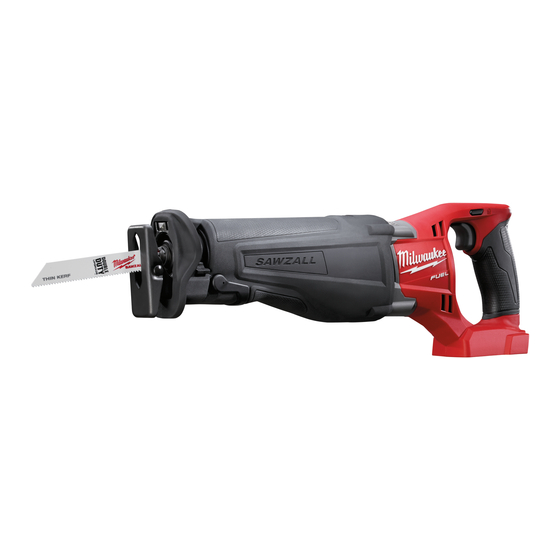
Summary of Contents for Milwaukee M18 FUEL SAWZALL M18CSX-0
- Page 1 SERVICE PARTS LIST DATE SPECIFY CATALOG NO. AND SERIAL NO. WHEN ORDERING PARTS Aug. 2015 ® Reciprocating Saw M18 FUEL™ SAWZALL WIRING INSTRUCTION 2720-20 M18CSX-0 MODEL NO. SEE PAGE 5 51 57 46 47 48 (2x) (4x) 47(5x) 47 49 52 63 47(2x) 27 71...
- Page 2 Concave side of disc spring (32) must face toward metal plate (31) When securing the orbit and bevel gear (30). slot (25), tighten screws (26) in the order shown. NOTE: Orbit Slot #25 has NOTE: Counter Weight of been removed from this view Pinion Gear of Crankshaft Assembly #88 for clarity (to reveal Connecting...
- Page 3 Bearing Retaining Plate (75) Drive Hub Bolt (74) Left hand thread Screws (26) Gearcase - Left (71) Gearcase - Right (28) Crankshaft Assembly (88) Do not wash crankshaft assembly (88) in solvent solutions; Wipe off only using clean, dry, lint-free cloth. Removing Crankshaft Assembly (88) from Left Gearcase (71) Remove, crankshaft assembly (88) from left gearcase (71) by separating / removing right housing half (28).
- Page 4 Shoe Pin Flats (both sides) Shoe Release Lever #22 Block To properly install the Shoe Release Lever #22 onto the Shoe Pin #23 do the following: Insert the shoe pin through the hole in the Place the tool on its side on a hard flat surface. gearcase insulator.
- Page 5 Route sleeved wires of the LED Assembly #76 as shown, pressing/ trapping sleeve up into the LED Tray #70. Place tray into the top groove between gearcase halves and tighten screws. Prior to installing the LED and Tray Assembly #90, route High Voltage Wire #92 around and through the Motor Cage Assembly #89 as shown.


Need help?
Do you have a question about the M18 FUEL SAWZALL M18CSX-0 and is the answer not in the manual?
Questions and answers