Advertisement
Quick Links
Advertisement

Related Manuals for Vibration Research ObserVR1000


Summary of Contents for Vibration Research ObserVR1000
- Page 2 Notes, Notices, and Cautions © 2021 Vibration Research Corporation is a registered trademark in the United States and other countries. Information in this document is subject to change without notice. Document last revised Tuesday, March 23, 2021 - Jenison, Michigan.
-
Page 3: Table Of Contents
Table of Contents ObserVR1000 Hardware Manual ......................... 1 Hardware Overview ......................... 4 Capabilities & Specifications ......................... 6 Installation ......................... 9 Connection ......................... 14 Inputs/Outputs ......................... 20 Troubleshooting & Diagnostics ......................... 28 Warranty... -
Page 5: Hardware Overview
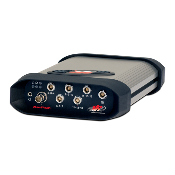
Hardware Overview Front and Back Panel Inputs/Outputs support@vibrationresearch.com... - Page 6 CONTINUED FRONT PANEL · The ObserVR1000 front panel has 16 input channel connections that support various analog input devices including IEPE transducers and smart transducers (TEDS). The Channel 1 connector is a BNC. The Channel 2 to 16 connectors are 9-pin LEMO, and each support 1 triaxial transducer or 3 single axis transducers.
- Page 7 · The USB port connects to optional data acquisition interfaces and external hard drives supplied by Vibration Research. The USB port is capable of supplying 0.9Amps. · The GPS port connects to an optional GPS supplied by Vibration Research. The GPS is powered by the ObserVR1000 and includes position updates at about 1Hz as well as GPS time base synchronization.
-
Page 8: Capabilities & Specifications
Capabilities & Specifications Item Check List · ObserVR1000 I/O unit · IEC C13 AC power cable · Charger · Drive cable · Network (Ethernet) cable · Software installation CD · ObserVIEW Quick Start Guide · Hardware Manual ObserVR1000 General Specifications ·... - Page 9 Hardware Safety Documentation · The mains supply cord is part of the separately certified power supply. Vibration Research is responsible for supplying the correct power supply for the country in which it is sold. · The external power supply should only be supplied by Vibration Research.
-
Page 10: Installation
Installation Intended Use The ObserVR1000 is a high sensitivity, low noise, and low voltage data recorder to be used to record signals such as those generated by accelerometers and other sensors that generate signals in the ±10V range. Installation Precautions CAUTION: Before performing any of the following procedures, read and follow the safety instructions. - Page 11 · Do not use the device for any purpose other than its intended use. · Do not incinerate the ObserVR1000 or its internal or external batteries. Site Requirements Before installing the device, verify that the site selected for the device meets the following site requirements: ·...
- Page 12 160mm x 250mm x 81mm Storage and Transportation The ObserVR1000 can be stored in a non-operating state in an ambient temperature of -40° to 185°F (-40° to 85°C). For optimal battery life, the ObserVR1000 should be stored in an ambient temperature of 59° to 86°F (15°...
-
Page 13: Connection
Dispose of batteries according to your local environmental laws and guidelines. NOTE: For first use of the ObserVR1000, connect the battery to an electrical outlet using the AC adapter. For best results, operate the ObserVR1000 with the AC adapter until the battery is fully charged. - Page 14 15 seconds of charging and within the allowable battery temperature range, the internal battery requires servicing. The ObserVR1000 can still be operated with an AC adapter or an external battery, but the internal battery will be unavailable.
- Page 15 CAUTION: Terminals on the unit shall be connected only to passive load transducers or source transducers that apply no more than 10V to the circuit that originates from the ObserVR1000 (or other value that equates to not more than 33Vac rms /46.7V peak or 70Vdc total on the circuit).
- Page 16 Connection CONTINUED Connecting the Device to Software The user can control the ObserVR1000 with one of the three Vibration Research software applications. Each software package offers a different set of capabilities when paired with the ObserVR1000. VibrationVIEW: To connect the ObserVR1000 to the VibrationVIEW software for vibration control, please refer to the VibrationVIEW Quick Start Guide.
- Page 17 This portable transmitter with its antenna has shown compliance with FCC’s SAR limits for general population/uncontrolled exposure. The maximum listed SAR level is 1.07 W/kg (body). The antenna used for this device must not be co-located or operated in conjunction with any other antenna or transmitter.
-
Page 18: Inputs/Outputs
CHANNELS 2 TO 16 LEMO INPUTS The LEMO input connectors are LEMO EXG.0B.309.HLN. An example LEMO cable side connector that mates with the ObserVR1000 is FGG.0B.309.CLAD52. There are a variety of configurations available; consult LEMO's documentation for the full range of options. - Page 19 Images courtesy of LEMO. Digital I/O TACHOMETER CONNECTOR The ObserVR1000 tachometer interface contains two tachometer inputs, one digital input, one digital output, and two auxiliary 5V power supplies. The interface uses the same connector as the LEMO inputs. support@vibrationresearch.com...
- Page 20 Input signals in this configuration must be bipolar, where the voltage swings above and below ground. Input signals may be up to 1MHz. In this configuration, the ObserVR1000 detects zero crossings in the negative-going direction. Zero crossings will only be detected after the input signal exceeds a positive-going "arming"...
- Page 21 48Wh / 3.2Ah Lithium-Ion battery with a nominal voltage of 15V, and takes about 3 hours to charge at room temperature. If the ObserVR1000 internal battery has <20% charge remaining and an external battery is connected, the ObserVR1000 will attempt to charge the internal battery to 20% using the external battery.
- Page 22 "EXTERNAL BATTERY CHARGER" and "ObserVR1000 CHARGER." The power adapter for the external battery charger will not plug into the ObserVR1000, but the power adapter for the ObserVR1000 will plug into the external battery charger. The output voltages of the power adapters are different, and the ObserVR1000 power adapter will not provide sufficient voltage for the external battery charger.
- Page 23 ObserVR1000. The ObserVR1000 GPS connector is a D-Sub 9 position receptacle (sockets). Rx and Tx are shown with respect to the ObserVR1000. The GPS module data output should be connected to pin 3 of the ObserVR1000 (GPS Data Rx) and the GPS module data input should be connected to pin 2 of the ObserVR1000 (GPS Data Tx).
-
Page 24: Troubleshooting & Diagnostics
STATUS LED The three LED indicators on the front panel display operator status. All three indicators will be off when the ObserVR1000 is off or being reset. The status indicator will blink green when the ObserVR1000 is operating as normal. The color, blink rate, and blink duty cycle encode different... - Page 25 Green Solid Booting internal firmware. Blue Solid Rebooting to new firmware version. Solid Program termination. ObserVR1000 is off. INFO LED Info Color Blink Pattern Info Indicated Power enabled on at least one input, Green Solid and no faults detected on any of the inputs.
- Page 26 SD slot and then releasing the card. Although it is possible to remove the SD card at any time, the ObserVR1000 must complete writing any data to the SD card prior to removal. If the lighted push button is blinking red, then the system is actively writing to the card and it is not safe to remove the card.
- Page 27 Activating the on/off power switch for 1 second or more while the ObserVR1000 is off will turn it on. Activating the on/off power switch for 2 seconds or more while the ObserVR1000 is on will turn it off within 30 seconds.
- Page 28 Indicated Fault Troubleshooting Code Power sequencing Return the ObserVR1000 to Vibration error Research for service. Plug ObserVR1000 into line power to Internal battery charge battery. ObserVR1000 may be discharged operated from line power while internal battery is charging. Internal battery...
- Page 29 Disconnect AC line adapter. Check if correct adapter is being used; the Line input voltage supplied adapter is labeled "ObserVR1000 or current too high CHARGER." Check for damage to line adapter. Inter-chip Return the ObserVR1000 to Vibration communication Research for service.
- Page 30 Press the stop button to stop recording. The stop button will blink solid green for 2 seconds if the recording is completed successfully. The stop button will flash red 8 times to indicate a recording error. Refer to the VR Mobile section in the ObserVIEW Help file. ObserVR1000 Hardware Manual...
- Page 31 During ObserVR1000 shutdown, the start and stop buttons will illuminate white when the shutdown begins and turn off when shutdown is complete. The ObserVR1000 can be forced to net boot over Ethernet. This mode should only be used for diagnostic purposes in coordination with Vibration Research support.
-
Page 32: Warranty
Warranty Vibration Research warrants the ObserVR1000 to be free of defects in materials and workmanship for a period of one (1) year from the date of purchase. This warranty covers hardware failure under normal operating conditions and does not cover damage due to ordinary wear and tear, nor neglect, misuse, or failure to follow instructions relating to the hardware’s use.
Need help?
Do you have a question about the ObserVR1000 and is the answer not in the manual?
Questions and answers