Table of Contents
Advertisement
Quick Links
Advertisement
Table of Contents

Related Manuals for Vibration Research VibrationVIEW

Summary of Contents for Vibration Research VibrationVIEW
- Page 1 VibrationVIEW VIBRATION CONTROL QUICK START GUIDE...
- Page 2 If you have questions regarding your system, please contact your Vibration Research representative or our product support staff. +1.616.669.3028 8am to 5pm Monday-Friday (EST) support@vibrationresearch.com VibrationResearch.com © 2021 Vibration Research is a registered trademark in the United States and other countries. Vibration Research | VibrationVIEW | ObserVR1000 | ObserVIEW ®...
-
Page 3: Table Of Contents
ShockVIEW Test Set-up ......20 FDRVIEW Test Set-up ......22 Multi-Axis Test Set-up ......24 Automatic Report Generation ....26 Troubleshooting Connection Errors ..28 Tips & Tricks ........... 30 Important Changes to VibrationVIEW ..23 Key Mapping .......... 34... -
Page 4: Setting Up The Hardware
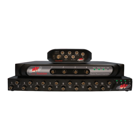
3. Connect the amplifier’s input to the OUT connector on the rear panel of the ObserVR1000. 4. Connect an accelerometer to channel 1 on the front panel. Other accelerometers can be connected to channels 2 to 16. 5. Turn on the ObserVR1000. 2 • VibrationVIEW Quick Start Guide... - Page 5 ObserVR1000 | Connecting Multiple Units Set up the computer in the conventional configuration with power cables, mouse, keyboard, and monitor. To connect multiple ObserVR1000 units using a network switch: 1. Connect the first ObserVR1000 (channels 1-16) to any port on the switch.
-
Page 6: Vr9500
4. Connect an accelerometer to channel 1 on the front panel. Other accelerometers can be connected to channels 2, 3, and 4. 5. Turn on the VR9500. Video: Setting Up Your System Scan this QR code with your smart device camera. vibrationresearch.com/resources/setting-up-your-vr9500-control-system 4 • VibrationVIEW Quick Start Guide... - Page 7 VR9500 | Connecting Multiple Units Set up the computer in the conventional configuration with power cables, mouse, keyboard, and monitor. To connect multiple VR9500 units using a network switch: 1. Connect the first VR9500 (channels 1-4) to any port on the switch. Connect the additional VR9500 units to the sequential ports.
-
Page 8: Vr10500
3. Connect the shaker amplifier’s input to the Drive output connector on the rear panel of the VR10500. 4. Connect an accelerometer to channel 1 on the front panel. Other accelerometers can be connected to channels 2 to 16. 5. Turn on the VR10500. 6 • VibrationVIEW Quick Start Guide... - Page 9 VR10500 | Connecting Multiple Units (up to 3 units) Set up the computer in the conventional configuration with power cables, mouse, keyboard, and monitor. To connect up to three VR10500 units using an internal integrated switch: 1. Connect the first VR10500 (channels 1-16) network port to the dedicated network card on the computer using an Ethernet cable (included).
- Page 10 VR10500. For systems controlling multiple shakers simultaneously, connect the additional shaker’s amplifier inputs to the remaining Drive output connector on the first VR10500. 5. Connect the sensors to front analog inputs; 256 inputs maximum. 6. Turn on the VR10500 8 • VibrationVIEW Quick Start Guide...
-
Page 11: Establishing Pc Communication
Establishing PC Communication Configuring the I/O Unit 1. To set up the dedicated network card for VibrationVIEW, first right click the Start Button > Network Connections 2. Choose option Change adapter options 3. Right Click on the network card attached to the I/O unit and select Properties ...continued on next page... - Page 12 C or Class D subnet will work. • Click the OK button to return to the previous dialog box 6. From the Properties dialog box, click the Sharing tab. Make sure Internet Connection Sharing for this connection is disabled/unchecked. 10 • VibrationVIEW Quick Start Guide...
- Page 13 VibrationVIEW must be configured to use the appropriate network connection after the network is setup. 1. Start VibrationVIEW by double-clicking the VibrationVIEW icon on the desktop. Select Configuration > Hardware from menu command 2. Select the network card previously configured. Typically this will be 192.168.3.10.
-
Page 14: Input Configuration
The fixture and product masses that are required to properly compute the acceleration limits of the shaker must be entered every time the fixture or product mass is changed. 12 • VibrationVIEW Quick Start Guide... -
Page 15: System Check
To set the system limits, select the Configuration > System Limits menu command. In the dialog box, either select the shaker model matching your setup or select User Defined Limits to enter the specifications of your shaker system. These specifications should be listed in the manual for your shaker system. - Page 16 4. NOTE: most problems are due to bad cable connections. 14 • VibrationVIEW Quick Start Guide...
-
Page 17: Sineview Test Setup
6. Once you get both an output and an input signal, use a displacement measurement tool (Example A) to verify that the shaker peak-to-peak displacement matches the value shown in the System Check Control Center. If it does not match, select the Configuration > Inputs menu command to verify that the accelerometer sensitivity settings match the calibrated values for the accelerometers you are using. - Page 18 Sine Channels dialog box and enter the plus and minus abort limits for the monitor channel. All limits are measured in dB, or percent, relative to the demand signal at the active frequency. 16 • VibrationVIEW Quick Start Guide...
- Page 19 LIMITS continued The tolerance lines are reference lines shown on the graphs (brown dashed lines) and are used to determine when the I/O unit goes from Start to Run mode when starting a test (Yellow during Starting) (Green when Running). The Plus and Minus aborts are limits that, when exceeded, cause the test to abort.
-
Page 20: Randomview Test Setup
Settings window for specific Help information). After all the values for each dialog tab are entered, click the next tab to advance to the next set of information for setting up the test. 18 • VibrationVIEW Quick Start Guide... - Page 21 RandomVIEW TABLE The amplitude and frequency breakpoints for the test are entered here. Use the Insert and Delete buttons to add or remove segments. The small arrow next to the numbers on the left of the window indicates the current insertion/deletion point.
-
Page 22: Shockview Test Setup
Table tab of RandomVIEW. This can be done by highlighting the frequencies and amplitudes of the breakpoint in the Excel file and right click and select copy. Then open the table tab in VibrationVIEW and right click and select Paste Table from clipboard. The frequencies and amplitudes are then populated in the software automatically. - Page 23 PULSE The desired pulse width, shape, and amplitude for the test are entered here. Also, the allowable pre-pulse and post- pulse acceleration levels are entered here as a percentage of the pulse peak acceleration level. SCHEDULE The duration of the test, in number of pulses, is entered here.
-
Page 24: Fdrview Test Set-Up
The abort limits for the test are entered here. The control (Ch1) abort limit applies to the control signal, measured using the accelerometer connected to channel 1. The Output Drive limits are also entered here. 22 • VibrationVIEW Quick Start Guide... - Page 25 FILTER The frequency range over which the I/O unit will operate is entered here. Typically one would select control from 0Hz up to 40% of the sampling rate. If you wish to filter out low frequencies to limit the displacement requirements or filter out high frequencies to avoid shaker resonances, a smaller frequency range can be specified.
-
Page 26: Multi-Axis Test Setup
Select Apply. In the Configuration > Outputs tab, set up the loop labels. By default they are Loop 1 and Loop 2, but they can be named anything (i.e. “x axis”, “y axis”). 24 • VibrationVIEW Quick Start Guide... - Page 27 Field Data Replication Multi-Axis Tests 1. Open FDR Test 2. Enter the Playback file for Loop 1 and Loop 2. To set the Playback for Loop 2, change the loop you are viewing from Loop 1 to Loop 2. 3. In the Channel tab, Loop 1 will have Channel 1 as default control Loop 2 will have Channel 5 as...
-
Page 28: Automatic Report Generation
.rtf) can contain data values and graphs, as well as any text formatting and other graphics elements that can be inserted into an RTF file. From the VibrationVIEW software, select Help > Help Index > Create customized reports to see the different keywords and examples for reporting, as well as information on using Forms. - Page 29 Users generally complete a form by modifying its controls (entering text, selecting menu items, etc.), before submitting the form to VibrationVIEW for processing. Automated Help File The Info button within the Stop Code section...
-
Page 30: Troubleshooting Connection Errors
• Windows firewall may be blocking communication • Other security software may be blocking communication (Norton, Symantec, McAfee, etc.) • The box must be powered • The Ethernet card in the computer and/or Ethernet Cable are not functioning properly 28 • VibrationVIEW Quick Start Guide... - Page 31 Check the Help file for more detail on how to set up the system. Open the Help file and navigate to How To section. Contact Vibration Research Before contacting VR, please Enable network logging in Configuration > Hardware and try to reconnect. After re-connection fails click the View log and send a text file to support@vibrationresearch.com.
-
Page 32: Tips & Tricks
Restore Graph Layout to restore this layout. This can also be used to view multiple graphs of a stored data file. • For more graph and cursor options, right click on either the X or Y axis label 30 • VibrationVIEW Quick Start Guide... - Page 33 • When entering time values on the Schedule tab you can use shorthand: 10 hours (10h), 5 minutes (5m), or combinations (1h30m) • To restore a profile from a VibrationVIEW data file, use Test > Open Test Profile. Set files of type to Extract profile from data (*.v?d).
- Page 34 • Right click on a profile name in Window’s Explorer to modify a test profile while VibrationVIEW is running a test. Note: For this to work on a computer, it must have been connected to an 9500 hardware box at least once.
-
Page 35: Important Changes To Vibrationview
View archived webinars on our website or folllow the QR code. You will need to create a login to view. http://vibrationresearch.com/webinar-archive/ Important Changes to VibrationVIEW Visit our Website Go to vibrationresearch.com/upgrades-support-agreement/ to see important changes to the newest version of VibrationVIEW support@vibrationresearch.com • 33... -
Page 36: Key Mapping
Add an annotation to the graph ↑ View next data file in directory ↓ View previous data file in directory Copy the screen image to the clipboard to be Alt+PrtSc pasted into Paint or Word. 34 • VibrationVIEW Quick Start Guide... - Page 37 Key Mapping Control Key Mapping Ctrl + Autoscale the Y-Axis Show the Sine Big Display window Copy the selected graph to the clipboard Show the cursor display Change the e-mail configuration Zoom out to fit the data Change the selected graph settings Change the input configuration Save the current output to Memorized Drive Create a new graph...
- Page 38 Key Mapping Sine Random Shock Test is stopped Test is running Starting test Holding frequency Starting test using Memorized Drive with phase tracking of the resonance Holding fixed frequency Test paused/Waiting for operator action 36 • VibrationVIEW Quick Start Guide...
- Page 39 support@vibrationresearch.com • 37...
- Page 40 +1.616.669.3028 VibrationResearch.com support@VibrationResearch.com © 2021 Vibration Research Corporation is a registered trademark in the United States and other countries. 032021...
Need help?
Do you have a question about the VibrationVIEW and is the answer not in the manual?
Questions and answers