Advertisement
Quick Links
Advertisement

Subscribe to Our Youtube Channel
Related Manuals for PowerBass PS-AWB101


Summary of Contents for PowerBass PS-AWB101
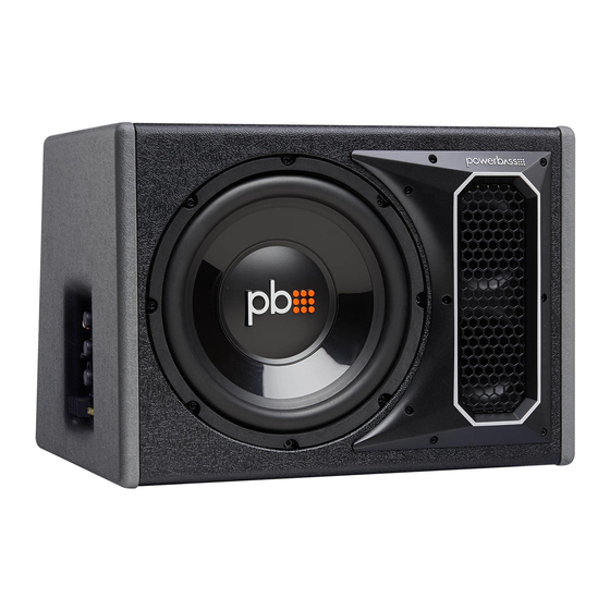
- Page 1 PS-AWB101 PS-AWB121 AMPLIFIED BASS REFLEX SYSTEM Application & Enclosure Guide Please read through this manual to familiarize yourself with your new subwoofer. Should your PowerBass Autosound Subwoofer System ever require service, you will need to have the original dated receipt.
- Page 2 At PowerBass USA, Inc. we are confident you will have many years of outstanding enjoyment from this great SPEAKER investment. For maximum performance we recommend that you have your new PowerBass Auto- sound product installed by an Authorized PowerBass Autosound Dealer.
- Page 3 POWERBASS AMPLIFIED BASS SYSTEM FEATURES Built-in High Powered Amplifier: Contains a high power Class A/B monaural amplifier complete with chassis mounted adjustable Gain, Low Pass Filter and Bass Eq controls for sonic integration into most existing factory or aftermarket car stereo systems and engineered perfectly to power the subwoofer.
- Page 4 Notify your local PowerBass dealer immediately should you notice any damage prior to installing the unit. Be sure to keep the carton and packing material until your system is operational. The original boxes will do the best job of protecting your speaker system if they need to be transported.
- Page 5 1) The amplifier heatsink end (opposite the woofer and port tube end) should be facing into a corner. See Fig 1. 2) Ideally there should be several inches clearance between the amplifier heatsink and the corner it is backed up to.
- Page 6 Mounting Bracket 14.4” (366mm) 11.4” 17” (432mm) (290mm) PS-AWB101 12.25” (311mm) Mounting Bracket 13.75” (349mm) NOTE: The speaker system must be secured to protect the enclosure from moving. Before final mounting, be sure to check the sound one last time and make sure the enclosure is properly placed to produce the desired bass output.
- Page 7 PS-AWB AMPLIFER CONTROL PANEL LAYOUT Fig.2 1. LOW INPUT (RCA) Jacks These RCA style input jacks are for use with source units that have RCA line level inputs. A source unit with a minimum output of 100mV is required for proper operation. However, this input can accept levels up to 6Vrms.
- Page 8 13. FUSE For convenience most PowerBass AutoSound amplifiers utilize common automotive ATC type fuses. For continued protection in the event that a fuse blows, replace the fuse only with the same value. PS-AWB101 uses a 15A fuse, PS-AWB121 uses a 20A CAUTION: These power fuses on the amplifier chassis are for protecting the amp against over current situation.
- Page 9 POWER WIRING AND SIGNAL CONNECTIONS POWER CONNECTION BATT+ The amplifier should be wired directly to the vehicle battery using a 8ga power cable. Start at the vehicle battery and run the power cable through the vehicle’s firewall using grommets to the amplifier’s BATT + screw terminal.
-
Page 10: Input Signal
INPUT SIGNAL (CHOOSING THE HIGH OR LOW INPUTS) The PS-AWB amplifer control panel input signal connects to the head unit’s High Level (speaker wire) output OR Low Level (RCA) output—provided the radio is so equipped with Line Out. A dedicated subwoofer or low level signal will deliver the best performance. - Page 11 Fig.4 High Level Connections LO W INPU T LP F 50H Z2 00H Z HIG H BA SS INPU T AU TO TURN O N OF F 0d B1 2d B REMO TE LEVEL PH AS E GAI N 0˚ 180˚...
- Page 12 Low Level Input and RCA Interconnect Wiring (fig 5) For radios that have RCA line outputs. You will need to connect the low-level RCA style inputs from the PS- AWB to the line-outputs from the radio (source) via an RCA interconnect commonly called a “stereo patch cord”.
- Page 13 Fig.5 Low Level Connections NOTE: Use 8ga power/ground wire for BATT+ and GND connections...
-
Page 14: Set-Up Adjustments
SET UP ADJUSTMENTS Your PS-AWB enclosure uses several controls to provide sonic integration with virtually any vehicles unique acoustic properties. Please read the following section carefully to familiarize yourself with the function of each control. The following adjustment sequence is recommended to properly tune your PS-AWB enclosure. By first adjusting the GAIN, the LPF, then the PHASE switch, followed by the BASS EQ (in this order) will give you the best results. - Page 15 NOTE: Although this adjustment sequence will in most cases provide the best tuning results, the actual process may include several readjustments of each of the controls since their settings interact with each other. If necessary, consult your Authorized PowerBass dealer for help tuning your system.
- Page 16 Fig.10 Connection with RJ45 Jack Remote Level Controller Your PowerBass PS-AWB enclosure includes a wired Remote Level Subwoofer control module. It uses standard telephone wire and telephone RJ45 connectors. To connect the Remote Subwoofer Gain control to the amplified enclosure, simply insert one end of the telephone plug into the REMOTE gain port. Plug the other end into the back of the remote module.
-
Page 17: Troubleshooting Tips
PHASE switch. This manual is the exclusive property of PowerBass USA, Inc. Any reproduction of this manual, or use other than its intentions is strictly prohib- ited without the express consent of PowerBass USA, Inc. -
Page 18: Warranty Notes
Should a warranty issue arise with our amplified subwoofer system PowerBass will replace the defective woofer only. Do not send the entire enclosure, unless the enclosure or amplifier is defective itself. PowerBass does not warranty the cosmetics of the enclosure once installed in the vehicle. - Page 19 Some states do not allow limitations on the length of an implied warranty, so this limitation may not apply. No person is authorized to assume for PowerBass any other liability in connection with the sale of this product.
- Page 20 PowerBass Autosound – A division of PowerBass USA, Inc. 2133 S. Green Privado – Ontario, CA 91761 Tel. (909) 923-3868 – Fax (909) 923-8048 www.powerbassusa.com...
Need help?
Do you have a question about the PS-AWB101 and is the answer not in the manual?
Questions and answers