Sign In
Upload
Download
Table of Contents
Contents
Add to my manuals
Delete from my manuals
Share
URL of this page:
HTML Link:
Bookmark this page
Add
Manual will be automatically added to "My Manuals"
Print this page
×
Bookmark added
×
Added to my manuals
Manuals
Brands
Jay-Lor Manuals
Mixer
5050
Owner's manual
Jay-Lor 5050 Owner's Manual
Hide thumbs
1
Table Of Contents
2
3
4
5
6
7
8
9
10
11
12
13
14
15
16
17
18
19
20
21
22
23
24
25
26
27
28
29
30
31
32
33
34
35
36
37
38
39
40
41
42
43
44
45
46
47
48
49
50
51
52
53
54
55
56
57
58
59
60
61
62
63
64
65
66
67
68
69
70
71
page
of
71
Go
/
71
Contents
Table of Contents
Troubleshooting
Bookmarks
Table of Contents
Table of Contents
1 Introduction
Figure 1 - Operator Orientation
2 Policy Statement
3 Owner/Operator's Responsibility
4 Contact Information
5 Serial Number Location
6 Customer Reference Information
7 Safety
Safety Alert Symbol
Understand Signal Words
Safety Guidelines
General Safety
Operating Safety
Driving and Hauling Safety
Maintenance and Repair Safety
Hydraulic Safety
Electrical Safety
Tire Safety
Storage Safety
Safety Signs
50 /5100 Safety Sign-Off Form
9 Safety Sign Locations
Safety Sign Locations (5050 Standard Models)
Figure 2 - 5050 Safety Decal Locations for Standard Models
Safety Sign Locations (5100 Standard Models)
Figure 3 - 5100 Safety Decal Locations for Standard Models
Figure 4 - Self-Propelled 'Warning' Decal
Figure 5 - General 'Warning' Decal
Figure 6 - 'Pinch Point Hazard' Decal
Figure 7 - 'Rotating Auger Hazard' Decal
Figure 8 - 'High Pressure Fluid Hazard' Decal
Safety Sign Locations (5050 CE Models)
Figure 9 - 5050 Safety Decal Locations for CE Models
Safety Sign Locations (5100 CE Models)
Figure 10 - 5100 Safety Decal Locations for CE Models
How to Install Safety Signs
Figure 11 - 'Rotating Auger and Rotating Knives' Decal
Figure 12 - 'Remove Ignition Key before Servicing' Decal
Figure 13 - 'Wear Ear Protection When Operating' Decal
Figure 14 - 'Wear Safety Boots When Operating' Decal
Figure 15 - 'Keep Safe Distance from Machine and Keep Children out of Range' Decal
Figure 16 - 'Read Manual before Operating, Maintaining, or Adjusting the Vertical Mixer' Decal
Figure 17 - 'Do NOT Drive on Steep Slopes' Decal
Figure 18 - 'Keep Safe Distance from Hot Surfaces' Decal
10 Machine Components
5050 Self-Propelled Mixer Components
Figure 19 - 5050 Self-Propelled Mixer Components
5050 Stationary Mixer Components
Figure 20 - 5050 Stationary Mixer Components
5050 Skid Steer Mixer Components
Figure 21 - 5050 Skid Steer Mixer Components
5050 Trailer Mixer Components
Figure 22 - 5050 Trailer Mixer Components
5050 Truck Mounted (CE Stationary) Mixer Components
Figure 23 - 5050 Truck Mounted (CE Stationary) Mixer Components
5100 Self-Propelled Mixer Components
Figure 24 - 5100 Self-Propelled Mixer Components
5100 Stationary Mixer Components
Figure 25 - 5100 Stationary Mixer Components
5100 Trailer Mixer Components
Figure 26 - 5100 Trailer Mixer Components
5100 Truck Mounted Mixer Components
Figure 27 - 5100 Truck Mounted Mixer Components
11 Operation
12 Pre-Operation Checklist
13 Breaking-In
Before Starting
After Operating for 1/2 Hour
After Operating for 5 Hours and 10 Hours
14 Controls
Weighing (All Models)
Figure 28 - Scale Mounting Bracket Arm Adjustment
Side Door Discharge (All Models)
Speed/Direction Control Pedal (Self-Propelled Models)
Figure 29 - Self-Propelled Speed/Direction Control Pedal
Auger On/Off Control (All Models)
Steering (Self-Propelled Models)
Throttle Control (Self-Propelled, Trailer, Truck Mounted Models)
Figure 30 - Self-Propelled Steering
15 Driving
16 Transporting
Transporting Trailer Models
Figure 31 - Trailer Coupler Positions
Figure 32 - Lug Tread Tire
Transporting Truck Mounted Models
Figure 33 - Truck Mounted Model Tie-Down Bracket Locations
Transporting the 5050 Skid Steer Model
Figure 34 - 5050 Skid Steer Model Transportation
17 Cutting and Mixing
18 General Field Operation
Figure 35 - Typical Total MIX Ration (TMR) Achieved in Mixing Chamber
19 Storage
20 Troubleshooting
21 Standard Model Specifications
22 Maintenance and Service Information
23 Maintenance Safety
24 Following an Effective Maintenance Schedule
25 Bolt Torque
Figure 36 - Imperial Bolt Markings
Figure 37 - Metric Bolt Markings
26 Fluids and Lubricants
Grease
Oil (Hydraulic System)
Oil (Engine)
27 Lubricating
Auger Support Bushings (All Models)
Figure 38 - Auger Support Bushing Grease Locations
Steering Chain and Sprocket Assembly (Self-Propelled Models)
Steering Shaft Support Bearings (Self-Propelled Models)
Figure 39 - Self-Propelled Steering Chain and Sprocket Lubrication
Figure 40 - Self-Propelled Steering Shaft Support Bearings Grease Locations
Steering Assembly (Self-Propelled Models)
Speed/Direction Control Bushing (Self-Propelled Models)
Figure 41 - Self-Propelled Steering Assembly Grease Locations
Figure 42 - Self-Propelled Speed/Direction Control Bushing Lubrication
Wheel Hubs (Trailer Models)
Caster Assembly (5050 Skid Steer Model)
Figure 43 - Trailer Hub Grease Location
Figure 44 - 5050 Skid Steer Model Caster Grease Location
28 Hydraulic System Maintenance
Checking Level in Hydraulic Oil Reservoir (5050 Models Except Skid Steer)
Figure 45 - 5050 Hydraulic System Oil Reservoir
Checking Level in Hydraulic Oil Reservoir (5100 Models)
Figure 46 - 5100 Hydraulic System Oil Reservoir
Replacing Hydraulic Oil and Hydraulic Oil Filter(S) (All Models Except Skid Steer)
Figure 47 - 5050 Self-Propelled Hydraulic Oil Filter Location
Figure 48 - 5050 Trailer, Stationary, Truck Mounted Hydraulic Oil Filter Location
Figure 49 - 5100 Self-Propelled, Trailer, Truck Mounted Hydraulic Oil Filter Locations
Maintaining the Breather
29 Engine or Electric Motor Maintenance
Figure 50 - 5100 Stationary Hydraulic Oil Filter Locations
30 Auger Maintenance
Knife Maintenance
Figure 51 - Auger Knife Setup
Auger Height Adjustment
31 Tire Air Pressure
Figure 52 - Auger Height Adjustment
32 Steering Chain Maintenance (Self-Propelled Models)
Figure 53 - Self-Propelled Steering Chain Adjustment
33 Trailer Coupler Maintenance (Trailer Models)
Figure 54 - Trailer Coupler Maintenance
34 Periodic Maintenance Chart
35 Maintenance and Service Records
36 EC Declaration of Conformity for Applicable Models
37 Safety Sign
38 Limited Warranty
Advertisement
Quick Links
Download this manual
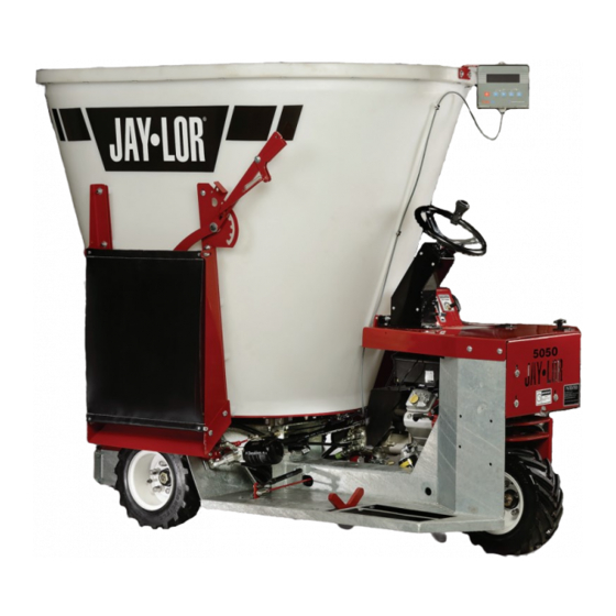
OWNER MANUAL
5050
5100
Table of
Contents
Previous
Page
Next
Page
1
2
3
4
5
Advertisement
Table of Contents
Need help?
Do you have a question about the 5050 and is the answer not in the manual?
Ask a question
Questions and answers
Related Manuals for Jay-Lor 5050
Mixer Jay-Lor 5425TM Owner's Manual
(71 pages)
Mixer Jay-Lor 5100 Owner's Manual
(71 pages)
Mixer Jay-Lor 4000 Series Operator's Manual
(44 pages)
This manual is also suitable for:
5100
Table of Contents
Print
Rename the bookmark
Delete bookmark?
Delete from my manuals?
Login
Sign In
OR
Sign in with Facebook
Sign in with Google
Upload manual
Upload from disk
Upload from URL


Need help?
Do you have a question about the 5050 and is the answer not in the manual?
Questions and answers