Table of Contents
Advertisement
Quick Links
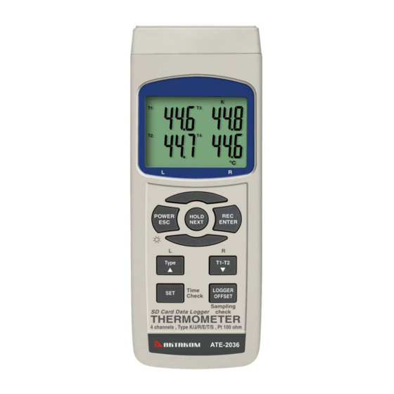
Type K/J /T/E/R/S, Pt 100 ohm
4 channels. T1, T2, T3, T4, T1-T2
SD card real time datalogger, RS232/USB
4 CHANNELS THERMOMETER
OPERATION MANUAL
Model : ATE-2036
www.tmatlantic.com
Your purchase of this 4
C H A N N E L S
THERMOMETER
S D
C A R D
DATALOGGER marks a
step forward for you
into
the
field
precision measurement.
Although this METER is
a complex and delicate
instrument, its durable
structure
will
many years of use if
p r o p e r
o p e r a t i n g
t e c h n i q u e s
developed. Please read
t h e
f o l l o w i n g
instructions
and always keep this
manual
within
reach.
with
of
allow
a r e
carefully
easy
Advertisement
Table of Contents

Related Manuals for Aktakom ATE-2036

Summary of Contents for Aktakom ATE-2036
- Page 1 Type K/J /T/E/R/S, Pt 100 ohm 4 channels. T1, T2, T3, T4, T1-T2 SD card real time datalogger, RS232/USB 4 CHANNELS THERMOMETER Model : ATE-2036 Your purchase of this 4 C H A N N E L S THERMOMETER with...
- Page 2 TABLE OF CONTENTS 1. FEATURES................1 2. SPECIFICATIONS..............2 3. FRONT PANEL DESCRIPTION..........6 3-1 Display................6 3-2 Power Button ( ESC, Backlight Button )......6 3-3 Hold Button ( Next Button )..........6 3-4 REC Button ( Enter Button )..........6 3-5 Type Button ( Button, L Button )........
- Page 3 1. FEATURES * Type K/J/T/E/R/S, Pt 100 ohm, measurement with 4 display. * Show 4 channels display on the LCD at the same time. * Type K : -100 to 1300 ℃ * Type J : -100 to 1200 ℃ * Pt 100 ohm : -199.9 to 850.0 ℃...
-
Page 4: Specifications
2. SPECIFICATIONS 2-1 General Specifications Circuit Custom one-chip of microprocessor LSI circuit. Display LCD size : 52 mm x 38 mm LCD with green backlight ( ON/OFF ). Channels T1, T2, T3, T4, T1-T2. Sensor type Type K thermocouple probe. Type J/T/E/R/S thermocouple probe. - Page 5 Temperature Automatic temp. compensation for the Compensation type K/J/T/E/R/S thermometer. Linear Linear Compensation for the full range. Compensation Offset Available for Type K/J/T/E/R/S and Adjustment Pt 100 ohm. Probe Input Type K/J/T/E/R/S Socket 2 pin thermocouple socket. Pt 100 ohm : Ear phone socket. Over Indication Show "...
-
Page 6: Electrical Specifications (23± 5 ℃ )
Power Current Normal operation ( w/o SD card save data and LCD Backlight is OFF) : Approx. DC 8.5 mA. When SD card save the data but and LCD Backlight is OFF) : Approx. DC 30 mA. * A If LCD backlight on, the power consumption will increase approx. - Page 7 Type K/J/T/E/R/S Sensor Resolution Range Accuracy Type Type K 0.1 ℃ -50.1 to -100.0 ℃ ± ( 0.4 % + 1 ℃ -50.0 to 999.9 ℃ ± ( 0.4 % + 0.5 ℃ 1 ℃ 1000 to 1300 ℃ ± ( 0.4 % + 1 ℃...
-
Page 8: Front Panel Description
3. FRONT PANEL DESCRIPTION Fig. 1 3-1 Display. 3-2 Power Button ( ESC, Backlight Button ) 3-3 Hold Button ( Next Button ) 3-4 REC Button ( Enter Button ) 3-5 Type Button ( Button, L Button ) ▲ 3-6 T1-T2 Button ( Button, R Button ) ▼... -
Page 9: Measuring Procedure
4. MEASURING PROCEDURE 4-1 Type K measurement 1) Power on the meter by pressing the " Power button " ( 3-2, Fig. 1 ) once. * After already power on the meter, pressing the " Power button " once ( > 2 sec ) will turn off the meter. - Page 10 4-3 Pt 100 ohm measurement 1) All the measuring procedures are same as the Type K ( section 4-1 ) except to select the Temp. Sensor type to " Pt " by pressing the " Type Button " ( 3-5, Fig. 1 ) once in sequence until the right down LCD display show "...
- Page 11 4-5 Data Hold During the measurement, press the " Hold Button " ( 3-3, Fig. 1 ) once will hold the measured value & the LCD will display a " HOLD " symbol. Press the " Hold Button " once again will release the data hold function.
-
Page 12: Data Logger
4-7 LCD Backlight ON/OFF After power ON, the " LCD Backlight " will light automatically. During the measurement, press the " Backlight Button " ( 3-2, Fig. 1 ) once will turn OFF the " LCD Backlight ". Press the " Backlight Button " once again will turn ON the "... - Page 13 5-2 Auto Datalogger ( Set sampling time 1 second ) ≧ a. Start the datalogger Press the " REC Button ( 3-4, Fig. 1 ) once , the LCD will show the text " REC ", then press the " Logger Button " ( 3-8, Fig.
- Page 14 5-3 Manual Datalogger ( Set sampling time = 0 second ) a. Set sampling time is to 0 second Press the " REC Button ( 3-4, Fig. 1 ) once , the LCD will show the text " REC ", then press the " Logger Button " ( 3-8, Fig.
- Page 15 5-5 Check sampling time information During the normal measurement ( not execute the Datalogger ), If press " Sampling Button " ( 3-8, Fig. 1 ) once , the lower LCD display will present the Sampling time information in second unit. 5-6 SD Card Data structure 1) When the first time, the SD card is used into the meter, the SD card will generate a folder :...
- Page 16 6. Saving data from the SD card to the computer ( EXCEL software ) 1) After execute the Data Logger function, take away the SD card out from the " SD card socket " ( 3-18, Fig. 1 ). 2) Plug in the SD card into the Computer's SD card slot ( if your computer build in this installation ) or insert the SD card into the "...
-
Page 17: Advanced Setting
EXCEL graphic screen ( for example ) 7. ADVANCED SETTING Under do not execute the Datalogger function, press the " SET Button " ( 3-7, Fig. 1 ) continuously at least two seconds will enter the " Advanced Setting " mode. then press the "... -
Page 18: Set Clock Time ( Year/Month/Date, Hour/Minute/ Second )
Remark : During execute the " Advanced Setting " function, if press " ESC Button " ( 3-2, Fig. 1 ) once will exit the " Advanced Setting " function, the LCD will return to normal screen. 7-1 Set clock time ( Year/Month/Date, Hour/Minute/ Second ) When the lower display show "... - Page 19 7-2 Decimal point of SD card setting The numerical data structure of SD card is default used the " . " as the decimal, for example "20.6" "1000.53" . But in certain countries ( Europe ...) is used the " , " as the decimal point, for example "...
- Page 20 7-4 Set beeper sound ON/OFF When the lower display show " bEEP " 1) Use the " Button " ( 3-5, Fig. 1 ) or " Button " ▲ ▼ ( 3-6, Fig. 1 ) to select the upper value to " yES " or "...
- Page 21 7-6 Set sampling time ( SecondS ) When the lower display show " SP-t " 1) Use the " Button " ( 3-5, Fig. 1 ) or " Button " ( ▲ ▼ 3-6, Fig. 1 ) to adjust the value ( 0, 1, 2, 5, 10, 30,60, 120, 300, 600, 1800,3600 seconds ).
-
Page 22: Power Supply From Dc Adapter
8. POWER SUPPLY from DC ADAPTER The meter also can supply the power supply from the DC 9V Power Adapter ( optional ). Insert the plug of Power Adapter into " DC 9V Power Adapter Input Socket " ( 3-13, Fig. 1 ). The meter will permanent power ON when use the DC ADAPTER power supply ( The power Button function is disable ). - Page 23 Meter (9W 'D" Connector) Center Pin......Pin 4 (3.5 mm jack plug) Ground/shield..... Pin 2 2.2 K resistor Pin 5 The 16 digits data stream will be displayed in the following format : D15 D14 D13 D12 D11 D10 D9 D8 D7 D6 D5 D4 D3 D2 D1 D0 Each digit indicates the following status : Start Word When send the upper display data = 1...
-
Page 24: Type K/J/T/E/R/S Offset Adjustment
RS232 FORMAT : 9600, N, 8, 1 Baud rate 9600 Parity No parity Data bit no. 8 Data bits Stop bit 1 Stop bit 11. OFFSET ADJUSTMENT 11-1 Type K/J/T/E/R/S offset adjustment 1) Set the function to Type K ( or other type J/E/R/T/S ). 2) Insert the probe to the T1 input socket ( 3-9, Fig. - Page 25 3) Pressing " Offset button " ( 3-8, Fig. 1 ) continuously at least two seconds then release, the display will show : Pt 1 Pt 2 4) If intend to make the offset adjustment for Pt 1, it should insert the probe to PT1 input socket.
-
Page 26: Optional Type K Temp. Probe
12. Optional Type K Temp. probe (Type K) TP-01 * Max. short-tern operating Temperature: 300 (572 ℃ ℉ * It is an ultra fast response naked-bead thermocouple suitable for many general purpose application. Thermocouple * Measure Range: -50 to 900 ℃...
Need help?
Do you have a question about the ATE-2036 and is the answer not in the manual?
Questions and answers