
Related Manuals for ROBOTIQ RWC-CAM-001


Summary of Contents for ROBOTIQ RWC-CAM-001
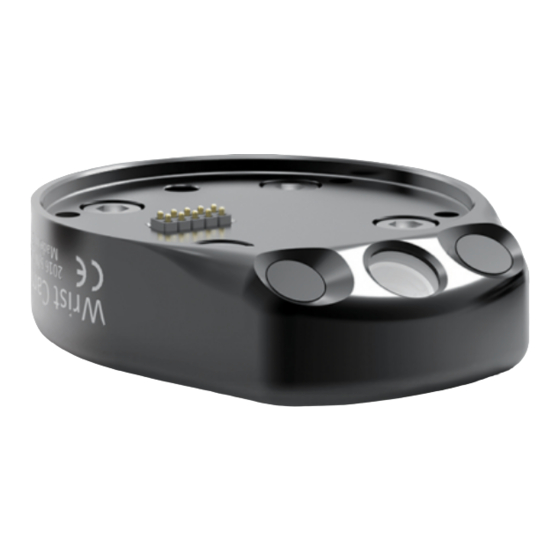
- Page 1 Original Notice © 2020 Robotiq Inc. Robotiq Wrist Camera for Universal Robots robot iq.com | leanrobot ics.org Instruction Manual...
-
Page 2: Table Of Contents
Revisions 1. General Presentation 1.1. Vision components 2. Safety 2.1. Warning 3. Installation 3.1. Scope of Delivery 3.2. Required Toolsand Equipment 3.3. Environmental and Operating Conditions 3.4. Mechanical Installation 3.5. Electrical Setup 4. Software 4.1. Installation, Uninstallation and Updates 4.2. Snapshot Position 4.3. - Page 3 10.1. Declaration of Incorporation 10.2. ngressProtection Certificate 11. Contact...
-
Page 4: Revisions
Modified appearance of text boxes. Added dynamic cross-references to sections of the Instruction Manual. Section " Required Tools and Equipment Modified electrical ratings shown in Table 1-1: Robotiq Wrist Camera and gripper power supply requirements Updated recommended optional equipment Subsection " Snapshot Position" :... - Page 5 Renamed section " Programming with the Camera Locate Node" to " Cam Locate Node" . Added sections: Save Image Node Scan Code Node Find Visual Offset and Apply Visual Offset Nodes, and Defining Tags Added subsections: In " Cam Locate Node" In "...
- Page 6 Updated technical specifications (Section 7.3). Updated calibration board for UR5 and UR10 robots (Section 4) 2016-11-16 Updated specifications (section 6) Updated installations instructions (section 4) Added Troubleshooting instructions (section 9.1) 2016-08-26 First release Wrist Camera - Instruction Manual...
- Page 7 This manual and the product it describes are protected by the Copyright Act of Canada, by laws of other countries, and by international treaties, and therefore may not be reproduced in whole or in part, whether for sale or not, without prior written consent from Robotiq.
-
Page 8: General Presentation
1 .1 . Vision components The figure below describes the various components of the Robotiq Vision system for Universal Robots. This system will use the Robotiq Wrist Camera, used with any of these mentioned Universal Robots versions (UR3, UR5, UR10, UR16). The system is compatible with the CB3.1 controller or later, as well as any e-Series releases. - Page 9 The object location process will always start at the snapshot position, that position will determine the field of view of the Wrist Camera i.e. the workspace. Consult the Snapshot Position section for more details. Fig. 1-2: Robotiq Vision System snapshot position and workplane concepts...
- Page 10 Info Snapshot Position Robot pose used to take snapshots with the Wrist Camera. Work Plane Areaof interest for the Vision System. Fits the field of view of the Wrist Camera. Object Object to locate using the Vision System. Calibration board Grid provided with the Wrist Camera.
- Page 11 Tool flange: ISO 9409-1:2004 4 X M6 ø 50mm bolt pattern Grippers are mounted on the Wrist Camera Info The Robotiq Wrist Camera provides a direct mounting interface for grippers, including a mechanical interface, 24V power and gripper/robot communication capabilities.
-
Page 12: Safety
Programming Decommissioning This manual covers the various components of the Robotiq Wrist Camera and the general operations regarding the whole life-cycle of the product, from installation to operation and decommissioning. The drawings and photos in this manual are representative examples. However, discrepancies may be observed between the visual supports and the actual product. -
Page 13: Warning
2.1 . Warning Caution Any use of the Wrist Camera in non-compliance with these warnings is deemed inappropriate and may cause injury or damage. Warning The Wrist Camera Vision System used in human-robot collaboration must not be considered a complete safety measure, additional dedicated safety device(s) must be considered. - Page 14 The unit may be used only within the range of its technical specifications. Any other use of the product is deemed improper and unintended use. Robotiq will not be liable for any damages resulting from any improper or unintended use.
-
Page 15: Installation
3. Installation The following subsections will guide you through the installation and general setup of your Robotiq Wrist Camera. Warning Before installing: Read and understand the safety instructions related to the Vision System. Verify your package according to the scope of delivery and your order. -
Page 16: Required Toolsand Equipment
3.1 .2. CUR-AGC-085-RWC or CUR-AGC-1 40-RWC Includes a 2-Finger Adaptive Gripperand a Wrist Camera. Wrist Camera Kit for Universal Robots includes: RobotiqWrist Camera with 10-m high flex cable 16 Gb USB stick USB software license dongle 4-port USB hub Calibration board Colored background for object teaching Hardware to mount the Wrist Camera to robots. - Page 17 The Wrist Camera needs to be supplied by a DC voltage source. This power supply is not included with the Wrist Camera Kit for Universal Robots. Required power supply must match the Robotiq device. The following table shows the specifications with regards to the power supply required to operate the Wrist Cameraand the optional Robotiq gripper.
-
Page 18: Environmental And Operating Conditions
3.4.1 . Mounting the Wrist Camera with an end-effector on Universal Robots 1. Place the Wrist Camera(RWC-CAM-001) on the robot arm. Align the wrist camera's dowel pin with tool flange. 2. Place the tool plate (RWC-TOOL-062) on the Wrist Camera. Align the tool plate dowel pin with theWrist Camera. - Page 19 Fig. 3-1: Mounting the Wrist Camera kit on Universal Robots Info The end-effector is secured directlyin the tool flange of the robot arm. Both the Wrist Camera and the tool plate are fitted with clearance holes for this assembly. M6 screws to mount an end-effector on the Wrist Camera are not provided. Use M6 screws of appropriate length to secure end-effector on robot arm.
- Page 20 3.4.2. Mounting the Wrist Camera with a Gripper on Universal Robots To mount a Wrist Cameraand a Robotiq Adaptive Gripper on a Universal Robots machine, follow these instructions, and refer to the figure below: 1. Place the Wrist Camera(RWC-CAM-001) on the robot arm. Align the Wrist Cameradowel pin with tool flange.
-
Page 21: Electrical Setup
3.5. Electrical Setup 3.5.1 . Pinout Interface The Wrist Camera interfaces with an end-effector (e.g. Robotiq Grippers) via a 10-spring pin connector located on its outer surface. 3.5.2. Power Supply Caution If mounting a 2-Finger Adaptive Gripper on the Wrist Camera, the latter acts as a gripper coupling. Therefore, only the Wrist Camera device cable is required to provide power and communication to both itself and the gripper. - Page 22 3. Connect the 4-port USB hub (ACC-USB-4-HUB) to the robot controller. 4. Connect the Wrist Camera USB cable to the 4-port USB hub. 5. Connect the USB license dongle (ACC-USB-DONGLE) to the 4-port USB hub. Fig. 3-4: Connecting to the 4-port USB hub Wrist Camera grounding is optional and is done via the robot ground.
-
Page 23: Software
Polyscope 3.9 and later versions. For details on updating your URCap, see Update and Uninstall section 1. Go to support.robotiq.com. 2. Click Select Product > Wrist Camera > Universal Robots > Software > Wrist Camera Software > DOWNLOAD ZIP. This down- loads the latest UCC-X.X.X compressed file. - Page 24 Fig. 4-2: Connecting to the 4-port USB hub. For CB-Series 1. Tap Setup Robot > URCaps Setup > , and select Robotiq_Wrist_Camera-X.X.X.urcap from the USB stick. 2. Tap , and wait for Polyscope to reboot. 3. Tap Program Robot > Installation > Camera > Dashboard tab. 4.
- Page 25 Fig. 4-4: The Camera tab indicates you must update the Wrist Camera firmware. 1. Wait for the Vision System to start. 2. The installation is completed. 3. In order to use another USB drive on the controller, reboot the robot controller. Warning Do not disconnect the 16 Gb USB stick or the USB license dongle from the robot controller, even after the installation has been completed.
- Page 26 4.1 .2. Update and Uninstall Warning Updating the Wrist Camera software, unplugging the USB storage device and/or switching USB ports must always be done while the robot is initialized and running. Version 1 .1and later For CB-Series: 1. From a robot program, go to the Installation tab > Camera > Dashboard > Stop camera > Uninstall. 2.
-
Page 27: Snapshot Position
Version 1 .1and earlier 1. Copy the following file : urmagic_uninstall.sh to a blank USB stick. 2. From a robot program, go to the Installation tab > Camera > Camera > Stop Camera. 3. With the controller on, insert the USB stick containing the urmagic file into the Teach Pendant. The uninstallation procedure starts automatically. - Page 28 1. Place the calibration board (ACC-CALIB-BOARD) on theWrist Camera work plane. Select the appropriate side for your Universal Robots model (see figures below). Fig. 4-6: Calibration board for UR5, UR10 and UR16 Universal Robots Fig. 4-7: Calibration board for UR3 Universal Robots models models. Info Color dots are not currently used by Robotiq software...
- Page 29 From the drop down list, choose either UR3 or UR5, UR10, UR16 > DOWNLOAD PDF. To print a calibration board, follow these recommendations. The official Robotiq two-sided calibration board is 357 mm x 278mm. Print as " Ledger/Tabloid" or " A3" formats. Use matte paper.
- Page 30 The button Hold to Align to Axis reorientates the Wrist Camera to make it parallel to an axis of the robot base. 3. The " Calibrating Camera" window is displayed, and the calibration process starts. Your robot moves around the calibration board, and the Vision System will take 27 pictures of the calibration board from different poses during 7-10 minutes.
-
Page 31: Saving The Snapshot Position
The wizard shows nine validation poses. Check the accuracy of validation poses: Dark blue: local accuracy of +/-0mm. Dark red: local accuracy of +/-4mm and over. If the accuracy is larger than +/- 4mm, you are told that you should recalibrate. Tap Accept to complete the calibration process. -
Page 32: Object Teaching
4.3.1 . Guidelines on Snapshot Position During the Snapshot position process, ambient light must be of approximately 500 lux. At run-time, this condition is not required. Snapshot position used for teaching objects may be different than the one used in production. However, camera angles and distances should be similar. - Page 33 Info One Cam Locate node is used per model taught . Object teaching is linked to a Snapshot position. Changing this position will require you to reteach the object. The background used when teaching objects should provide a high contrast. You can use the yellow/pink background provided with the Wrist Camera.
-
Page 34: Teach Object Wizard
The Machine edge view feature shows edges seen by the Vision System in grayscale format. See Teach Object Wizard section for more details. See section Vision System Specifications for specifications on color contrast. Runtime tips: Use a simple, uniform background. Your work plane should contain as few objects and object types as possible. - Page 35 Fig. 4-8: The CB-Series Teach object wizard. Fig. 4-9: e-Series Teach Object Cam Locate 4.5.2. Selecting the Teach Method Automatic method: builds a model based on photos and a scan of the object. Best for complex and irregular shapes. Use this method if the object orientation has to be detected with one of its features.
- Page 36 Fig. 4-10: Select the required method to teach an object. 4.5.3. Automatic Method Caution A Snapshot position must be defined to launch the object teaching wizard. If no Snapshot position has been defined, see Snapshot Position section Selecting a Calibration Tap the Calibration you want to use.
- Page 37 Fig. 4-11: " Select Calibration" step. Selecting a Model Prior to selecting a model, the user will place a background on the workplane and then position the object on the background. By default, the Select Model step displays the object to teach, automatically selected by the software, meaning a green selection rectangle overlaps the shape of the object.
- Page 38 Standard view button Machine edge view button Machine color view button Intensity view button; Automatic Area Selection The object is selected since the Magic Wand tool is enabled by default. The Magic Wand feature allows to locate objects on the background without user intervention.
- Page 39 Info Centering an object in the field of view often provides the best edges detection. Tapping toggles to Manual area selection mode. of the camera feed window to display all the views. Select the Machine view button to visualize edges detections and to optimize part location, depending on lighting setup.
- Page 40 Camera Viewing Modes The following viewing modes are available for the Wrist Camera: Standard view Machine Edge view Machine Color view Intensity view of the camera feed window to display all the views. Standard View When in standard view mode, the camera feed displays a reasonably faithful image based on what is normally perceived by the human eye (colored object on colored background).
- Page 41 Fig. 4-15: Select Model step with Machine edge view enabled The Machine edge view is a convenient tool that can be used to better understand the quality of the image and the object contrast, and to improve adjustments made to the selection. Machine Color View The Machine color view displays the elementary colors perceived by the vision system.
- Page 42 The Machine color view helps to understand the color signature and scale used by the system. Intensity view The intensity view displays the quality of illumination and uniformity of the vision system. Fig. 4-17: ''Select Model'' step with Intensity view enabled...
- Page 43 Camera Settings To access advanced settings, tap in the bottom left corner of the camera feed. Camera LEDs setting; see Software section for more details. Camera Exposure setting; see Software section for more details. Camera Focus setting; see Software section for more details. Camera White Balance setting;...
- Page 44 White Balance Automatic mode White Balance Manual mode Plus button increases a value. Minus button decreases a value. Reset button; the setting is reinitialized. Please refer to the specific setting sec- tion for more details...
- Page 45 Camera LED In addition to the Auto and Off settings, the Manual mode provides a Camera LED's intensity adjustment. The touch-sensitive slider can be used to select the right intensity more easily. Fig. 4-18: Select Model step with LED option enabled; (a) Auto, (b) Manual, and (c) OFF Wrist Camera - Instruction Manual...
- Page 46 When turned ON, LED sometimes highlight undesirable features or create reflections that can mask desired features of the image. It is recommended to try multiple settings, including the ON/OFF mode, when teaching the object in order to select the most conclusive result. Warning The flash and focus settings selected will be used at runtime unless changes are made at the Configure Model step at the end of the teaching process.
- Page 47 Fig. 4-20: Select Model step with Exposure option enabled (Automatic and Manual modes enabled) It is possible to reduce or eliminate camera image flicker (also seen as vertical moving bands) by matching camera exposure time with illumination frequency. See the following table to match exposure time and current frequency (50/60Hz). Wrist Camera - Instruction Manual...
- Page 48 Exposure time (ms) Category 50 Hz 60 Hz 10.0 8.333 Short Exposure 20.0 16.667 30.0 25.0 Medium Exposure 40.0 33.333 50.0 41.667 Long Exposure 60.0 50.0 58.333 Table 4-1: Suggested Exposure time versus Current Frequency (Hz). To improve image quality, it is recommended to increase exposure time before increasing gain. Info The exposure value (EV) represents a combination of exposure time and digital gain.
- Page 49 Automatic Focus Fig. 4-21: Select Model step with automatic focus option enabled. To some extent, the automatic focus feature detects sharpness in the overall image. If the image is blurry, the autofocus system will adjust the focus until sharpness and/or contrast is achieved. This type of automatic focus requires enough contrast between the object and the background for it to render an appropriate image.
- Page 50 The Focus adjustment slider is touch-sensitive. The position touched on the the slider area will determine the desired value. For finest possible adjustment, the +/- buttons can be used. White Balance White Balance is a parameter to get appropriate colors and better-defined shades of grey. It is always in Automatic but manual setting can be done by clicking on the Manual button.
- Page 51 When teaching metallic objects, using the pink mat will increase the contrast between the part and the background. Reduce the red channel and increase the green one to optimize the contrast of a shiny metallic object. Use the Machine View to adjust these parameters.
- Page 52 Zooming out Fig. 4-26: Select Model step with Zoom out button highlighted In order to zoom out from the selection area, the user has to tap the magnifier with a minus symbol in the lower right corner of the teach pendant interface.
- Page 53 Summary of Camera Settings Wrist Camera - Instruction Manual...
- Page 54 Editing the Model After accepting a model, the camera automatically zooms in on selected object . Tools are available. Outline only selection mode; please refer to the Software section for more details. Outline & surface selection model please refer to the Software section for more details.
- Page 55 Info For details on toggling color/machine view while editing a model, see Software section Quick Selection Modes Tap the arrow to the left of the quick selection tool to expand the selection modes menu. Fig. 4-28: Edit Model step with quick selection modes expanded. 1.
- Page 56 Tools Tap the arrow to the left of the tools button to expand the tools menu. Fig. 4-29: Edit Model step with tools menu expanded 1. Marker The marker tool can be used to highlight features and edges to include and keep in the selection area. Slide your finger or pointing device on the desired area(s) on the teach pendant.
- Page 57 Accepting the model 5. Check mark When the view of the model is satisfactory and you wish to carry on with the teaching wizard steps, tap the button with the check mark in the lower right corner of the teach pendant interface. Caution to take a picture of the model that will act as the first step in the next phase of the teaching process: "...
- Page 58 1. The user is prompted to turn the object 90 degrees clockwise. Note that 2. The user is prompted to take the second picture of the first picture is already taken, in the upper right corner. the object. 3. Object turned another 90 degrees clockwise. The user is prompted to 4.
- Page 59 Validating the Model The Validate Model step starts after the fourth picture is taken at the end of the Refine Model step. Info If the object is properly detected, it will display green and red outlines. If the object has not been recognized, please refer to the Software section for instructions. Accept button Retake...
- Page 60 Fig. 4-30: Scan Model step with Scan button highlighted The Vision System scans the object by taking 9 pictures. When the process is completed, the wizard will bring up the Configure Model step. Please refer to the Configure the model section for more information.
- Page 61 4.5.4. Parametric Method When teaching a simple geometry object, it is recommended to use the Parametric method. It builds a model based on parameters of a basic 2D shape (circle, ring, square or rectangle). This method allows the vision system to recognize and locate with high robustness objects that have few distinctive features such as raw material blanks.
- Page 62 Circle Enter the circle diameter (D) and the height (h) at which the circle is located. Tap the Define button. Fig. 4-32: Definition of a circle 2D shape. Ring Enter the ring outer diameter (D), inner diameter (d) and the height (h) at which the ring is located. Tap the Define button. Fig.
- Page 63 Rectangle Enter the rectangle length (l), width (w) and the height (h) at which the rectangle is located. Tap the Define button. Fig. 4-34: Definition of a rectangle 2D shape. Square Enter the square length (l) and the height (h) at which the square is located. Fig.
- Page 64 4.5.5. CAD model method 1. Import the CAD model file. Caution Make sure that the imported file is in the DXF-R12 format. 2. Click the Import button and select the DXF-R12 file. Fig. 4-36: CAD model imported...
- Page 65 3. Once the file is imported, make sure to adjust the height. The height mesure must be in mm. Fig. 4-37: CAD model imported with its added height When the process is done, the wizard will switch to the Configure Model step. Please refer to the Configure the model section below for more details.
- Page 66 4.5.6. Configure the model Test locating object button; the Vision System will search for the object in the field of view of the Wrist Camera. Back button; after testing an object's location, tap to return to the output image of the camera. Color validation button;...
- Page 67 Camera settings button; please refer to the Camera settings section for more details. Score value box; display section in which the detection score appears after testing the object location. Object location button; when an object is found, tap this button to view its position relative to the robot base.
- Page 68 Detecting Multiple Objects From the " Configure Model" window, tap Fig. 4-38: Configure Model with multi-object button highlighted. Once in the multi-object menu, tap the plus (+) symbol to increase the maximum number of objects to detect, or tap the minus (-) symbol to reduce that number.
- Page 69 Color Validation Color validation adds reliability to the Cam Locate functionality. Whereas editing the model allows to select, configure and save the shape, outline and area of the model, the color validation allows the system to save the color signature of objects or features. Warning Color validation is not intended for discriminating between two colors in the same Camera Locate node, no matter what the purpose is.
- Page 70 Fig. 4-41: Configure Model Color model with ON/OFF button highlighted Color sampling tools Fig. 4-42: Edit Color Validation with color sampling tools expanded 1. Marker The marker tool can be used to highlight features and edges to include and keep in the color sampling area. Slide your finger or pointing device on the desired area(s) on the teach pendant.
- Page 71 3. Rectangle+ (add area) The rectangle+ (add area) tool can be used to quickly highlight desired areas for color sampling. Tap and drag your finger or pointing device to draw rectangular shapes that will highlight available features. 4. Garbage can Tapping the garbage can icon will clear the object layer mask, thus deleting the selection area.
- Page 72 Fig. 4-43: Examples of Edges Score for (a) a blue part (b) a red part. Parametric method 1. Tap the color validation button to access the color validation menu. Fig. 4-44: Configure Model Step (Parametric method) with color validation button highlighted.
- Page 73 2. Turn on color validation by tapping the red button on the right side of the screen. Fig. 4-45: Edit Color Validation menu (Parametric method) with ON/OFF toggle button highlighted. Color sampling tool In the parametric method, given the inherent symmetry of the objects located by the system, color validation is supported via an expendable/shrinkable color selection zone, on part with the contour of the object to be located.
- Page 74 Detection thresholds and scores At the Configure model step, the user can tap the Detection threshold button in the lower right corner to expand the detection threshold settings. Fig. 4-47: Configure Model Step with detection thresholds highlighted. After adjusting the detection thresholds, if applicable, the user can test the location of the object(s) in the field of view by tapping the camera icon.
- Page 75 Info In the context of multiple objects detection, each object detected has its own set of detection score values (%). Edges detection threshold and score If the object is found, you will see the object outlined, surrounded by a blue rectangle, with the detection score value (%). If no object is found, an error message will display, reading that the object was not found.
- Page 76 Set the detection threshold at the highest value possible so the vision system detects the object on the whole workplane. Tap the Test locating object button to test the threshold. This ensures optimal robustness for object detection everywhere on the workplane. If it is not possible to reach such a success rate, the following should be considered: Redefine the Cam Locate node (go through the Teach object wizard again), make sure there are no reflections, or as few as possible.
- Page 77 Fig. 4-50: Multiple objects found each with their selection rectangles and detection scores. Wrist Camera - Instruction Manual...
- Page 78 Info In the context of multiple objects detection, each object detected has its own set of detection score values (%). Gripper Clearance Validation The Gripper Clearance Validation feature detects parts to avoid unwanted collisions between gripper and parts. Warning Gripper Clearance Validation applies to objects of the same modelbased on identical detection criteria. Other models or objects present in the picture will be disregarded.
- Page 79 1. Tap the Gripper Clearance Validation button Fig. 4-51: Configure Model with Gripper Clearance Validation button highlighted. 2. To toggle Clearance Validation, tap the red button on the right side of the screen. Fig. 4-52: Edit Collision Validation with ON/OFF button highlighted 3.
- Page 80 Gripper Clearance Sampling Tools Fig. 4-53: Edit Collision Validation with Gripper Cleanrance sampling tools expanded. 1. Marker The Marker tool highlights which features and edges to include in the object detection process. It can also be used to draw the clearance area for collision detection purposes.
- Page 81 3. Rectangle+ (add area) The Rectangle+ (add area) tool can be used to quickly highlight desired areas. This tool is extremely useful to define a rectangle for the gripper area. Tap and drag your finger or pointing device to draw rectangular shapes that will highlight available features. 4.
- Page 82 2. To toggle Clearance Validation, tap the red button on the right side of the screen. Fig. 4-55: Edit Collision Validation screen. Toggle button is highlighted. 3. Set the required clearance around the object using the plus and minus buttons.
- Page 83 Fig. 4-56: Setting up the clearance perimeter. 4. Tap the check mark button to confirm the model and collision areas shown on screen. Clearance verification While the program is running, it is possible to see if there is enough clearance around the parts seen by the wrist camera. Here are the steps to follow to get this information.
- Page 84 Fig. 4-57: Path to follow to have access to the clearance verification. On CB-Series robots: 1. Tap on the Installation tab at the top of the screen 2. Select Camera tab in the left pane of the screen 3. Select Camera menu . Fig.
- Page 85 The gripper clearance statuses are now available as shown in the figure below. Fig. 4-59: Gripper clearance status while program is running. Camera settings Warning Camera settings can be adjusted at the Select Model step of the Automatic teaching method and/or at the Configure Model step of the Teach object wizard.
-
Page 86: Cam Locate Node
Save location Once you are done with the test and adjustment, tap the Set reference position button. Caution Do not move the object after saving the position; the subsequent relative movements programmed will be relative to that position. Please refer to the Cam Locate node section for more details. Fig. - Page 87 The Cam Locate node acts as an " if" statement. If the taught object is detected by the camera, the robot program enters in the Cam Locate node and executes all command lines within it. After teaching the object within the Cam Locate node, you may continue the programming by using either a linear move (MoveL) with the Snapshot position variable as feature or the object_location pose.
- Page 88 By enabling the fast cycle time configuration, the camera exposure will be set the first time the program enters a Cam Locate node – at run time. For others Cam Locate nodes, the Vision System retains exposure settings used in the first run. Enabling this option halves cycle time.
- Page 89 Fig. 4-63: Cam Locate Loop, " Process one at a time" mode. Fig. 4-64: The Cam Locate loop can operate on two different modes. Process all When this option is selected, the Wrist Camera takes one pitcture, and finds objects (their number can be changed when teaching the object).
- Page 90 4.6.2. Linear Move with Feature Once the Teach Object wizard is completed, you saved the last position of your object. The object position variable, named after the snapshot position, now contains the reference frame of the object in this saved position. Each time the Camera Locate node localizes an object, it updates that feature variable's frame with the new detected object's position and orientation.
- Page 91 Fig. 4-66: Inserting a Move node with Universal Robots, e-Series models . 4.6.3. object_location pose Once a Snapshot position is defined, the work plane used for the calibration gets its own coordinate system, regardless of its orientation. This coordinate system is shown in the figure below. Fig.
- Page 92 Fig. 4-68: object_location pose on the workplane used for the calibration. object_location is a variable with the pose structure (x, y, z, x rotation, y rotation, z rotation): x: x position of the object detected, relative to the robot's base reference frame. y: y position of the object detected, relative to the robot's base reference frame.
- Page 93 y rotation: y rotation from the robot's base frame to the detected object feature reference frame. The object's Y axis is parallel to the workplane on which the calibration has been performed. z rotation: z rotation from the robot's base frame to the detected object feature reference frame. The object's Z axis is normal to the workplane on which the calibration has been performed, points downwards from it, into the workplane.
- Page 94 Fig. 4-71: Program example – Place the TCP 20 cm above the detected object, in case of an horizontal plane. CB-Series robot program is illustrated. Fig. 4-72: Program example – Place the TCP 20 cm above the detected object, in case of an horizontal plane. e-Series robot program is illustrated.
- Page 95 4.6.4. Edit Detection Threshold and Object Location It is possible to edit both the detection threshold and the object location after the Teach object wizard has been completed. Tap Cam Locate> Command > Test/Modify. Fig. 4-73: The taught object model can be viewed from the " Command" tab of a Cam Locate node. Objects can be retaught.
- Page 96 Object position can be modified. To do so, tap . The " Modify Model Position" window is displayed. Move object to its new position. To take the new picture, tap . To confirm this new position, tap . A warning mes- sage is displayed to prompt you to confirm this new position.To confirm, tap Define.
- Page 97 to exit the wizard. To modify only the detection threshold, modify it and test it. Wrist Camera - Instruction Manual...
- Page 98 Once it is at the required value, tap . This does not modify the object position previously saved. To modify both the threshold and the object location, adjust the threshold, place the object in the desired position and test is with the Test locating object button.
- Page 99 Fig. 4-74: Program example, using Universal Robots CB-Series models. Fig. 4-75: Program example, using Universal Robotse-Series models. Wrist Camera - Instruction Manual...
- Page 100 ignore_snapshot_position = True When using this method, make sure the workplane has the same orientation and distance regarding the position of the camera before a Cam Locate node. Using a variable and relative Snapshot position may decrease the precision, as the workplane can be slightly different depending on where the calibration has been performed.
- Page 101 Fig. 4-77: This MoveL node was inserted using the Auto Pick button. For a smoother experience using Auto Pick, modify teach pendant options under Installation > URCaps > Camera > Configurations. Check the following radio buttons: " Enable automatic pick points generation" "...
- Page 102 4.6.7. Camera Locate Settings You can configure a Cam Locate node using these options: Fig. 4-78: Cam Locate node settings. Option Description Ignore Snapshot Position The robot won't be required to be at the Snapshot Position for the Cam Locate during the pro- gram execution.
-
Page 103: Scan Code Node
4.7. Scan Code node 4.7.1 . Supported Types of Codes The Scan Code node is used to read various types of barcodes and 2D codes (QR, Datamatrix, PDF417). Code Image Type Aztec Datamatrix PDF-417 Code 93 EAN-8 EAN-13 ITF-14 UPC-E UPC-A Wrist Camera - Instruction Manual... - Page 104 Code 39 Code 128 4.7.2. Guidelines on Reading Codes Tips Follow these recommendations to improve codes readings. Code must be entirely visible in the field of view of the Wrist Camera. However, code should not fill the field of view entirely. Some whitespace must be left around its edges. Moving the Wrist Camera away from the code should increase its field of view and provide an adequate amount of whitespace.
-
Page 105: Using The Scan Code Node
4.8. Using the Scan code Node 1. Tap Program > URCaps > Scan Code. 2. Tap 3. The window " Select Code Type" is displayed. Tap the applicable code type. To navigate pages for additional code types, use 4. Put code on workplane, then tap , or retry by tapping if you are not satisfied with... - Page 106 5. To save your readings, tap . The " Scan Code Settings" window is displayed. 6. To save collected strings to a file, check either box, or both. If you choose to save your data loc- ally, you can use a USB stick to do so. The data will be stored in a .CSV file.
-
Page 107: Find And Apply Visual Offset Nodesand Defining Tags
The Wrist Camera Visual Offset capabilities are based on two nodes: Find Visual Offset and Apply Visual Offset. By attaching a Robotiq tag to a fixture (a tray, for instance), you can teach robot moves which are relative to this tag position. In other words, you can first teach the tag position, then teach moves, and even if your tray was moved, your robot program will compensate its move commands, first by finding out by how much the tray was displaced (using the node Find Visual Offset). - Page 108 6. Select the Camera Calibration to use to detect the tag. 7. Define Far Camera position: A far camera position have to be defined considering all the possible tag locations. The recommended Distance and Angle are: i. Far position: 200 to 350 mm ii.
- Page 109 To help you reach the recommended distance and angle, use the joystick and the button. You can also use the button to allow to center the tag in the middle of the picture while keeping the same orientation. To display the real time angle and distance , click on the button.
- Page 110 8. Define Close relative Camera position: Use the same method as previously described for the Far Camera position above. The recommended Distance and Angle are: i. Close position: 100 to 200 mm ii. Angle (Far or close): 50 to 70 ° and 110 to 130 °.
- Page 111 9. Once your tag is located and captured, click on Save & Finish to complete the Tag Creation. 4.9.2. Tag set and edition To edit or set the tag, go to Installation → URCaps → Camera → Tags. Caution Edit: allows you to change the camera position and settings. The Tag position will NOT be saved. Wrist Camera - Instruction Manual...
- Page 112 Caution Set: it resets the Tag position if you want to make some touch-ups. 1. Select the Tag to edit or to set and click on 2. You can either choose to Go to Snapshot Position or Define new Snapshot position. i.
- Page 113 Once you will have define the Far position and before setting the Close position, you will be asked if you want to 4.9.3. Using a Tag in a Robot program Once a tag has been defined, you can start creating your robot program . The tag can serve as a reference point for moves in your program.
- Page 114 4.9.4. Find Visual Offset node This node is used to calculate by how much a tag was moved, in reference to its value as calibrated previously. The value of the offset found by this Find Visual Offset node is temporarily saved, and you can reapply it in a Apply Visual Offset node. In the program, the condition "...
- Page 115 4. A tag is selected for the Find Visual Offset node. 4.9.5. Apply Visual Offset node The Apply Visual Offset takes the value by which a tag has been offset, and modifies robot moves that are under this Apply Visual Offset node in the program.
- Page 116 3. The " Select Tag For Visual Offset" window is displayed. Tap the tag you wish to use for your Apply Visual Offset node. 4. A Tag is selected for the Apply Visual Offset node. After inserting this node into your robot program , create the rest of your program under the Apply Visual Offset node. All robot moves will be adjusted based on the value injected by this node.
-
Page 117: Save Image Node
4.1 0. Save Image node You can take pictures with the Wrist Camera in the course of a robot program, and save them to a USB stick. This node is complementary to the Wrist Camera URCap nodes. Since saving an image can take up to five seconds for high-definition images, this node might slow down your cycle time. We recommend using the Save Image node under "... -
Page 118: Specifications
5. Specifications Info This manual uses the metric system. Unless otherwise specified, all dimensions are in millimeters. This section contains specifications for the RobotiqWrist Camera. Mechanical Specifications section Dimensions Maximum load Center of mass Moment of inertia Electrical and Optical Specifications section Electrical supply Resolution Vision System Specifications section... -
Page 119: Mechanical Specifications
5.1 . Mechanical Specifications Fig. 5-1: Dimensions of the Wrist Camera. Specifications Value Maximum load 10 kg / 40 Nm Weight (no tool plate) 160 g Weight (with tool plate) 230 g Added height (no tool plate, with a 2-Finger Adaptive Gripper) 13.5 mm Global thickness (no tool plate) 22.4 mm... - Page 120 1040 FT 300 and 2-Finger 85 1275 (CB-Series models) FT 300 and 2-Finger 140 1340 (CB-Series models) Table 5-2: Tool center point coordinates and payloads for some combinations of Robotiq harware with the Wrist Camera. Wrist Camera - Instruction Manual...
-
Page 121: Electrical And Optical Specifications
Inertia Matrix Metric value Imperial value (kg * mm (lb * in 0.38 0.24 0.01 0.01 0.56 Table 5-3: Moment of inertia matrix for the Wrist Camera. Values are approximated. Fig. 5-2: The Wrist Camera center of mass, without and with tool plate. 5.2. -
Page 122: Vision System Specifications
Specification Value Operating supply voltage 24 V DC ±20% Quiescent power (minimum power consumption) Maximum power 22 W Communication interface USB 2.0 Table 5-4: Wrist Camera electrical specifications. Specification Value Maximum resolution 5 Mpx at 2 fps (2560 X 1920) Maximum frame rate 30 fps at 0.3 Mpx (640 X 480) Active array size... - Page 123 Robot Model Accuracy +/- 2mm UR5/UR16 +/- 3mm UR10 +/- 3mm Fig. 5-3: Accuracy of the vision system. 5.3.2. Calibration Board Position Fig. 5-4: Calibration board position. Value Specifications UR10 UR16 Minimum board distance (cm) Maximum board distance (cm)
- Page 124 *Workplane surface to camera distance (considering the workplace surface at the same level as the robot base). **For indication only, larger field of view is possible depending on robot mounting configuration and parts locations. Contact Robotiq support if more information is required.
- Page 125 Fig. 5-5: Maximum and minimum part size. Caution The part must not be higher than its smallest dimension (width or length) : maximum of 1:1 ratio. Fig. 5-6: Maximum part height. Info Part height ratio is taken between the maximum part height at any point and the minimum dimension present on part contour, width or length.
- Page 126 5.3.5. Background contrast To ensure a good model and part detection from the Vision system, you should use a background that has a high color contrast with the part to be detected. You must choose colors that are apart horizontally on the HSV cone shown below. Therefore, a change in value (intensity) only does not represent a good contrast.
-
Page 127: Maintenance
6. Maintenance The Wrist Camera requires no maintenance. Make sure its lens remains free from liquid or dust. To clean the lens, apply alcohol and wipe it with the pouch that contained your Wrist Camera. The work plane should remain unchanged through time. Depending on your application, you should occasionally clean the work plane more or less regularly. -
Page 128: Spare Parts, Kitsand Accessories
Includes Wrist Camera, calibration board, tool plate for UR, USB memory stick, license and hub and all hardware. Replacement Wrist Camera. Includes 10 m pigtail cable. RWC-CAM-001 Wrist Camera tool plate for ISO 9409-1-50-4M6 pattern (Universal Robots). RWC-TOOL-062 Replacement calibration board. -
Page 129: Troubleshooting
8. Troubleshooting Info For details on the Vision server, Camera URCap and Wrist Camera firmware versions, go to the Installation tab > Camera > About. Versions are displayed. Check version numbers, and update all URCap to their latest release. LED colors can provide information on the issue you are facing. Read the table below for more details. LED status Description Solutions... -
Page 130: Warranty And Patent
Usage respects recommended payload and forces specified in the Mechanical Specifications of Wrist Camera section. During the warranty period, Robotiq will repair or replace any defective Wrist Camera, as well as verify and adjust the Camera free of charge if the equipment should need to be repaired or if the original adjustment is erroneous. If the equipment is sent back for verification during the warranty period and found to meet all published specifications, Robotiq will charge standard verification fees. - Page 131 Wrist Camera, the Vision System or other factors beyond Robotiq's control. Robotiq reserves the right to make changes in the design or construction of any of its products at any time without incurring any...
-
Page 132: Harmonized Standards, Declarations And Certificates
1 0. Harmonized Standards, Declarationsand Certificates 1 0.1 . Declaration of Incorporation Wrist Camera -Instruction Manual... - Page 133 1 0.2. ngress Protection Certificate...
- Page 134 1 1 . Contact www.robotiq.com Contact Us Phone 1-888-ROBOTIQ (762-6847) (01) 418-380-2788 Outside USand Canada Technical support and engineering option 3 Sales option 2 Head office Robotiq: 966, chemin Olivier Suite 500 St-Nicolas, Québec G7A 2N1 Canada Where automation Pros come to share their know-how and get answers.
Need help?
Do you have a question about the RWC-CAM-001 and is the answer not in the manual?
Questions and answers