Table of Contents
Advertisement
Quick Links
Advertisement
Table of Contents

Related Manuals for ROBOTIQ RWC-UR-KIT


Summary of Contents for ROBOTIQ RWC-UR-KIT
- Page 1 Get the latest version of the manual at support.robotiq.com © ROBOTIQ INC. 2016...
-
Page 2: Table Of Contents
A. Harmonized standards, declarations and certificates ..............50 Robotiq inc. © 2016... -
Page 3: Revisions
Revisions Robotiq may modify this product without notice, when necessary, due to product improvements, modifications or changes in specifications. If such modification is made, the manual will also be revised, see revision information. See the latest version of this manual online at: http://support.robotiq.com/... -
Page 4: General Presentation
1. General Presentation The terms "Camera" and "Wrist Camera" used in the following manual all refer to the Robotiq Wrist Camera, while the term "Vision" and "Vision System" used in the following manual all refer to the Robotiq Wrist Camera Vision System for Universal Robots . - Page 5 4 details on how to teach the Snapshot Position. Figure 1.2: Schematic representation of the Robotiq Vision System Snapshot Position and workspace concepts. Snapshot Position: the robot pose use to take snapshots from the Wrist Camera. Workspace: the area of interest for the Vision System, it is defined by the Camera's field of view.
- Page 6 Robotiq Wrist Camera Vision System for Universal Robots Instruction Manual Object Location : The System will use the Camera Locate node described in section 5 to locate the object. Figure 1.3 below represents the object location process. See secti on 5 for details on the object location process.
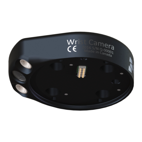
- Page 7 Robotiq Wrist Camera Vision System for Universal Robots Instruction Manual Wrist Camera : The hardware at the center of the Vision System is the Robotiq Wrist Camera illustrated in figure 1.4. Steps on how to install the Wrist Camera are explained in section 3 Figure 1.4: Wrist Camera main features.
-
Page 8: Safety
Instruction Manual 2. Safety Warning The operator must have read and understood all of the instructions in the following manual before handling the Robotiq Wrist Camera Vision System for Universal Robots The term "operator" refers to anyone responsible for any of the following operations on the Wrist Camera Vision System and associated robot or... -
Page 9: Warning
Robotiq Wrist Camera Vision System for Universal Robots Instruction Manual 2.1 Warning Note Any use of the Vision System in noncompliance of these warnings is inappropriate and may cause injury or damage. Warning Wrist Camera Vision System used in human-robot collaboration must not be considered a complete safety measure, additional dedicated safety device(s) must be considered. -
Page 10: Intended Use
Always comply with local and/or national laws, regulations and directives on automation safety and general machine safety. The unit may be used only within the range of its technical data. Any other use of the product is deemed improper and unintended use. Robotiq will not be liable for any damages resulting from any improper or unintended use. -
Page 11: Installation
Instruction Manual 3. Installation The following subsections will guide you through the installation and general setup of your Robotiq Wrist Camera Vision System. Section 3.1 details the scope of delivery for the Wrist Camera kit for UR, verify your package. -
Page 12: Scope Of Delivery
Robotiq Wrist Camera Vision System for Universal Robots Instruction Manual 3.1 Scope of Delivery Wrist Camera Kit for Universal Robots: RWC-UR-KIT Standard upon delivery: Robotiq Wrist Camera with 10m High-Flex pigtail cable RWC-CAM-001 Universal Robots pattern tool plate RWC-TOOL-062 16 Gig USB stick... -
Page 13: Required Tools And Equipment
The Camera needs to be supplied by a DC voltage source. This power supply is not included with the Camera kit for UR. Required power supply must match the Robotiq device. The following table shows the specifications with regards to the power supply required to operate the Camera and the optional Robotiq Gripper. -
Page 14: Environmental And Operating Conditions
Robotiq Wrist Camera Vision System for Universal Robots Instruction Manual 3.3 Environmental and Operating Conditions The Wrist Camera is designed for industrial applications. Always respect the following specified operating environmental conditions: Condition Value Minimum storage/transit temperature -30°C [-22°F] Maximum storage/transit temperature 70°C [158°F]... -
Page 15: Mechanical Installation
3.4 Mechanical Installation Wrist Camera kit for Universal Robots For mechanical installation of a Wrist Camera on a UR robot along with an end-effector (other than Robotiq's 2-Finger Gripper), follow these instructions and refer to Figure 3.4.1: Place the Wrist Camera (RWC-CAM-001) on the robot arm. Align the camera's indexing (dowel) pin properly in Universal Robots' bolt pattern. - Page 16 Combo of 2-Finger Adaptive Gripper and Wrist Camera for Universal Robots For mechanical installation of a Wrist Camera on a UR robot along with Robotiq's 2-Finger Gripper, follow these instructions, and refer to Figure 3.4.2: Place the Wrist Camera (RWC-CAM-001) on the robot arm. Align the camera's indexing (dowel) pin properly in Universal Robots' bolt pattern.
-
Page 17: Electrical Setup
Robotiq Wrist Camera Vision System for Universal Robots Instruction Manual 3.5 Electrical Setup Power Supply : 2-Finger Gripper If mounting a 2-Finger Gripper on the Wrist Camera, the Camera replaces the gripper's coupling. Therefore, only the Wrist Camera's device cable is required to provide power and communication to both the camera and the gripper. The wiring for setups including only the camera or both the camera and the gripper is the same. -
Page 18: Software Installation
Robotiq Wrist Camera Vision System for Universal Robots Instruction Manual 3.6 Software Installation The Wrist Camera's software installation has to be performed in two parts, in the order: Vision server installation - Section 3.6.1 URCap package installation - Section 3.6.2 Make sure the Wrist Camera is properly mounted to the robot arm and that all electrical wiring is correctly done. -
Page 19: Vision Server Installation
Robotiq Wrist Camera Vision System for Universal Robots Instruction Manual 3.6.1 Vision Server Installation Make sure the Wrist Camera is properly mounted to the robot arm and that all electrical wiring is correctly done. Refer to Section 3.4 detailed information on the mechanical and electrical installation. Before proceeding with the installation of the URCaps package, make sure your Universal Robots’... - Page 20 Robotiq Wrist Camera Vision System for Universal Robots Instruction Manual Figure 3.6.1.3: Connection on the 4 ports USB hub. Do not unplug the 16 Gig USB stick or the licence USB dongle, even after the installation is completed. A series of red popups will appear. The vision server is being installed. Wait for the popups to stop before going on to the next step.
-
Page 21: Urcaps Installation
Robotiq Wrist Camera Vision System for Universal Robots Instruction Manual 3.6.2 URCaps Installation Make sure the Wrist Camera is properly mounted to the robot arm and that all electrical wiring is correctly done. Refer to Section 3.4 detailed information on the mechanical and electrical installation. Before proceeding with the installation of the URCaps package, make sure your Universal Robots’... - Page 22 Gripper URCaps If using the Wrist Camera along with Robotiq's 2-Finger Gripper on the same robot, perform the URCaps installation procedure for the Wrist Camera before proceeding with the gripper's. See your 2-Finger Gripper instruction manual. Robotiq inc. © 2016...
-
Page 23: Uninstall And Update
Robotiq Wrist Camera Vision System for Universal Robots Instruction Manual 3.6.3 Uninstall and Update Follow these steps in order to properly uninstall the Wrist Camera's software - including the Vision server and the URCap package - before uninstalling completely or updating : Software update In order to update the Vision Server and URCap package, you need to uninstall both first before proceeding with the installation. -
Page 24: Snapshot Position
Calibration Boards: If you are viewing a printed version of this manual, please visit support.robotiq.com to download the file. For UR5 and UR10: Along with your kit you will have the calibration board used for UR5 and UR10 robots, part number... -
Page 25: Guidelines On Snapshot Position
Angle of the camera: Snapshot position should consider the Camera angle: Robotiq greatly recommends to have the Camera perpendicular to the surface: Be as close as possible to perpendicular, avoid reflections. Object should be seen from the top view, not from the side. -
Page 26: Snapshot Position Wizard
Robotiq Wrist Camera Vision System for Universal Robots Instruction Manual 4.2 Snapshot Position Wizard Feature Point: Prior to defining the Snapshot Position, the operator must define a feature point. To do so, from the Universal Robots Polyscope interface: Start a new program or open yours, then go to the Installation tab. - Page 27 Robotiq Wrist Camera Vision System for Universal Robots Instruction Manual Icon Feature Description Define Launches the Snapshot Position definition wizard. Show grid Displays a grid on the camera's field of view. Meant to test the camera’s height relative to the workplane : a part should be at least as large as a square of the grid.
-
Page 28: Object Teaching
Robotiq Wrist Camera Vision System for Universal Robots Instruction Manual 5. Object Teaching Once the Snapshot Position is defined (see section 4 ), the operator can use the Camera Locate node within a Universal Robot program to teach an object to locate. -
Page 29: Guidelines On Object Teaching
Robotiq Wrist Camera Vision System for Universal Robots Instruction Manual 5.1 Guidelines on Object Teaching The following must be considered when going through the object teaching process: Parts criteria for reliable localization: Object is quasi-flat, respecting a maximum ratio of 1:1 between it's height and it's smallest dimension (view Section 6.3... -
Page 30: Cam Locate Node & Teach Object Wizard
Robotiq Wrist Camera Vision System for Universal Robots Instruction Manual 5.2 Cam Locate Node & Teach Object Wizard Camera Locate node To insert a Camera Locate node in the robot program, from the Universal Robots Polyscope interface: Start a new program or open yours, then go to the Program tab. - Page 31 Robotiq Wrist Camera Vision System for Universal Robots Instruction Manual instance. Features Icon Feature Description Teach object Tap to launch the Object Teaching wizard. Choose Tap to select the Snapshot Position you want to use. Move Tap and hold to move the robot automatically to the Snapshot Position pose.
- Page 32 Robotiq Wrist Camera Vision System for Universal Robots Instruction Manual Robotiq inc. © 2016...
-
Page 33: Part Contours
Robotiq Wrist Camera Vision System for Universal Robots Instruction Manual 5.2.1 Part Contours With the Teach Object Wizard, the Vision System will outline features with a blue or red contour. During wizard step 2 and 3: Photos & Scan When taking the background photo, you should see your background contour outlined with a blue line an centered with a cross. This means the background was recognized properly. -
Page 34: Detection Score & Threshold Setting
Robotiq Wrist Camera Vision System for Universal Robots Instruction Manual 5.2.2 Detection score & threshold setting It is possible to modify the success rate at which the camera detects a part. This setting is defined in the Test and Save step of the object teaching wizard. -
Page 35: Programming With A Cam Locate Node
Robotiq Wrist Camera Vision System for Universal Robots Instruction Manual 5.3 Programming with a Cam Locate Node Info The URCaps install will provide you with a template program, template_vision.urp, that can be found in the program root folder. Figure 5.3.1 below shows this template. - Page 36 Robotiq Wrist Camera Vision System for Universal Robots Instruction Manual Figure 5.3.1: Template program for a Camera Locate pick & place application. Robotiq inc. © 2016...
-
Page 37: Specifications
The following manual uses the metric system, unless specified, all dimensions are in millimeters The following sub-sections provide data on the various specifications for the Robotiq 2-Finger 85 and 140 Adaptive Grippers. Section 6.1 mechanical specifications of the Wrist Camera: Dimensions;... -
Page 38: Mechanical Specifications Of Wrist Camera
Robotiq Wrist Camera Vision System for Universal Robots Instruction Manual 6.1 Mechanical Specifications of Wrist Camera Figure 6.1.1 : Wrist Camera's dimensions. Specification Value Maximum load 10 kg 40 Nm Weight (without tool plate) 160 g Weight (with tool plate) -
Page 39: Center Of Mass And Moment Of Inertia
UR tool flange reference [0,0,0]. Here is the approximate position for the center of mass. It has been calculated for the camera itself and for combinations with other Robotiq products. The camera's tool plate is included when the gripper is not mounted on the Wrist Camera. -
Page 40: Electrical Rating & Performance Of Wrist Camera
Robotiq Wrist Camera Vision System for Universal Robots Instruction Manual 6.2 Electrical rating & performance of Wrist Camera Robotiq recommends you supply the Wrist Camera from the Universal Robots controller power supply as shown in section 3.5 , if for any reasons you... -
Page 41: Vision System Specifications
Robotiq Wrist Camera Vision System for Universal Robots Instruction Manual 6.3 Vision System Specifications Calibration board position Figure 6.3.1 : Calibration board position. Specification Value UR10 Maximum board distance (cm) Minimum board distance (cm) Snapshot Position will determine the field of view, notice that the calibration step position does not have to be the same as Snapshot position. - Page 42 Robotiq Wrist Camera Vision System for Universal Robots Instruction Manual Part dimensions The maximum part size that can be detected by the Wrist Camera is 60% field of view's dimension. The minimum is 10%, no matter the robot or the field of view size.
- Page 43 Robotiq Wrist Camera Vision System for Universal Robots Instruction Manual Background contrast To ensure a good model and part detection from the Vision system, you should use a background that has a high color contrast with the part to be detected.
-
Page 44: Maintenance
Wrist Camera maintenance The Camera does not need any maintenance. Make sure that the lens is kept free from liquid or dust at all time. Robotiq recommends you use the provided bag with your camera along with alcohol to clean the lens. -
Page 45: Spare Parts, Kits And Accessories
Robotiq Wrist Camera Vision System for Universal Robots Instruction Manual 8. Spare Parts, Kits and Accessories Spare parts, kits and accessories list : The following list is up to date at print time and is subject to change, check online for updates. -
Page 46: Troubleshooting
Robotiq Wrist Camera Vision System for Universal Robots Instruction Manual 9. Troubleshooting Section 9.1 : LED status Versions To view the Vision server, Camera URCap and Camera firmware versions, proceed with the following : From a Robot program, go in the Installation tab. -
Page 47: Led Status
Robotiq Wrist Camera Vision System for Universal Robots Instruction Manual 9.1 LED status LED status Description Solutions The Camera is not powered. Check the Camera's power supply and electrical setup ( Section 3.5 Solid red No fault but the Camera is not Start or do a stop/start cycle of the Vision server. -
Page 48: Warranty & Patent
Wrist Camera, the Vision System or other factors beyond Robotiq's control. Robotiq reserves the right to make changes in the design or construction of any of its products at any time without incurring any obligation to make any changes whatsoever on units already purchased. -
Page 49: Contact
Robotiq Wrist Camera Vision System for Universal Robots Instruction Manual 11. Contact www.robotiq.com Contact us Phone 1-888-ROBOTIQ (762-6847) (01) 418-380-2788 Outside US and Canada 1-418-800-0046 Technical support and Engineering extension 207 Sales extension 122 Head office Robotiq 966, chemin Olivier Suite 325 St-Nicolas, Québec... -
Page 50: Harmonized Standards, Declarations And Certificates
Robotiq Wrist Camera Vision System for Universal Robots Instruction Manual A. Harmonized standards, declarations and certificates Note Details coming soon Robotiq inc. © 2016...
Need help?
Do you have a question about the RWC-UR-KIT and is the answer not in the manual?
Questions and answers