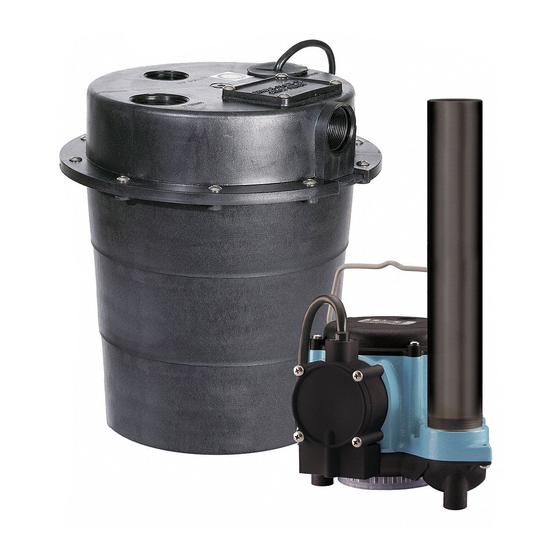
Little Giant WRS-6 Instruction Sheet
Wastewater removal system with 6-cia pump
Hide thumbs
Also See for WRS-6:
- Owner's manual (25 pages) ,
- Quick start manual (4 pages) ,
- Owner's manual (4 pages)
Advertisement
Quick Links
Franklin Electric Co., Inc.
P . O. Box 12010
Oklahoma City, OK 73157-2010
405.947.2511 • Fax: 405.947.8720
www.LittleGiantPump.com
CustomerService-WTS@fele.com
INTRODUCTION
EN
This instruction sheet provides you with the information required
to safely own and operate your product. Retain these instructions
for future reference.
The product you have purchased is of the highest quality work-
manship and material, and has been engineered to give you
long and reliable service. This product has been carefully tested,
inspected, and packaged to ensure safe delivery and operation.
Please examine your item(s) carefully to ensure that no damage
occurred during shipment. If damage has occurred, please con-
tact the place of purchase. They will assist you in replacement or
repair, if required.
READ
THESE
INSTRUCTIONS
ATTEMPTING
TO
INSTALL,
YOUR PRODUCT. KNOW THE PRODUCT'S APPLICATION,
LIMITATIONS,
AND
POTENTIAL
YOURSELF AND OTHERS BY OBSERVING ALL SAFETY
INFORMATION.
FAILURE
INSTRUCTIONS COULD RESULT IN PERSONAL INJURY
AND/OR PROPERTY DAMAGE!
DESCRIPTION
This unit is designed to pump wastewater from laundry trays,
washing machines, sinks, or dehumidifiers. It is not designed to
pump raw sewage, fluids other than water, or fluids with solids.
Inlet screen will remove many solids over 1/8" diameter, but large
amounts of solids can clog screen and result in pump failure.
Maximum fluid temperature is 125°F. Unit is designed to fit under
most sinks, so in many cases it is not necessary to recess the unit
into the floor.
ITEMS TO PURCHASE
NOTE: Some state or local codes require all electrical and/or
plumbing connections to be made by a licensed contractor. It is
the customer's responsibility to determine codes involved and
to comply with these codes. If user can install unit, items to
purchase are:
1. Inlet piping with trap and union. (Basin cover has 1-1/2" FNPT
fitting.)
2. Discharge piping with swing check valve and union. (Basin
cover has 1-1/2" FNPT fitting.)
3. Vent piping. (Basin cover has 2" FNPT fitting.)
SAFETY GUIDELINES
1. CAUTION: To reduce the risk of electric shock, pull plug
before servicing this pump.
2. Read all instructions and safety guidelines thoroughly. Failure
to follow the guidelines and the instructions could result in
serious bodily injury and/or property damage.
3. Check local electrical and building codes before installation.
The installation must be in accordance with these regulations.
4. During normal operation the pump is immersed in water. Use
caution to prevent bodily injury when working near the pump:
PumpAgents.com - Click here for Pricing/Ordering
WRS-6
Wastewater
Removal System
with 6-CIA Pump
CAREFULLY
BEFORE
OPERATE,
OR
SERVICE
HAZARDS.
PROTECT
TO
COMPLY
WITH
THESE
PumpAgents.com - Click here for Pricing/Ordering
a. Remove plug from the receptacle prior to touching, servic-
ing, or repairing the pump.
b. To minimize possible fatal electrical shock hazard, use
extreme care when changing fuses. Do not stand in water
while changing fuses or insert your finger into fuse socket.
ELECTRICAL CONNECTIONS
All wiring must meet local codes, and a licensed electrical
contractor is recommended. The pump is supplied with a 3-prong
vented plug. Plugs must be plugged into a grounded receptacle
and vent tube must remain unobstructed for proper pump
operation. Pump should be on a separate circuit with fuse or
circuit breaker and ground fault circuit interrupter (GFCI). Be sure
electrical supply matches pump nameplate data. Do not use
extension cord. If installed in basement, plug connection should
be 4' or more above floor, especially if basement floods. Be sure
electrical connections cannot be reached by rising water. Under
no circumstances should outlet box or receptacle be located
where it may become flooded or submerged by water.
INSTALLATION
All plumbing must meet local codes. A licensed plumbing con-
tractor is recommended. All fixtures connected to the WRS-6
Basin Kit must be vented according to state and local codes.
1. Determine proper location for unit. Locate unit so that inlet
is gravity-fed. Unit will not draw water up from a lower level.
Position and level basin. Keep basin away from any item that
could puncture basin. Position selected should be convenient
to inlet, discharge, and vent piping, and electrical supply.
2. Plumb inlet. Using 1-1/2" threaded pipe, plumb inlet to basin
cover fitting. Use a P-trap and a union next to the basin. Use
pipe joint compound and hand tighten only on plastic fittings.
Do not reduce below 1-1/2" piping.
3. Plumb discharge. Using 1-1/2" threaded pipe, plumb discharge
to basin cover fitting. Use a swing check valve no more than
3" from top of basin cover and a union. Be sure check valve is
installed in proper flow direction.
If check valve is installed backwards, no water will flow out
of unit. Be sure discharge piping is sealed with pipe joint
compound and that lift height of pump is not exceeded. Hand
tighten only on plastic fittings.
4. Plumb vent. Plumb vent using 2" threaded pipe to fitting in
basin cover. Use pipe joint compound on threads and hand
tighten only on plastic fittings. The basin must be vented in
accordance with state and local codes. The vent is essential for
proper switch operation and must not be omitted or restricted.
CAUTION: Do not use a mechanical vent with this product.
A mechanical vent will cause improper operation of the auto-
matic switch.
5. Test unit. Connect power cord to electrical supply as stated in
ELECTRICAL CONNECTIONS section. Secure power cord to
piping with ties or tape. Fill unit with water through inlet. Pump
should turn on with 7"–10" of water in tank, and turn off when
1"–3" of water is left in tank.
MAINTENANCE
WARNING: Before performing any maintenance, shut off water inlet
and disconnect power cord from supply outlet. Pump may become
hot during operation. Allow pump to cool before servicing.
Basin Screen: Remove 4 1/4-20 screen cover plate screws, plastic
cover plate, seal ring, and screen. Clean inlet screen using a mild
detergent and water. Examine O-ring and if deformed, replace
with new O-ring. See replacement parts table.
1
Advertisement

Related Manuals for Little Giant WRS-6


Summary of Contents for Little Giant WRS-6
- Page 1 All plumbing must meet local codes. A licensed plumbing con- ATTEMPTING INSTALL, OPERATE, SERVICE tractor is recommended. All fixtures connected to the WRS-6 YOUR PRODUCT. KNOW THE PRODUCT’S APPLICATION, Basin Kit must be vented according to state and local codes. LIMITATIONS, POTENTIAL HAZARDS.
- Page 2 PumpAgents.com - Click here for Pricing/Ordering Basin: Sediment may build up in basin causing pump to oper- Pump: Sediment or lint can clog pump and cause improper ate improperly. Remove 10 1/4-20 screws from cover. Remove operation. If necessary, remove pump and pull off the pressed- cord grommet and loosen cords to allow slack and then remove in screen.
- Page 3 MAX. PSI WRS-6 2750 1750 FOR TROUBLESHOOTING INFORMATION, SEE PUMP OWNERS MANUAL INCLUDED WITH WRS-6 BASIN KIT. ONE YEAR LIMITED WARRANTY For one year from date of purchase, Little Giant will repair this unit if defective in material or workmanship.
- Page 4 Para la ayuda técnica, por favor póngase en contacto ..1.888.956.0000 www.LittleGiantPump.com CustomerService-WTS@fele.com Form 993801 - 09/24/2009 © 2007 Franklin Electric Co., Inc. Little Giant® is a registered trademark of Franklin Electric Co., Inc. PumpAgents.com - Click here for Pricing/Ordering...