
Subscribe to Our Youtube Channel
Related Manuals for EMB Wallenstein CR60


Summary of Contents for EMB Wallenstein CR60
- Page 1 EMB MFG INC. COMMERCIAL TRAILER WOOD CHIPPER MODEL CR60 CR100 OPERATOR'S MANUAL...
- Page 2 • any device or accessories installed by parties other than an authorized EMB dealer or distributor Engines are covered by the manufacturer of the engine and covered by the warranty period specified by that manufacturer.
- Page 3 WALLENSTEIN COMMERCIAL TRAILER WOOD CHIPPER INSPECTION REPORT This form must be filled out by the dealer and signed by both the dealer and the customer at the time of deliv- ery. Customer’s Name Dealer Name Address Address City, State/Province, Code City, State/Province, Code Phone Number ( Phone Number (...
- Page 4 SERIAL NUMBER LOCATION Always give your dealer the serial number of your Wallenstein Commercial Trailer Wood Chipper when ordering parts or requesting service or other information. The serial number plates are located where indicated. Please mark the numbers in the spaces provided for easy reference.
-
Page 5: Table Of Contents
TABLE OF CONTENTS SECTION DESCRIPTION PAGE Introduction ............1 Safety ..............2 General Safety ............. 3 Equipment Safety Guidelines ......4 Safety Training ............. 5 Safety Signs ............5 Preparation ............6 Maintenance Safety ..........6 Operation Safety ..........7 Hydraulic Safety ........... -
Page 6: Introduction
INTRODUCTION Congratulations on your choice of an Wallenstein Commercial Trailer Wood Chipper to compliment your operation. This equipment has been designed and manufactured to meet the needs of a discerning tim- ber or landscaping industry. Safe, efficient and trouble free operation of your Wallenstein Wood Chipper requires that you and anyone else who will be using or maintaining the chipper, read and understand the Safety, Operation, Mainte- nance and Trouble Shooting information contained within the Operator's Manual. -
Page 7: Safety
SAFETY SAFETY ALERT SYMBOL This Safety Alert symbol means The Safety Alert symbol identifies ATTENTION! BECOME ALERT! important safety messages on the YOUR SAFETY IS INVOLVED! Wallenstein Commercial Trailer Wood Chipper and in the manual. When you see this symbol, be alert to the possibility of personal injury or death. -
Page 8: General Safety
GENERAL SAFETY SAFETY 1. Read and understand the Op- YOU are responsible for the SAFE operation and erator’s Manual and all safety maintenance of your Wallenstein Commercial signs before using, maintain- Trailer Wood Chipper. YOU must ensure that you ing, adjusting or cleaning the and anyone else who is going to use, maintain or Trailer Wood Chipper. -
Page 9: Equipment Safety Guidelines
EQUIPMENT SAFETY GUIDELINES 1. Safety of the operator and bystanders is one 7. Never exceed the limits of a piece of machin- of the main concerns in designing and de- ery. If its ability to do a job, or to do so safely, is in question - DON'T TRY IT. -
Page 10: Safety Training
SAFETY TRAINING SAFETY SIGNS 1. Keep safety signs clean and legible at all 1. Safety is a primary concern in the design and manufacture of our products. Unfortunately, times. our efforts to provide safe equipment can be wiped out by a single careless act of an 2. -
Page 11: Preparation
PREPARATION MAINTENANCE SAFETY 1. Never use the engine and machine until you 1. Good maintenance is your responsibility. Poor have read and completely understand this maintenance is an invitation to trouble. manual, the Engine Operator's Manual and each of the Safety Messages found on the 2. -
Page 12: Operation Safety
2.7 OPERATING SAFETY 11. Do not run machine inside a closed building to 1. Please remember it is important that you read prevent asphyxiation from engine exhaust. and heed the safety signs on the Commercial Trailer Wood Chipper. Clean or replace all 12. -
Page 13: Hydraulic Safety
2.8 HYDRAULIC SAFETY 2.10 TRANSPORT SAFETY 1. Make sure that all the components in the hy- 1. Comply with state and local laws governing draulic system are kept in good condition and safety and transporting of machinery on public are clean. roads. -
Page 14: Gas Motor Safety
2.11 GAS MOTOR SAFETY 14 DO NOT crank engine with spark plug removed. If engine is flooded, place throttle in "FAST" position and crank until engine starts. BEFORE STARTING ENGINE, READ AND UNDERSTAND THE OPERATING 15. DO NOT strike flywheel with a hard object or AND MAINTENANCE INSTRUCTIONS metal tool as this may cause flywheel to shat- THAT CAME WITH YOUR ENGINE. -
Page 15: Refueling Safety
2.12 REFUELING SAFETY 2.14 BATTERY SAFETY 1. Keep all sparks and flames away from batter- 1. Handle fuel with care. It is highly flammable. ies, as gas given off by electrolyte is explo- sive. 2. Allow engine to cool for 5 minutes before re- fueling. -
Page 16: Employee Sign-Off Form
2.15 SIGN-OFF FORM Wallenstein follows the general Safety Standards specified by the American Society of Agricultural and Biological Engineers (ASABE) and the Occupational Safety and Health Administration (OSHA). Anyone who will be using and/or maintaining the Commercial Trailer Wood Chipper must read and clearly understand ALL Safety, Usage and Maintenance information presented in this manual. -
Page 17: Safety Sign Locations
SAFETY SIGN LOCATIONS The types of safety signs and locations on the equipment are shown in the illustrations that follow. Good safety requires that you familiarize yourself with the various safety signs, the type of warning and the area, or particular function related to that area, that requires your SAFETY AWARENESS. •... - Page 18 The types of safety signs and locations on the equipment are shown in the illustrations that follow. Good safety requires that you familiarize yourself with the various safety signs, the type of warning and the area, or particular function related to that area, that requires your SAFETY AWARENESS. •...
- Page 19 The types of safety signs and locations on the equipment are shown in the illustrations that follow. Good safety requires that you familiarize yourself with the various safety signs, the type of warning and the area, or particular function related to that area, that requires your SAFETY AWARENESS. REMEMBER - If safety signs have been damaged, removed, become illegible or parts replaced without safety signs, new signs must be applied.
- Page 20 The types of safety signs and locations on the equipment are shown in the illustrations that follow. Good safety requires that you familiarize yourself with the various safety signs, the type of warning and the area, or particular function related to that area, that requires your SAFETY AWARENESS. Z94008 REMEMBER - If safety signs have been damaged, removed, become illegible or parts replaced without safety signs, new signs must be applied.
-
Page 21: Operation
OPERATION OPERATING SAFETY • Please remember it is important that you read • Never use alcoholic beverages or drugs which the operator's manual and heed the safety can hinder alertness or coordination while signs on the Commercial Trailer Wood Chipper. operating this equipment. -
Page 22: Machine Components
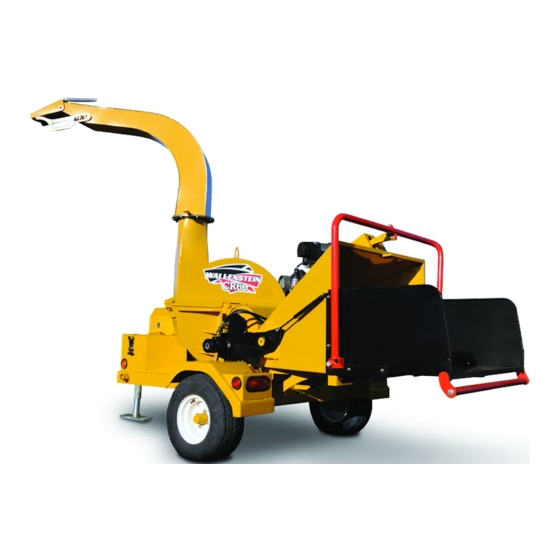
MACHINE COMPONENTS a rotor with blades for chipping wood. A feed hopper Power is transmitted through a centrifugal clutch on The Wallenstein Commercial Trailer Wood Chipper is moves the wood material into the rotor. Hydraulically the engine output shaft and through a V belt drive driven rollers in the throat of the feed hopper pull and system. -
Page 23: Machine Break-In
MACHINE BREAK-IN PRE-OPERATION CHECKLIST Although there are no operational restrictions on the Efficient and safe operation of the Wallenstein Com- Commercial Trailer Wood Chipper when used for mercial Trailer Wood Chipper requires that each the first time, it is recommended that the following operator reads and understands the using proce- mechanical items be checked: dures and all related safety precautions outlined in... -
Page 24: Controls
CONTROLS Before starting to work, all operators should famil- iarize themselves with the location and function of controls. Gas Engine: Read the engine manufacturers operator's man- ual before starting for more detailed instructions. a. Ignition Switch: This key operated switch controls the electric power to the engine. - Page 25 Hydraulic Feed Control Lever: This lever is positioned to extend around the feed hopper and provides access from all sides. Pull the control all the way out to engage the feeding system. Push in slightly to the first detent to stop the feeding system. Push the control all the way in to reverse the feeding system.
- Page 26 3. Deflector Position: Each discharge hood is equipped with a de- flector on the end to place the chips exactly where desired. The deflector support bracket is designed with slots to position the deflector where desired. Place in the appropriate slot. Close Fig.
- Page 27 Panic Bar: The feed hopper entrance is designed with a feed table that is equipped with a "Panic Bar" which is designed to stop the feed rollers should an operator be pulled into the feed hopper. Push the latch toward the roller to reset the "Panic Bar".
-
Page 28: Control Unit Operation And Programming
CONTROL UNIT OPERATION & PROGRAMMING Review this section prior to operating the machine. Normal Operation and Readouts: a. Digital Readout: Changes based on selected mode. b. Oil Use Hours: Default display can be reset to zero. c. Rotor RPM: Displays when rotor is turning d. - Page 29 Programming Upper Flow Percentage: 1. Press mode button three times. Digital readout will display current upper flow setting. This represents the percent of hydraulic flow that will be sent to the feed rolls (Feed speed.). 2. Oil Use indicator will flash. Increase or decrease setting using program buttons Fig.
- Page 30 Programming Lower Flow Percentage: 1. Press mode button five times. Digital rea- dout will display current lower flow setting. This represents the percent of hydraulic flow that will be sent to the feed rolls (Feed speed.). 2. Machine indicator will flash. Increase or decrease setting using program buttons (Kohler 38 HP gas: 35%.
-
Page 31: Attaching/Unhooking
ATTACHING/UNHOOKING The Commercial Trailer Wood Chipper should always be located on a level, dry area that is free of debris and other foreign objects. When attaching the machine to a power unit, follow this procedure: 1. Make sure that all bystanders, especially small children, are clear of the working area. - Page 32 8. Connect the wiring harness for the lights. 9. Route the harness and cables across the hitch to prevent snagging. Be sure to pro- vide slack for turning. Fig. 16 STAND/WIRING HARNESS 10. Pull out the lock pin and pull up to place jack frame in its storage place.
-
Page 33: Field Operation
FIELD OPERATION OPERATING SAFETY • Please remember it is important that you read • Never use alcoholic beverages or drugs which the operator's manual and heed the safety can hinder alertness or coordination while signs on the Commercial Trailer Wood Chipper. operating this equipment. - Page 34 5. Starting the Machine: a. Turn machine off, stop and disable engine, remove ignition key and place in your pocket, set park brake and wait for all moving parts to stop be- fore servicing, adjusting, repairing or unplugging. b. Close the choke if the engine is cold. c.
- Page 35 8. Feeding: a. Slowly slide the wooden material into the feed hopper and move it into the roller. b. Pull on the feed lever to engage the feed rollers to move the material into the rotor. c. Do not push the material - use the feed rollers.
- Page 36 9. Blades: There are 2 types of blades used on the Wood Chipper. They work together to cut, shear and shred the wood as it moves through the machine. a. Rotor blades: The rotor is equipped with 2 blades placed at 180° to each other to keep the rotor in balance.
- Page 37 10. Twig Breaker: Each machine is equipped with a twig breaker to break up twigs or other long material as it moves through the rotor compartment. Open the rotor cover and check the condition of the breaker on a weekly basis. Also check for any entangled material when the rotor cover is opened.
- Page 38 11. Belt Drive System: A V belt drive system transmits power from the engine to the rotor. A centrifugal clutch on the engine output shaft engages when the RPM reaches 1400 RPM. Always set the throttle to the 1/4 position when starting to prevent the clutch engaging and the rotor turning when starting.
- Page 39 12. Unplugging: Although the machine is designed to han- dle a wide variety of material without any problem, occasionally it plugs. When the machine plugs, follow this procedure to unplug: a. Clear the area of bystanders, especially small children. b. Reverse the feed rollers to remove the material from the feed hopper.
- Page 40 13. Refuelling: The fuel tank is located in the front frame and is accessed by lifting the cover over the cap. Use the fuel gauge on top of the tank when checking the level of fuel in the tank. Do not overfill.
- Page 41 16. Sharpening Blades: The rotor and stationary blades need to be sharp for the chipper to perform as ex- pected. It is recommended that the rotor blades be removed from the rotor when sharpening. Always sharpen the blades at a 45° angle to provide the best cutting effect as it meets the stationary blade.
- Page 42 17. Hydraulic System: The chipper is designed with a self-con- tained hydraulic system with a tank, pump, valves, motors and appropriate hoses. Pressurized oil is used to power the feed rollers. It also allows the feed roller drive system to be part of the material feeding system.
- Page 43 18. Electrical System: The chipper is designed with an electri- cal system that includes a CPU (Central Processing Unit), display, speed sensor and electro-hydraulic valve. The CPU measures the rotor speed through the speed sensor and closes the valve when the rotor speed slows.
- Page 44 19. Panic Bar: The feed table is designed with a "Panic Bar" on the end of the feed hopper intake. It is designed to stop the feed rollers should an operator be pulled into the hop- per. The feed table is designed with a latch in the center of the frame.
- Page 45 20. Personal Protective Equipment (PPE): Each person must wear appropriate personal protective equipment whenever operating the chipper or working in the vicinity. This equip- ment is designed to prevent injury to any personnel in the area. This list includes but is not limited to: •...
-
Page 46: Transporting
TRANSPORTING TRANSPORT SAFETY • Do not exceed a safe travel speed. • Always use a mechanical retainer through the ball hitch mechanism when attaching to • Always follow and obey applicable highway tow vehicle. rules and regulations. • Do not drink and drive. •... -
Page 47: Storage
4.10 STORAGE 13. Do not allow children to play around the stored OPERATING SAFETY unit. When removing this machine from storage, follow • Store the unit in an area away from human activity. 4.9.2 REMOVING FROM STORAGE • Do not permit children to play on or around this procedure: the stored machine. -
Page 48: Service And Maintenance
SERVICE AND MAINTENANCE 5.1 SERVICE MAINTENANCE SAFETY 5.1.1 FLUIDS AND LUBRICANTS • Good maintenance is your responsibility. 1. Grease: Poor maintenance is an invitation to trouble. Use an SAE multipurpose high temperature grease with extreme pressure (EP) performance. • Follow good shop practices. Also acceptable is an SAE multipurpose lithium base grease. - Page 49 5.1.2 SERVICING INTERVALS The period recommended is based on normal operating conditions. Severe or unusual con- ditions may require more frequent lubrication or oil changes. 8 Hours or Daily 1. Check engine oil level. Fig. 36 DIP STICK 2. Check fuel level. Fig.
- Page 50 40 Hours or Weekly 1. Check rotor drive belt tension. Move the engine to set the belt tension. Fig. 39 ROTOR DRIVE SYSTEM 2. Clean engine air cleaner. Fig. 40 AIR CLEANER 3. Check sharpness of blades: Rotor. Stationary. Remove, sharpen or change edge as required.
- Page 51 100 Hours or Monthly 1. Change engine oil. Fig. 42 DRAIN PLUG 2. Check tire pressure. Fig. 43 TIRES (Typical) 3. Change engine oil filter. Fig. 44 OIL FILTER...
- Page 52 100 Hours 4. Grease rotor bearings. IMPORTANT Do not over grease. Front Rear Fig. 45 BEARINGS 5. Replace engine air cleaner. Fig. 46 AIR CLEANER...
- Page 53 6. Grease feed roller bearings. 7. Grease the feed roller pivot. Left Side Right Side Fig. 47 FEED ROLLER...
- Page 54 Annually 1. Replace in-line fuel filter. Fig. 48 FUEL FILTER 2. Replace hydraulic filter. Fig. 49 HYDRAULIC FILTER 3. Clean machine. Fig. 50 MACHINE...
- Page 55 5.1.3 SERVICE RECORD See Lubrication and Maintenance sections for details of service. Copy this page to continue record. ACTION CODE CHECK CLEAN REPLACE GREASE CHANGE HOURS SERVICED MAINTENANCE 8 Hours or Daily CK Engine Oil Level CK Fuel Level CK Hydraulic Oil Level 40 Hours or Weekly CK Rotor Drive Belt Tension CL Air Cleaner...
-
Page 56: Maintenance
MAINTENANCE By following a careful service and maintenance program for your machine, you will enjoy many years or trouble-free operation. 5.2.1 CLEANING AIR CLEANER 1. Review the Operator's Manual for the en- gine. 2. Place all controls in neutral, stop engine and remove ignition key and wait for all moving parts to stop before maintaining. - Page 57 5.2.2 CHANGING ENGINE OIL AND FILTER Review the Operator's Manual for the en- gine. Place all controls in neutral, stop engine and remove ignition key and place in pock- et before maintaining. Allow the engine to cool before changing the oil. Hot oil can cause burns if it con- tacts exposed skin.
- Page 58 5.2.3 DRIVE BELT TENSION AND ALIGNMENT A V belt transmits rotational power to the ro- tor. It must be kept properly tensioned and the pulleys aligned to obtain the expected perform- ance and life. To check the tension and alignment, follow this procedure: Clear the area of bystanders, especially small children.
- Page 59 Lay a straight edge across the pulley faces to check the align- ment. Adjust alignment if pulley faces vary more than 1/32 inch (.8 MM). Fig. 54 PULLEY ALIGNMENT...
-
Page 60: Troubleshooting
TROUBLE SHOOTING The Wallenstein Commercial Trailer Wood Chipper is designed with blades on a rotor to cut, shear and shred wooden material. It is a simple and reliable system that requires minimal maintenance. In the following section, we have listed many of the problems, causes and solutions to the problems that you may encounter. - Page 61 PROBLEM CAUSE SOLUTION Feed rollers do not turn. Low hydraulic oil. Add oil to reservoir. Plugged hydraulic filter. Replace filter. Controller isn't working. Check electrical system. Charge battery. Replace controller. Sensor not working. Check sensor and set to 2 mm (3/16 inch) clearance. Replace sensor Rotor stalls.
-
Page 62: Specifications
SPECIFICATIONS MECHANICAL CR60 Drive system Belt drive. centrifugal clutch. Engine 38 hp Kohler Chipper Capacity 6" Diameter (takes up to 10" slab). Chipper Housing 6 1/2" by 12" Opening Rotor Size 30" Number of Rotor Knives Knife Type Hardened tool steel Rotor Weight 180 lbs. -
Page 63: Bolt Torque
BOLT TORQUE CHECKING BOLT TORQUE The tables shown below give correct torque values for various bolts and capscrews. Tighten all bolts to the torques specified in chart unless otherwise noted. Check tightness of bolts periodically, using bolt torque chart as a guide. Replace hardware with the same strength bolt. ENGLISH TORQUE SPECIFICATIONS Bolt Torque* Bolt... -
Page 64: Hydraulic Fitting Torque
HYDRAULIC FITTING TORQUE Tube Nut Size Torque Recommened Tightening Flare Type Tube Fittings * Size Across Value• Turns To Tighten Flats (After Finger 1. Check flare and flare seat for defects Tightening) that might cause leakage. (in.) (in.) (N.m) (lb-ft) (Flats) (Turn) 2. -
Page 65: Index
INDEX PAGE PAGE Safety ..............2 Index ..............60 Battery Safety ...........10 Introduction ............1 Equipment Safety Guidelines .....4 Gas Motor Safety........9 General Safety ...........3 Maintenance Safety ........6 Operating Safety.........7 Preparation ..........6 Operation ............16 Safety Signs ..........5 Attaching/Unhooking.........26 Safety Training..........5 Controls ............19 Sign-Off Form ........... 11 Control Unit Operation &...
Need help?
Do you have a question about the Wallenstein CR60 and is the answer not in the manual?
Questions and answers